Table Of Contents
Catalyst 6500 Series DFC, DFC3A, DFC3B, and DFC3BXL Installation Note
Hardware and Software Requirements
DFC Hardware and Software Requirements
DFC3A, DFC3B, DFC3BXL Hardware and Software Requirements
Cisco Product Security Overview
Reporting Security Problems in Cisco Products
Obtaining Technical Assistance
Cisco Technical Support Website
Definitions of Service Request Severity
Obtaining Additional Publications and Information
Catalyst 6500 Series DFC, DFC3A, DFC3B, and DFC3BXL Installation Note
Product numbers:
WS-F6K-DFC(=)
WS-F6K-DFC3A(=)
WS-F6K-DFC3B(=)
WS-F6K-DFC3BXL(=)
Note
Throughout this publication, unless otherwise noted, the term DFC refers to the DFC, DFC3A, DFC3B, and DFC3BXL.
This publication describes how to install the Catalyst 6500 series Distributed Forwarding Card (DFC) on Catalyst 6500 series fabric-enabled modules.
Note
You can only install the DFC on fabric-enabled modules. See the "Hardware and Software Requirements" section for more information.
Contents
This publication contains these sections:
•
Hardware and Software Requirements
•
Cisco Product Security Overview
•
Obtaining Technical Assistance
•
Obtaining Additional Publications and Information
Hardware and Software Requirements
The requirements for using the DFC or DFC3A are as follows:
•
DFC Hardware and Software Requirements
•
DFC3A, DFC3B, DFC3BXL Hardware and Software Requirements
DFC Hardware and Software Requirements
To install and use the DFC, you need the following:
•
Catalyst 6500 series switch (Catalyst 6506, 6509, 6509-NEB, or 6513) or Cisco 7600 series router (Cisco 7606, 7609, or 7613)
•
Supervisor Engine 2 with Multilayer Switch Feature Card 2 (MSFC2) running Cisco IOS software on the Supervisor Engine 2 and MSFC2
Note
You cannot have a DFC in a system with a Supervisor Engine 720.
•
Fabric-enabled module
•
Switch Fabric Module (SFM) (WS-C6500-SFM) or SFM 2 (WS-X6500-SFM2)
Note
The SFM must be installed in slot 5 or slot 6 of the 6-slot or the 9-slot chassis. The SFM cannot be installed in the 3-slot or 13-slot chassis.
Note
The SFM 2 must be installed in slot 5 or slot 6 of the 6-slot or the 9-slot chassis or in slot 7 or slot 8 of the 13-slot chassis.
DFC3A, DFC3B, DFC3BXL Hardware and Software Requirements
To install and use the DFC3A, DFC3B, or DFC3BXL, you need the following:
•
Catalyst 6500 series switch (Catalyst 6503, 6506, 6509, 6509-NEB, or 6513) or Cisco 7600 series router (Cisco 7603, 7606, 7609, or 7613)
•
Supervisor Engine 720 with MSFC3 running Cisco IOS software on the Supervisor Engine 720 and MSFC3
Note
You cannot have a DFC3A, DFC3B, or DFC3BXL in a system with a Supervisor Engine 2.
•
Fabric-enabled module
Note
Supervisor Engine 720 supports a DFC3A, DFC3B, or DFC3BXL on these WS-X6516-GBIC hardware revisions:
•
Lower than 5.0
•
5.4 and higher
Supervisor Engine 720 does not support a DFC3A, DFC3B, or DFC3BXL on WS-X6516-GBIC hardware revisions 5.0 through 5.3. With a Supervisor Engine 720 and with a DFC3A, DFC3B, or DFC3BXL installed, WS-X6516-GBIC hardware revisions 5.0 through 5.3 do not power up.
Without a DFC3A, DFC3B, or DFC3BXL, WS-X6516-GBIC hardware revisions 5.0 through 5.3 operate in bus mode.
Safety Overview
Safety warnings appear throughout this publication in procedures that, if performed incorrectly, may harm you. A warning symbol precedes each warning statement.
Warning
Only trained and qualified personnel should be allowed to install, replace, or service this equipment.
Parts List
These parts are in the DFC kit:
•
One Catalyst 6500 series DFC, DFC3A, DFC3B, or DFC3BXL
•
One disposable grounding wrist strap
•
One bag of mounting screws
Required Tools
These tools are required to install the Catalyst 6500 series DFC:
•
Antistatic mat or foam pad to support the removed module
•
Number 1 Phillips screwdriver for the screws and cap nuts that fasten the DFC to the module
•
Your own ESD-prevention equipment or the disposable grounding wrist strap included with all upgrade kits, field-replaceable units (FRUs), and spares
Whenever you handle a module, always use a wrist strap or other grounding device to prevent electrostatic discharge (ESD).
Installation Guidelines
Follow these guidelines when installing a DFC:
•
When installing the DFC in a system with a Supervisor Engine 720, observe the following restrictions for DFC3/PFC3 mismatch:
•
Observe the following cautions:
CautionDuring this procedure, wear grounding wrist straps to avoid ESD damage to the module. Do not directly touch the backplane with your hand or any metal tool, or you could shock yourself.
CautionUse care not to damage the connectors on the module. If you damage a connector, it will be necessary to return the module to Cisco for repair.
CautionYou must install screws in all available standoffs. The screws provide grounding between the DFC3 and the module. Failure to install all screws will invalidate the safety approvals and pose a risk of fire and electrical hazard.
Removing the DFC
Note
Throughout this publication, unless otherwise noted, the term DFC refers to the DFC, DFC3A, DFC3B, and DFC3BXL.
Note
The figures in this procedure show the DFC. The procedure is the same for the DFC, DFC3A, DFC3B, and DFC3BXL.
CautionDuring this procedure, wear grounding wrist straps to avoid ESD damage to the module. Do not directly touch the backplane with your hand or any metal tool, or you could shock yourself.
To remove the DFC, perform these steps:
Step 1
Remove the module from the Catalyst 6500 series switch. (Refer to the Catalyst 6500 Series Switch Module Installation and Verification Note for removal instructions.)
Step 2
Place the module on an antistatic mat or foam, with the front of the module facing toward you.
Step 3
Use a Phillips-head screwdriver to remove the securing screws and the two cap nuts from the DFC. (See Figure 1.)
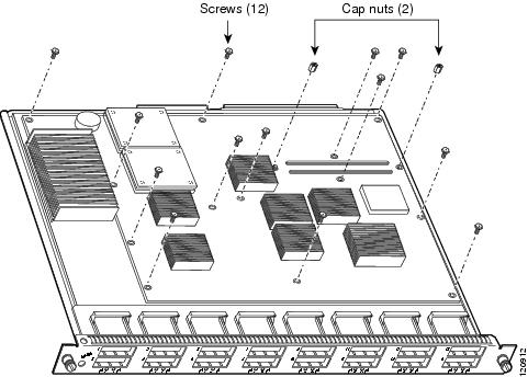
Figure 1 DFC Securing Screws and Cap Nuts
Step 4
Grasp the module at the two locations shown in Figure 2 and gently move the DFC up and down to loosen the board connectors.
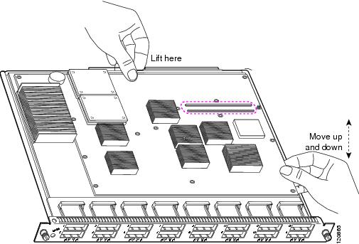
Figure 2 Disconnecting the DFC from the Module
Step 5
Disconnect the power connector as shown in Figure 3.
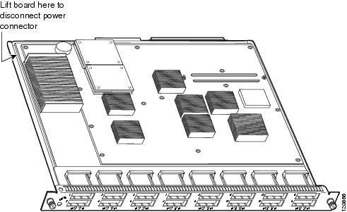
Figure 3 Disconnecting the Power Connector
Step 6
Gently lift the DFC with both hands simultaneously, and remove the DFC from the module as shown in Figure 4.
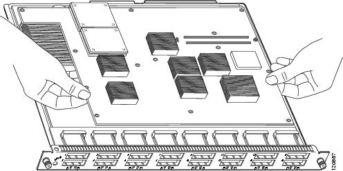
Figure 4 Removing the DFC
Step 7
Place the removed DFC on an antistatic mat or antistatic foam pad.
Installing the DFC
Note
Throughout this publication, unless otherwise noted, the term DFC refers to the DFC, DFC3A, DFC3B, and DFC3BXL.
Note
The figures in this procedure show the DFC. The procedure is the same for the DFC, DFC3A, DFC3B, and DFC3BXL.
CautionDuring this procedure, wear grounding wrist straps to avoid ESD damage to the card. Do not directly touch the backplane with your hand or any metal tool, or you could shock yourself.
To install the DFC on a fabric-enabled module, follow these steps:
Step 1
Remove the module from the Catalyst 6500 series switch. (Refer to the Catalyst 6500 Series Module Installation Guide for removal instructions.)
Step 2
Place the module on an antistatic mat or foam, with the front of the module facing toward you (see Figure 6).
Step 3
Remove the DFC from its antistatic bag.
Step 4
Align the two mounting holes on the DFC (see Figure 5) with the two male standoffs on the module (see Figure 6). Make sure that the remaining mounting holes on the DFC are aligned with the remaining standoffs.
Note
The DFC is designed to be installed on different modules; therefore, there may be more mounting holes on the DFC than there are standoffs on the module. Not all mounting holes on the DFC will be used in all installations. Visually verify that there are standoffs beneath the mounting holes before installing the securing screws.
Figure 5 Mounting Holes on the DFC
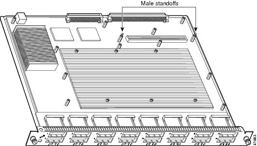
Figure 6 Male Standoff Locations on the Module
Step 5
Ensure that the connectors on the DFC are aligned with the connectors on the module. Figure 7 shows the connectors on the underside of the DFC.
Figure 7 Distributed Forwarding Card Connectors
Step 6
Apply pressure to the area shown in Figure 8 to seat the power connector.
Figure 8 Seating the Power Connector
CautionThe following step shows how to preseat the DFC on the module. Preseating the DFC allows you to verify that the keys on the connectors are properly aligned. Fully seating the DFC when the connectors are not aligned will damage the connectors on both the DFC and the module. If you damage a connector, you will have to return the module to Cisco for repair. It is important that the DFC is preseated prior to being fully seated.
Step 7
With your left hand, apply firm pressure at the location shown in Figure 9. While applying pressure with your left hand, move the DFC up and down with your right hand, no more than half an inch in either direction, to preseat the DFC on the module.
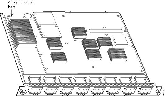
Figure 9 Preseating the Connector
Step 8
Verify that the keys on the connector are aligned and that the gap between the key and the opposing connector is no more than 1/16 inch (1.6 mm) before fully seating the module (see Figure 10):
•
If the keys are not aligned, remove the DFC and repeat Step 4 through Step 7.
•
If the keys are not seated far enough, repeat Step 7.
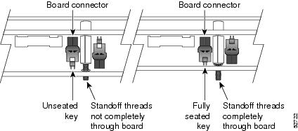
Figure 10 Connector Keys
Step 9
With the bottom of your hand, apply firm pressure to the location shown in Figure 11 to fully seat the DFC on the module.
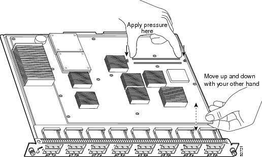
Figure 11 Seating the Distributed Forwarding Card on the Module
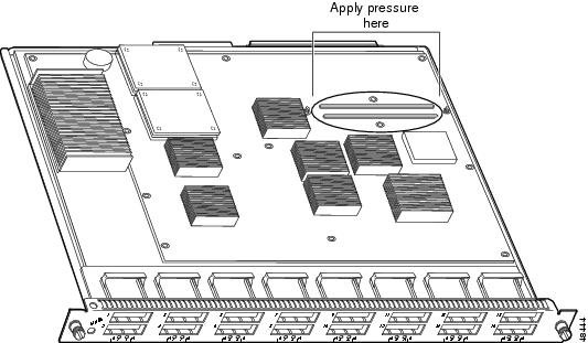
Note
The DFC is fully seated when there is no gap between the connector keys, and the bottom of the DFC is in contact with the tops of the standoffs (see Figure 10).
CautionUsing the screws to seat the DFC could warp the card. Before you install and tighten the securing screws, ensure that the DFC is fully seated by visually verifying that there is no gap between the male and female keys on the connectors and that the bottom of the DFC is in contact with the tops of the standoffs (see Figure 10).
Step 10
Use a Phillips-head screwdriver to install the two screws at the front of the DFC and the one screw at the power connector in the order shown in Figure 12.
Note
You should visually verify that there are standoffs beneath the mounting holes before installing the securing screws.
Figure 12 Installing the First Set of Screws
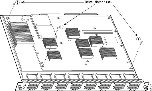
Step 11
Use a Phillips-head screwdriver to install the two cap nuts and two screws that surround the connector (see Figure 13).
Figure 13 Installing the Second Set of Screws and Cap Nuts
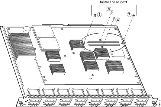
Step 12
Use a Phillips-head screwdriver to install the remaining screws (see Figure 14).
CautionYou must install screws in all available standoffs. The screws provide grounding between the DFC and the module. Failure to install all screws will invalidate the safety approvals and pose a risk of fire and electrical hazard.
Note
You should visually verify that there are standoffs beneath the mounting holes before installing the securing screws.
Figure 14 Installing the Remaining Screws
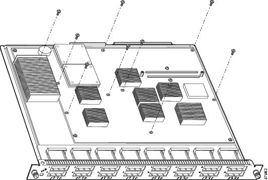
Step 13
Install the module in the Catalyst 6500 series switch.
Refer to the Catalyst 6500 Series Module Installation Guide for installation instructions.
Step 14
Power up the switch.
If the switch comes online, the system acknowledges the module and the DFC. The switch brings the module and DFC online.
Related Documentation
These documents are available for the Catalyst 6500 series switches:
•
Regulatory Compliance and Safety Information for the Catalyst 6500 Series Switches
•
Catalyst 6500 Series Switch Module Installation and Verification Note
•
Catalyst 6500 Series Switch Installation Guide
•
Catalyst 6500 Series Switch Module Guide
•
Catalyst 6500 Series Switch Software Configuration Guide
•
Catalyst 6500 Series Switch Command Reference
•
Catalyst 6500 Series Switch Cisco IOS Software Configuration Guide
•
Catalyst 6500 Series Switch Cisco IOS Command Reference
•
Catalyst 6500 Series DFC Memory Upgrade Installation Note
Obtaining Documentation
Cisco documentation and additional literature are available on Cisco.com. Cisco also provides several ways to obtain technical assistance and other technical resources. These sections explain how to obtain technical information from Cisco Systems.
Cisco.com
You can access the most current Cisco documentation at this URL:
http://www.cisco.com/univercd/home/home.htm
You can access the Cisco website at this URL:
You can access international Cisco websites at this URL:
http://www.cisco.com/public/countries_languages.shtml
Documentation DVD
Cisco documentation and additional literature are available in a Documentation DVD package, which may have shipped with your product. The Documentation DVD is updated regularly and may be more current than printed documentation. The Documentation DVD package is available as a single unit.
Registered Cisco.com users (Cisco direct customers) can order a Cisco Documentation DVD (product number DOC-DOCDVD=) from the Ordering tool or Cisco Marketplace.
Cisco Ordering tool:
http://www.cisco.com/en/US/partner/ordering/
Cisco Marketplace:
http://www.cisco.com/go/marketplace/
Ordering Documentation
You can find instructions for ordering documentation at this URL:
http://www.cisco.com/univercd/cc/td/doc/es_inpck/pdi.htm
You can order Cisco documentation in these ways:
•
Registered Cisco.com users (Cisco direct customers) can order Cisco product documentation from the Ordering tool:
http://www.cisco.com/en/US/partner/ordering/
•
Nonregistered Cisco.com users can order documentation through a local account representative by calling Cisco Systems Corporate Headquarters (California, USA) at 408 526-7208 or, elsewhere in North America, by calling 1 800 553-NETS (6387).
Documentation Feedback
You can send comments about technical documentation to bug-doc@cisco.com.
You can submit comments by using the response card (if present) behind the front cover of your document or by writing to the following address:
Cisco Systems
Attn: Customer Document Ordering
170 West Tasman Drive
San Jose, CA 95134-9883We appreciate your comments.
Cisco Product Security Overview
Cisco provides a free online Security Vulnerability Policy portal at this URL:
http://www.cisco.com/en/US/products/products_security_vulnerability_policy.html
From this site, you can perform these tasks:
•
Report security vulnerabilities in Cisco products.
•
Obtain assistance with security incidents that involve Cisco products.
•
Register to receive security information from Cisco.
A current list of security advisories and notices for Cisco products is available at this URL:
If you prefer to see advisories and notices as they are updated in real time, you can access a Product Security Incident Response Team Really Simple Syndication (PSIRT RSS) feed from this URL:
http://www.cisco.com/en/US/products/products_psirt_rss_feed.html
Reporting Security Problems in Cisco Products
Cisco is committed to delivering secure products. We test our products internally before we release them, and we strive to correct all vulnerabilities quickly. If you think that you might have identified a vulnerability in a Cisco product, contact PSIRT:
•
Emergencies — security-alert@cisco.com
•
Nonemergencies — psirt@cisco.com
Tip
We encourage you to use Pretty Good Privacy (PGP) or a compatible product to encrypt any sensitive information that you send to Cisco. PSIRT can work from encrypted information that is compatible with PGP versions 2.x through 8.x.
Never use a revoked or an expired encryption key. The correct public key to use in your correspondence with PSIRT is the one that has the most recent creation date in this public key server list:
http://pgp.mit.edu:11371/pks/lookup?search=psirt%40cisco.com&op=index&exact=on
In an emergency, you can also reach PSIRT by telephone:
•
1 877 228-7302
•
1 408 525-6532
Obtaining Technical Assistance
For all customers, partners, resellers, and distributors who hold valid Cisco service contracts, Cisco Technical Support provides 24-hour-a-day, award-winning technical assistance. The Cisco Technical Support Website on Cisco.com features extensive online support resources. In addition, Cisco Technical Assistance Center (TAC) engineers provide telephone support. If you do not hold a valid Cisco service contract, contact your reseller.
Cisco Technical Support Website
The Cisco Technical Support Website provides online documents and tools for troubleshooting and resolving technical issues with Cisco products and technologies. The website is available 24 hours a day, 365 days a year, at this URL:
http://www.cisco.com/techsupport
Access to all tools on the Cisco Technical Support Website requires a Cisco.com user ID and password. If you have a valid service contract but do not have a user ID or password, you can register at this URL:
http://tools.cisco.com/RPF/register/register.do
Note
Use the Cisco Product Identification (CPI) tool to locate your product serial number before submitting a web or phone request for service. You can access the CPI tool from the Cisco Technical Support Website by clicking the Tools & Resources link under Documentation & Tools. Choose Cisco Product Identification Tool from the Alphabetical Index drop-down list, or click the Cisco Product Identification Tool link under Alerts & RMAs. The CPI tool offers three search options: by product ID or model name; by tree view; or for certain products, by copying and pasting show command output. Search results show an illustration of your product with the serial number label location highlighted. Locate the serial number label on your product and record the information before placing a service call.
Submitting a Service Request
Using the online TAC Service Request Tool is the fastest way to open S3 and S4 service requests. (S3 and S4 service requests are those in which your network is minimally impaired or for which you require product information.) After you describe your situation, the TAC Service Request Tool provides recommended solutions. If your issue is not resolved using the recommended resources, your service request is assigned to a Cisco TAC engineer. The TAC Service Request Tool is located at this URL:
http://www.cisco.com/techsupport/servicerequest
For S1 or S2 service requests or if you do not have Internet access, contact the Cisco TAC by telephone. (S1 or S2 service requests are those in which your production network is down or severely degraded.) Cisco TAC engineers are assigned immediately to S1 and S2 service requests to help keep your business operations running smoothly.
To open a service request by telephone, use one of the following numbers:
Asia-Pacific: +61 2 8446 7411 (Australia: 1 800 805 227)
EMEA: +32 2 704 55 55
USA: 1 800 553-2447For a complete list of Cisco TAC contacts, go to this URL:
http://www.cisco.com/techsupport/contacts
Definitions of Service Request Severity
To ensure that all service requests are reported in a standard format, Cisco has established severity definitions.
Severity 1 (S1)—Your network is "down," or there is a critical impact to your business operations. You and Cisco will commit all necessary resources around the clock to resolve the situation.
Severity 2 (S2)—Operation of an existing network is severely degraded, or significant aspects of your business operation are negatively affected by inadequate performance of Cisco products. You and Cisco will commit full-time resources during normal business hours to resolve the situation.
Severity 3 (S3)—Operational performance of your network is impaired, but most business operations remain functional. You and Cisco will commit resources during normal business hours to restore service to satisfactory levels.
Severity 4 (S4)—You require information or assistance with Cisco product capabilities, installation, or configuration. There is little or no effect on your business operations.
Obtaining Additional Publications and Information
Information about Cisco products, technologies, and network solutions is available from various online and printed sources.
•
Cisco Marketplace provides a variety of Cisco books, reference guides, and logo merchandise. Visit Cisco Marketplace, the company store, at this URL:
http://www.cisco.com/go/marketplace/
•
Cisco Press publishes a wide range of general networking, training and certification titles. Both new and experienced users will benefit from these publications. For current Cisco Press titles and other information, go to Cisco Press at this URL:
•
Packet magazine is the Cisco Systems technical user magazine for maximizing Internet and networking investments. Each quarter, Packet delivers coverage of the latest industry trends, technology breakthroughs, and Cisco products and solutions, as well as network deployment and troubleshooting tips, configuration examples, customer case studies, certification and training information, and links to scores of in-depth online resources. You can access Packet magazine at this URL:
•
iQ Magazine is the quarterly publication from Cisco Systems designed to help growing companies learn how they can use technology to increase revenue, streamline their business, and expand services. The publication identifies the challenges facing these companies and the technologies to help solve them, using real-world case studies and business strategies to help readers make sound technology investment decisions. You can access iQ Magazine at this URL:
http://www.cisco.com/go/iqmagazine
•
Internet Protocol Journal is a quarterly journal published by Cisco Systems for engineering professionals involved in designing, developing, and operating public and private internets and intranets. You can access the Internet Protocol Journal at this URL:
•
World-class networking training is available from Cisco. You can view current offerings at this URL:
http://www.cisco.com/en/US/learning/index.html
This document is to be used in conjunction with the documents listed in the "Related Documentation" section.
Printed in the USA on recycled paper containing 10% postconsumer waste.


