Feedback Feedback
|
Table Of Contents
Installation and Configuration Note for the Catalyst 4000 Layer 3 Services Module
Standards Compliance Specifications
GBIC Optical Power Characteristics
Safety Information Referral Warning
Blank Faceplate Installation Requirement Warning
Invisible Laser Radiation Warning (other versions available)
Removing and Installing a Layer 3 Services Module
Installing the Layer 3 Services Module
Attaching Interface Cables to the Layer 3 Services Module
Attaching the Console Port Interface Cable
Attaching the 10/100 MGT Port Cable
Attaching the GBIC Interface Cable
Attaching the 10/100 Interface Cables
Accessing the Layer 3 Services Module for the First Time
Connecting Through the Module Console Port
Configuring the Management Port
Recovering an Image Using Xmodem or Ymodem
Overview of the Catalyst 4003 and 4006 Layer 3 Services Module Interfaces
Distributed Hardware Forwarding
IEEE 802.1Q VLAN Encapsulation
Inter-Switch Link VLAN Encapsulation
Overview of the Layer 2 Interfaces
Overview of the Layer 3 Gigabit Ethernet Interfaces
Option 1: Interfaces as Trunks (Recommended Option)
Option 2: Interfaces as Gigabit EtherChannels
Option 3: Interfaces as Independent Links
Configuring the Layer 3 Services Module Gigabit Ethernet Interfaces
Configuring an IP Address on a Gigabit Ethernet Interface
Monitoring Operations on the Gigabit Ethernet Interfaces
Configuring the Module for InterVLAN Routing
Configuring Layer 2 Ethernet and Gigabit Ethernet Ports
Overview of the Layer 2 Interfaces
Setting the Layer 2 Port Speed
Setting the Layer 2 Port Duplex Mode
Assigning Layer 2 Switch Ports to a VLAN
Configuring 802.1Q Layer 2 VLAN Trunks
Configuring the Layer 3 Gigabit Ethernet Ports
Option 1: Configuring Interfaces as Trunks (Recommended Option)
Option 2: Configuring Interfaces as Gigabit EtherChannels
Option 3: Configuring Interfaces as Independent Links
Configuring Access Control Lists
Creating Numbered Standard and Extended IP ACLs
Creating Named Standard IP ACLs
Creating Named Extended IP ACLs
Applying the ACL to an Interface
Creating IPX ACLs Using Numbers
Applying the IPX ACL to an Interface
Overview of Layer 3 Switching QoS
Overview of Scheduling and WRR
Configuring Precedence to WRR Scheduling
Mapping QoS Scheduling at the Interface Level
Configuring Per-Port Traffic Conditioning
Configuring Per-Port Input Rate Limiting
Configuring Per-Port Output Rate Limiting
Monitoring and Verifying the QoS Configuration
Configuring the Switching Database Manager
Configuring Access List Size in TCAM
Obtaining Technical Assistance
Installation and Configuration Note for the Catalyst 4000 Layer 3 Services Module
Product Numbers: WS-X4232-L3(=)
This installation and configuration note describes how to install and configure the Catalyst 4000 Layer 3 Services module.
For a complete description of commands to configure Catalyst 4003 and 4006 switches, refer to the Software Configuration Guide and Command Reference publications for your switch. For complete switch hardware configuration and maintenance procedures, refer to the Catalyst 4003 and 4006 Switch Installation Guide. These documents are available on the Documentation CD-ROM, or in print.
Contents
This publication contains these sections:
•
Standards Compliance Specifications
•
•
•
•
•
•
•
•
Software Requirements
The software requirements for the Catalyst 4000 Layer 3 Services module are as follows:
•
•
Features
The Catalyst 4000 Layer 3 Services module provides multiprotocol switching and routing for the Catalyst 4000 family switches.
The 32 10/100 Ethernet interfaces on the module provide full Layer 2 feature support and are configurable from the Catalyst 4000 family switch supervisor engine. Refer to the Software Configuration Guide—Catalyst 4000 Family, 2980G, and 2948G Switches, Software Release 6.1 for information on feature support on the Catalyst 4000 family switches.
For configuration information for the standard IOS features supported on the Catalyst 4000 Layer 3 Services module, see the "Configuring IOS Features" section.
Table 1 lists the Cisco IOS features available for the Catalyst 4000 Layer 3 Services module.
Table 1 Cisco IOS Features for the Layer 3 Services Module
Layer 2 transparent bridging
Layer 2 MAC learning, aging, and switching by hardware
Spanning Tree Protocol (IEEE 802.1D) on each bridge group
A maximum of 16 active bridge groups
Up to 4000 MAC addresses
24K CAM1 is shared by Layer 2 entries, IP routing, IP multicast routing, and Novell IPX routing
ISL2 -based VLAN trunking on the front panel of Layer 3 Gigabit Ethernet ports only
802.1Q-based VLAN trunking on all Layer 3 Gigabit Ethernet and Layer 2 Fast Ethernet ports
IP, IPX, and IP multicast routing and switching between Ethernet ports
CMF3
Load balancing among equal cost paths based on source and destination IP and IPX addresses
Load balancing on a per-destination basis
CEF load balancing on Gigabit Ethernet ports using tunnel or universal load balancing algorithms
24K CAM is shared by Layer 2 entries, IP routing, IP multicast routing, and Novell IPX routing
Up to 18,000 IP routes
Up to 20,000 IP host entries
Up to 20,000 IPX routes
Up to 20,000 IPX host entries
Up to 12,000 IP multicast groups
RADIUS4 server support
AppleTalk
RIP5 and RIP II
IGRP6
EIGRP7
Local Proxy ARP8
BGP9
OSPF10
IPX RIP11 and EIGRP
PIM12 —sparse and dense mode
Secondary addressing
Static routes
Bundling of up to two Gigabit Ethernet ports
Load sharing for bridge traffic based on MAC address
Load sharing based on source and destination IP and IPX addresses of unicast packets
ISL trunking supported on the external Gigabit EtherChannel
802.1Q trunking supported on the external and internal Gigabit EtherChannel
Two active GEC13 port channels
Layer 3 QoS14
IP access lists standard and extended
IPX access lists standard
AppleTalk access lists
SDM15
BOOTP16
CDP17 support on Ethernet ports
CGMP18 server support
DHCP19 relay
HSRP20
ICMP21
IGMP22
IPX SAP and SAP23 filtering
SNMP24
TACACS+25
1 Contentment addressable memory
2 ISL=Inter-Switch Link
3 CMF=Constrained multicast flooding
4 RADIUS=Remote Authentication Dial-in User Service
5 RIP=Routing Information Protocol
6 IGRP=Interior Gateway Routing Protocol
7 EIGRP=Enhanced Interior Gateway Protocol
8 ARP=Address Resolution Protocol
9 BGP=Border Gateway Protocol
10 OSPF=Open Shortest Path First (Protocol)
11 IPX=Internet Packet Exchange
12 PIM=Protocol Independent Multicast
13 GEC=Gigabit EtherChannel
14 QoS=Quality of Service
15 SDM=Switching Database Manager
16 BOOTP=Bootstrap Protocol
17 CDP=Cisco Discovery Protocol
18 CGMP=Cisco Group Management Protocol
19 DHCP=Dynamic Host Configuration Protocol
20 HSRP=Hot Standby Router Protocol
21 ICMP=Internet Control Message Protocol
22 IGMP=Internet Group Management Protocol
23 SAP=Service Advertising Protocol
24 SNMP=Simple Network Management Protocol
25 TACACS+=Terminal Access Controller Access Control System Plus
Unsupported Features
The following major features are not supported on the Catalyst 4000 Layer 3 Services module:
•
•
•
•
•
•
•
If a feature does not appear in the list of supported features in this document or in the list of supported features in the Release Notes for Catalyst 4000 Family Layer 3 Services Module, that feature is not supported on the Catalyst 4000 Layer 3 Services module.
Caution
Configuring IOS Features
Standard IOS feature configurations and commands are documented in the IOS configuration guides and command reference publications. Table 2 lists the standard IOS features supported on the Catalyst 4000 Layer 3 Services module. For information on configuring these features, refer to the online IOS documents listed with each feature.
Note
Note
Functional Description
The Catalyst 4000 Layer 3 Services module is a 32-port Layer 2 10/100 Ethernet module with a 4-port Gigabit Ethernet Layer 3 uplink module. The Catalyst 4000 Layer 3 Services module provides interVLAN routing for the Catalyst 4000 family switch and provides Layer 3 switching between the Gigabit Ethernet interfaces.
The Catalyst 4000 Layer 3 Services module occupies a single slot in the chassis and has two internal full-duplex Gigabit Ethernet interfaces that connect directly to the Catalyst 4000 family switch backplane to provide routing capability to all Layer 2 switch ports in the switch. In addition, there are two external Layer 3 Gigabit Ethernet ports that provide a direct connection to external router or switch ports.
The 32 10/100 Ethernet interfaces are configured from the Catalyst 4000 switch supervisor engine. Refer to the software configuration guide for your switch for Layer 2 configuration information. The two external and two internal Gigabit Ethernet interfaces are configured from the Layer 3 services module console. To configure the Layer 3 services module for interVLAN routing, you also must configure the internal Layer 2 Gigabit Ethernet interfaces from the supervisor engine console.
You can group the two internal Gigabit Ethernet interfaces into two trunks or, one Gigabit EtherChannel, or you can configure them as independent interfaces (links). If trunked or channeled, the internal Gigabit Ethernet channel supports trunking using the IEEE 802.1Q protocol. You also can configure each Gigabit Ethernet interface (link) independently as a separate VLAN trunk or nontrunked routed interface.
Caution
Note
Note
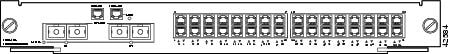
Front Panel Description
Figure 1 shows the front panel of the Layer 3 services module. The features of the front panel are described in more detail in the following sections.
Figure 1 Front Panel of the Layer 3 Services Module
LEDs
Table 3 describes the LEDs on the Catalyst 4000 Layer 3 Services module.
Table 3 LEDs on the Catalyst 4003 and 4006 Layer 3 Services Module
STATUS (module)
This LED displays the results of a series of self-tests and diagnostic tests performed by the switch.
Green
All the tests pass.
Red
A test other than an individual port test failed.
Orange
System boot, self-test diagnostics running, or the module is disabled.
LINK
This LED displays the 10/100 management port status.
Green
A signal is detected.
Off
No signal is detected.
Port Number
G1 and G21These LEDs display individual Gigabit Ethernet port status.
Green
A 1000-mbs link is detected.
Off
No signal is detected.
Port Number 3-341
These LEDs display individual 10/100 Ethernet port status.
Green
A 100-mbs link is detected.
Orange
A 10-mbs link is detected.
Off
No signal is detected.
1 Each port has an LED labeled with the port number associated with it. This is the link LED that indicates port status
Connectors
Table 4 lists the front panel connectors on the Catalyst 4000 Layer 3 Services module.
Table 4 Front Panel Connectors on the Catalyst 4003 and 4006 Layer 3 Services Module
Console
RJ-45
10/100MGT
RJ-45
10/100BASE-TX
RJ-45
1000BASE-X
SC
Specifications
Table 5 lists the specifications for the Catalyst 4000 Layer 3 Services module.
Table 5 Catalyst 4003 and 4006 Layer 3 Services Module Specifications
Dimensions (H x W x D)
1.18 x 15.51 x 16.34 in. (30 x 394 x 415 mm)
Weight
Minimum: 3 lb. (1.36 kg)
Maximum: 5 lb. (2.27 kg)Environmental conditions:
Operating temperature
32 to 104°F (0 to 40°C)
Nonoperating temperature
-40 to 167°F (-40 to 75°C)
Humidity
10 to 90%, noncondensing
Maximum station-to-station cabling distance:
328 ft. (100 m), half or full duplex
Console: Categories 3-5 UTP and 100-ohm FTP
328 ft. (100 m)
10/100BASE-TX Ethernet: Category 5 UTP and 100-ohm FTP
328 ft. (100 m), half or full duplex
1000BASE-X
See Table 7
Frame processing
Transparent bridging (IEEE 802.1d)
Network management
Cisco Discovery Protocol, Ethernet MIB (RFC 1398), Interface Table (RFC 1573), Bridge MIB (RFC 1493), Ethernet Repeater MIB (RFC 1516), RMON MIB (RFC 1757), Cisco Workgroup MIB, and Cisco VLAN Trunking Protocol
1 UTP = unshielded twisted-pair
2 FTP = foil twisted-pair
Standards Compliance Specifications
When properly installed in the chassis, the Catalyst 4000 Layer 3 Services module complies with the standards listed in Table 6.
Table 6 Standards Compliance
Compliance:
CE Marking
Safety
UL1 1950, CSA2 -C22.2 No. 950, EN3 60950, IEC4 950, TS5 001, AS/NZS6 3260
EMI7
CFR 47, Part 15, class A (FCC),8 ICES 003 class A, 9 EN55022, class A with UTP,10 EN55022, class B with FTP,11 CISPR 22, class A with UTP, CISPR 22, class B with FTP, AS/NZ 3548, class A with UTP, AS/NZ 3548, class B with FTP, VCCI, class A with UTP,12 VCCI, class B with FTP, EN55024, CE marking.
1 UL = Underwriters Laboratories
2 CSA = Canadian Standards Association
3 EN = Europäische Norm
4 IEC = International Electrotechnical Commission
5 TS = Technical Standard
6 AS/NZS = Australian/New Zealand Standard
7 EMI = electromagnetic interference
8 FCC = U.S. Federal Communications Commission
9 ICES = Interference-Causing Equipment Standard
10 UTP = unshielded twisted-pair
11 FTP = foil twisted-pair
12 VCCI = Voluntary Control Council for Information Technology Equipment
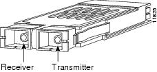
Gigabit Interface Converters
A gigabit interface converter (GBIC), shown in Figure 2, is a hot-swappable I/O (transceiver) device that plugs into the module's Gigabit Ethernet port, linking the port with the fiber-optic network. The following GBIC types are supported:
•
•
•
Figure 2 Gigabit Interface Converter
Note
Note
GBIC Cabling Distances
Table 7 lists the recommended maximum station-to-station cabling distances for the supported types of GBICs.
Table 7 GBIC Station-to-Station Cabling Distances
SX
850
MMF1
62.5
160
722 ft. (220 m)
62.5
200
902 ft. (275 m)
50.0
400
1640 ft. (500 m)
LX/LH
1300
MMF1
SMF2
62.5
62.5
50.0
50.0
9/10
500
500
400
500
-
1804 ft. (550)
1804 ft. (550)
1804 ft. (550)
1804 ft. (550)
6.2 mi(10 km)
ZX
1550
SMF2
SMF3
9/10
8
-
-
43.5 mi (70 km)
62.1 mi (100 km)
1 MMF=multimode fiber
2 SMF=single-mode fiber
3 A dispersion-shifted single-mode fiber-optic cable is required for 62.1 mi (100 km) distance
Note
GBIC Optical Power Characteristics
Table 8 provides the optical power characteristics of the GBIC.
GBIC Cabling Restrictions
You must observe the following optical-fiber cabling restrictions when using GBICs:
•
•
•
•
Safety Overview
Safety warnings appear throughout this publication in procedures that, if performed incorrectly, may harm you. A warning symbol precedes each warning statement.
Warning
Warning
Warning
Warning
Warning
Warning
Warning
Warning
Warning
Warning
Warning
Translated Safety Warnings
This section translates in multiple languages the warnings for the Catalyst 4000 Layer 3 Services module.
Warning Definition
Safety Information Referral Warning
Qualified Personnel Warning
Blank Faceplate Installation Requirement Warning
Invisible Laser Radiation Warning (other versions available)
Removing and Installing a Layer 3 Services Module
The following sections describe how to remove and install modules, GBICs, and cables:
•
•
Catalyst 4003 and 4006 switches support hot swapping, which lets you install, remove, replace, and rearrange modules without turning off the system power. When the system detects that a module has been installed or removed, it runs diagnostic and discovery routines automatically, acknowledges the presence or absence of the module, and resumes system operation with no operator intervention.
Warning
Warning
Required Tools
You will need these tools to install modules in the Catalyst 4003 and Catalyst 4006 switches:
•
•
•
Caution
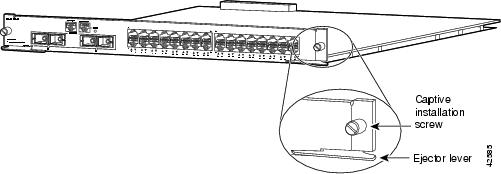
Removing Modules
You might need to remove a module from the switch chassis to make room for the Layer 3 services module. To remove a module from a Catalyst 4003 or Catalyst 4006 switch, perform these steps:
Step 1
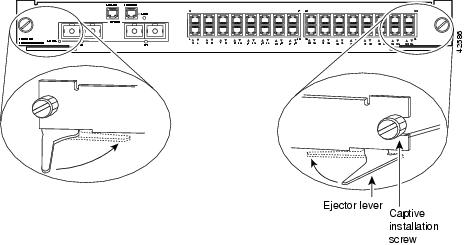
Step 2
Figure 3 Ejector Levers and Captive Installation Screws
Step 3
Step 4
Caution
Step 5
Step 6
Step 7
Step 8
Warning
You have now completed the removal of a module from a Catalyst 4003 or Catalyst 4006 switch.
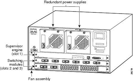
Installing the Layer 3 Services Module
All Catalyst 4003 and Catalyst 4006 modules are installed in horizontal chassis slots that are numbered from top to bottom. Supervisor engines are installed in slot 1; modules are installed in the remaining slots. Figure 4 shows an example of a supervisor engine and two modules installed in a Catalyst 4003 switch.
Figure 4 Module Placement in a Catalyst 4003 Switch
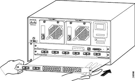
To install the Catalyst 4000 Layer 3 Services module in a Catalyst 4003 or Catalyst 4006 switch, perform these steps:
Step 1
Step 2
Step 3
Figure 5 Catalyst 4003: Installing the Module in the Chassis
Step 4
Step 5
Step 6
Caution
Figure 6 Module Ejector Lever Operation
Step 7
You have now completed the installation of a module in to a Catalyst 4003 or Catalyst 4006 switch.
Installing a GBIC
This section describes how to install GBICs in the Catalyst 4000 Layer 3 Services module.
Handling a GBIC
When handling a GBIC, remember these facts:
•
•
•
Installing GBICs
GBICs are hot-swappable in the Catalyst 4000 Layer 3 Services module. GBICs have a lifetime of 100 to 500 removals and insertions, so to prevent premature failure of the GBIC, do not remove or insert the GBIC unnecessarily.
When removing or inserting a GBIC, always wear an ESD wrist strap connected to the Catalyst 4003 or Catalyst 4006 switch ESD wrist strap connector.
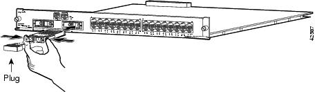
To install a GBIC, perform these steps:
Step 1
Step 2
Step 3
Note
Figure 7 Installing a GBIC in the Module
Step 4
Warning
Step 5
Note
You have now completed the installation of a GBIC in to a Catalyst 4003 or Catalyst 4006 module.
Mode-Conditioning Patch Cord
When using the LX/LH GBIC with 62.5-micron diameter MMF, you must install a mode-conditioning patch cord (Cisco product number CAB-GELX-625 or equivalent) between the GBIC and the MMF cable on both the transmit and receive ends of the link. The patch cord is required for link distances greater than 984 feet (300 meters). For more information on the patch cord, see the Catalyst 4003 and 4006 Switch Installation Guide.
The patch cord is required to comply with IEEE standards. The IEEE found that link distances could not be met with certain types of fiber-optic cable due to a problem in the center of some fiber-optic cable cores. The solution is to launch light from the laser at a precise offset from the center by using the patch cord. At the output of the patch cord, the LX/LH GBIC is compliant with the IEEE 802.3z standard for 1000BASE-LX. For a detailed description of this problem, refer to the Catalyst 4003 and 4006 Switch Installation Guide.
Note
Attaching Interface Cables to the Layer 3 Services Module
This section describes how to connect the interface cables to the installed Catalyst 4003 and 4006 Layer 3 Services module.
Attaching the Console Port Interface Cable
A console serial port (RJ-45) lets you manage your system using standard console equipment.
For RJ-45 connectors, plug the interface cable connector into the receptacle on the module. Push in the connector until you hear a click; the click indicates that the connector is fully inserted and secured in the receptacle.
Attaching the 10/100 MGT Port Cable
The 10/100BASE-T port (RJ-45) supports remote console interfaces. This port is for network management only. This port is not a switching port. There is no connectivity between this port and the Gigabit Ethernet switching ports.
For RJ-45 connectors, plug the interface cable connector into the receptacle on the module. Push in the connector until you hear a click; the click indicates that the connector is fully inserted and secured in the receptacle.
Attaching the GBIC Interface Cable
Warning
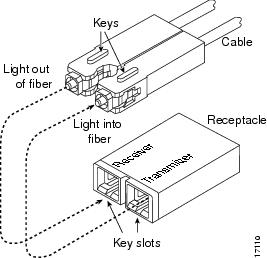
To connect GBICs to the Gigabit Ethernet or Gigabit EtherChannel ports, perform these steps:
Step 1
Step 2
Step 3
Figure 8 SC Type Connector
Attaching the 10/100 Interface Cables
For RJ-45 connectors, plug the interface cable connector into the receptacle on the module. Push in the connector until you hear a click; the click indicates that the connector is fully inserted and secured in the receptacle.
Accessing the Layer 3 Services Module for the First Time
This section explains how to access the Catalyst 4000 Layer 3 Services module, download an image to bootflash, download an image from the network, and perform an image recovery using Xmodem or Ymodem.
The Catalyst 4000 Layer 3 Services module is configured at the factory to automatically load a Cisco IOS image (router operating system software) the first time you insert the module into a Catalyst 4000 family switch. The module software configuration register, which determines where the Catalyst 4000 Layer 3 Services module loads the image from, is set at the factory to load the IOS image from bootflash (configuration register setting 0x2102). Table 9 shows the default configuration of the Catalyst 4000 Layer 3 Services module.
Table 9 Default Configuration of the Catalyst 4003 and 4006 Layer 3 Services Module
Host name
Router
Interface configuration
None
VLAN configuration1
None
Password encryption
Disabled
Break to console
Ignore
1 You must configure VLAN 1 to be the default VLAN on both the Catalyst 4000 Layer 3 Services module and the Supervisor Engine
Accessing the Module Console
After the Catalyst 4000 Layer 3 Services module goes through power-on self-test diagnostics, and the front panel STATUS LED is green, you can access the Catalyst 4000 Layer 3 Services module console in these two ways:
•
•
When you access the Catalyst 4000 Layer 3 Services module for the first time, you need to configure the module is internal interfaces and then save the configuration to a file in NVRAM. From the router console, configure the two external Layer 3 ports for access to another device and configure the two internal ports as trunks, as an EtherChannel, or as independent links to connect through the backplane to the Layer 2 ports in the Catalyst 4000 switch.
Connecting Through the Module Console Port
The console port allows you to access the Catalyst 4000 Layer 3 Services module either locally (with a console terminal) or remotely (with a modem). The console port is an EIA/TIA-232 asynchronous, serial connection with an RJ-45 connector.
For complete console port cabling specifications and pinouts, refer to the Catalyst 4003 and 4006 Switch Installation Guide.
The console port mode switch allows you to connect a terminal to the Catalyst 4000 Layer 3 Services module using the console cable provided with a Catalyst 4000 family switch. You can also connect a modem to the console port using the cable and adapter provided with the switch.
Put the port mode switch in the "in" position (factory default position) to connect a terminal to the console port using the console cable and data terminal equipment (DTE) adapter (labeled "Terminal"). The console cable and the DTE adapter shipped with the switch.
Note
Also, when the port mode switch is in the "in" position you can connect a modem to the console port using the console cable and data communications equipment (DCE) adapter (labeled "Modem") that shipped with the switch.
Note
Note
Connecting a Terminal
To connect a terminal to the console port using the cable and adapters provided with the
Catalyst 4000 family switch, ensure that the console port mode switch is in the "in" position (factory default position). Connect to the port using the RJ-45-to-RJ-45 cable and RJ-45-to-DB-25 DTE adapter or RJ-45-to-DB-9 DTE adapter (labeled "Terminal").Check the documentation that came with your terminal to determine the baud rate. The baud rate of the terminal must match the default baud rate (9600 baud) of the console port.
Set up the terminal using the following specifications:
•
•
•
•
•
Connecting a Modem
To connect a modem to the console port, ensure that the console port mode switch is in the "in" position (factory default position). Connect the modem to the port using the RJ-45-to-RJ-45 cable and the RJ-45-to-DB-25 DCE adapter (labeled "Modem").
Configuring the Management Port
You can download an image to the Catalyst 4000 Layer 3 Services module through the 10/100 management interface by assigning it an IP address.
To configure an IP address on the management port and configure it for Telnet access, perform this procedure:
This example shows you how to assign an IP address to the Catalyst 4000 Layer 3 Services module 10/100 management port:
Router#configure terminalEnter configuration commands, one per line. End with CNTL/Z. Router(config)# interface F1 Router(config-if)# ip address 131.108.1.27 255.255.255.0 Router(config-if)# no shutdown Router(config-if)# exit Router(config)# line vty 0 Router(config-line)#password 7 Cisco Router(config-line)# endRouter#copy running-config
Note
You can also download images and configuration files to the Catalyst 4000 Layer 3 Services module through one of the Gigabit Ethernet routing ports. If you choose to manage the Layer 3 Services module through a Gigabit Ethernet routing port, any IP address assigned to the corresponding interface can be used for network management purposes when the port is up.
SNMP Network Management
The supervisor engine reports one IP address assigned to the Layer 3 Services module that can be used for network management through the Cisco Stack MIB. If you are using CiscoView to manage your Catalyst 4000 switch, you can also manage the Catalyst 4000 Layer 3 Services module with this software.
If the 10/100 management interface is up and an IP address has been configured, the Layer 3 Services module selects the IP address assigned to the 10/100 management port. If the management port is down or an IP address has not been configured, the module randomly selects an IP address that has been assigned to one of the Gigabit Ethernet ports or port channels as the network management IP address, provided the interface associated with this IP address is up at the time of selection.
If the selected network management IP address is removed or the interface or subinterface associated with this IP address is shut down, the Layer 3 Services module selects another IP address as a replacement.
If all the interfaces are down or no IP address has been assigned to any interface or subinterface that is up, the IP address for network management is 0.0.0.0.
After each IP address selection or change of the IP address, the Layer 3 Services module sends an unsolicited message to the supervisor engine, which then populates the IP address attribute of the Cisco Stack MIB entry of the Catalyst 4000 Layer 3 Services module.
Recovering an Image Using Xmodem or Ymodem
Caution
You can download an image from a local or remote computer (such as a PC, UNIX workstation, or Macintosh) through the console port using the Xmodem or Ymodem protocol. Xmodem and Ymodem are common protocols used to transfer files and are included in applications such as Windows 3.1 (TERMINAL.EXE), Windows 95 (HyperTerminal), Windows NT 3.5x (TERMINAL.EXE), Windows NT 4.0 (HyperTerminal), and Linux UNIX freeware (minicom).
Xmodem and Ymodem downloads are slow. You can speed up the transfer by setting the console port speed to 57600 bps.
Perform Xmodem file transfers from the ROM monitor with the following command:
xmodem [-cys] [-c  CRC-16] [-y  ymodem-batch protocol]-s<speed> Set speed of download,
where speed may be 1200|2400|4800|9600|19200|38400|57600]
The computer from which you transfer the supervisor engine software image must be running terminal emulation software that supports the Xmodem protocol.
Caution
To transfer a file using Xmodem or Ymodem protocol, perform these steps:
Note
Step 1
Step 2
Step 3
Step 4
Step 5
xmodem -y -s57600
The ROMMON will return with a question asking whether you accept 57600 as the download speed. Press <Enter> to accept and proceed.
Step 6
a.
b.
c.
Step 7
Step 8
Step 9
Step 10
Step 11
After you have completed this procedure, ROMMON boots the image that has been transferred. You may need to recover the bootflash by reformatting the IOS image after it has been loaded. To reform the bootflash use the ROMMON format bootflash command.
Upgrading Images
Network downloads take place over the out-of-band Ethernet management port or over the internal Gigabit Ethernet connections. To perform a network download over the internal Gigabit Ethernet connections, you must first configure and bring up these connections.
You can configure the Catalyst 4000 Layer 3 Services module to download its runtime image from a TFTP server and to load images to bootflash. No supervisor engine interaction is required for TFTP image downloads.
Note
To download an image to bootflash, access the Catalyst 4000 Layer 3 Services module using the session command and enter the following command in privileged mode:
Router># copy tftp bootflash:Overview of the Catalyst 4003 and 4006 Layer 3 Services Module Interfaces
The Catalyst 4000 Layer 3 Services module supports two external and two internal Layer 3 Gigabit Ethernet interfaces, which run IOS software, and 32 10/100 Layer 2 ports, which are configurable from the supervisor engine.
You can map all Layer 2 ports on the Catalyst 4000 family switch with VLANs and trunks to the Layer 3 interfaces on the Catalyst 4000 Layer 3 Services module.
To configure the Layer 3 interfaces, you must first access the Catalyst 4000 Layer 3 Services module through a direct terminal connection or by entering the session command from the supervisor engine prompt. You must configure the internal Gigabit Ethernet ports from the supervisor engine to match their associated Layer 2 ports. To configure the Catalyst 4000 Layer 3 Services module, use the Layer 3 console. To configure the Layer 2 ports, use the switch console. This section provides information on how to configure both the external and internal Gigabit Ethernet ports.
You must configure and add Layer 2 ports to your VLANs before the Catalyst 4000 Layer 3 Services module can route traffic from the Layer 2 ports on the Catalyst 4000 family switch.
Understanding Key Features
This section describes the key features supported in Layer 3 switching software.
Distributed Hardware Forwarding
Layer 3-switching software uses a distributed architecture in which the control path and data path are relatively independent. The control path code, such as routing protocols, runs on the processor; the data packets are switched by the Ethernet interfaces and the switching fabric.
A microcoded application-specific integrated circuit (ASIC) handles all packet switching for the interfaces. The following are the main functions of the control layer between the routing protocol and the firmware data path microcode:
•
•
•
•
Cisco IOS Routing Protocols
Layer 3-switching software provides a comprehensive suite of routing protocols based on Cisco IOS software. The following networking protocols and routing protocols are supported on the Catalyst 4000 Layer 3 Services module.
Table 10 Supported Networking and Routing Protocols
IP
RIP, RIP-2, OSPF, IGRP, EIGRP, PIM, BGP
IPX
IPX RIP, EIGRP
Many of the Cisco IOS routing protocol features, such as route redistribution and load balancing over equal cost paths (for OSPF and EIGRP), are supported. The methods used to configure these routing protocols is identical to the configuration methods currently employed on all Cisco routers.
Note
Caution
QoS-Based Forwarding
QoS includes technologies such as weighted round-robin scheduling, policing, and shaping, which help control bandwidth, network delay, jitter, and packet loss in congested networks. The QoS identifier provides specific treatment to traffic in different classes, so that each class receives different QoS.
The class to which the packets belong determines packet scheduling and discarding policies. For example, the overall service given to packets in the premium class will be better than that given to the standard class; the premium class is expected to experience lower loss rate or delay.
The switch router has QoS-based forwarding for IP traffic only. The implementation of QoS forwarding is based on local administrative policy and IP precedence. The mapping between the IP precedence field and the QoS field determines the delay priority of the packet.
For more information about QoS, see the "Configuring Layer 3 QoS" section
Caution
Network Class Redundancy
The redundancy of Cisco IOS software provides key network features, such as HSRP, routing protocol convergence with RIP, OSPF, EIGRP, EtherChannel, and load sharing across equal cost Layer 3 paths and spanning trees (for Layer 2-based networks).
Remote Monitoring
Layer 3 switching software supports the first four Remote Monitoring (RMON) groups.
RMON is a network management protocol for gathering network information and monitoring traffic data within remote LAN segments from a central location. RMON allows you to monitor all nodes and their interaction on a LAN segment. RMON, used with the SNMP agent in the switch router, allows you to view both the traffic that flows through the router and segment traffic not necessarily destined for the switch router. Layer 3-switching software combines RMON alarms and events with existing MIBs so you can choose where monitoring will occur.
Refer to the Cisco IOS Configuration Fundamentals Configuration Guide for more information about RMON.
Cisco Discovery Protocol
CDP is a device-discovery protocol that is both media and protocol independent. CDP is available on all Cisco products, including routers, switches, bridges, and access servers. Using CDP, a device can advertise its existence to other devices and receive information about other devices on the same LAN. CDP enables Cisco products to exchange information with each other regarding their MAC addresses, IP addresses, and outgoing interfaces. CDP runs over the data link layer only, which allows two systems that support different network-layer protocols to learn about each other. Each device configured for CDP sends periodic messages to a multicast address. Each device advertises at least one address at which it can receive Simple Network Management Protocol (SNMP) messages.
Cisco Express Forwarding
Layer 3-switching software features CEF. CEF is advanced Layer 3 IP-switching technology. CEF optimizes network performance and scalability for networks with large and dynamic traffic patterns, such as the Internet, on networks characterized by intensive Web-based applications, or interactive sessions. Although you can use CEF in any part of a network, it is designed for high-performance, highly resilient Layer 3 IP-backbone switching.
CEF manages route distribution and forwarding by distributing routing information from the central processor to the individual Ethernet interfaces. This technology, used within the Internet, provides scalability in large campus core networks. CEF provides Layer 3 forwarding based on a topology map of the entire network, resulting in high-speed routing table lookups and forwarding.
One of the key benefits of CEF in Layer 3 switching is its routing convergence. Because the FIB is distributed to all interfaces, whenever a route goes away or is added, the FIB updates that information and provides it to the interfaces. Central processor interrupts are minimized. The interfaces receive the new topology very quickly and reconverge around a failed link based on the routing protocol being used.
Caution
Load Balancing
A switch router that employs load balancing can distribute traffic over all its network ports that are the same distance from the destination address. Load balancing increases the utilization of network segments and increases effective network bandwidth.
Layer 3-switching software uses source + destination-based load balancing, an enhanced version of the Cisco IOS software is per-destination load balancing. This method takes certain bits from the source and destination IP and IPX addresses and maps them into a path.
This method has these benefits:
•
•
Layer 3-switching software supports load balancing on equal cost paths using the source and destination IP or IPX address. The Catalyst 4003 or 4006 Layer 3 Services module uses two equal cost paths. Per-packet load balancing is not supported.
Optionally, if you are load balancing a Gigabit Ethernet port you may configure the port to load balance using CEF.
CEF load balancing decisions are made on the ingress interface. Load distortions may occur across multiple switch routers when the same CEF load balancing algorithm is used on every switch router. You can resolve these distortions by selecting a specific CEF load balancing algorithm, such as tunnel or universal, based on your network environment. The tunnel and universal algorithms are available on Gigabit Ethernet ports only.
Hot Standby Router Protocol
The HSRP provides high network availability by routing IP traffic from hosts on Ethernet networks without relying on the availability of any single switch router. This feature is particularly useful for hosts that do not support a router discovery protocol and do not have the functionality to switch to a new router when their selected router reloads or loses power.
Devices that are running HSRP detect a failure by sending and receiving multicast User Datagram Protocol (UDP) "hello" packets. When HSRP detects that the designated active router has failed, the selected backup router assumes control of the HSRP group's MAC and IP addresses. (You can also select a new standby router at that time.)
The chosen MAC address and IP addresses are unique and do not conflict with any others on the same network segment. The MAC address is selected from a pool of Cisco MAC addresses. Configure the last byte of the MAC address by configuring the HSRP group number. You also configure the unique virtual IP address. The IP address must be specified on a single router within the same group. When the HSRP is running, it selects an active router and instructs its device layer to listen on an additional (dummy) MAC address.
Layer 3-switching software supports HSRP over 10/100 Ethernet, Gigabit Ethernet, and GEC.
Gigabit EtherChannel
GEC allows grouping of gigabit ports into a single multigigabit logical EtherChannel link. GEC establishes a high-bandwidth connection between two Catalyst switch routers.
You can bundle up to two Gigabit Ethernet connections on the Catalyst 4000 Layer 3 Services module as one logical link, which can provide up to 4-Gb aggregate capacity. If a failure of any one link is detected, the packets are switched on the remaining active link in the GEC.
GEC uses a source-destination IP and IPX address load-balancing scheme for up to two ports in a channel group on the Catalyst 4003 and 4006 Layer 3 Services module. Each channel group has its own IP address.When you queue a packet to exit out of the port channel interface, the last two bits of the IP source and destination address determine which interface in the channel the packet takes.
As with all EtherChannel technologies, all links share the traffic load within the bundled ports.
For more information about GEC, see the "Configuring the Layer 3 Gigabit Ethernet Ports" section.
Spanning Tree Protocol
STP is a bridge protocol that enables a learning bridge to dynamically work around loops in a network topology by creating a spanning tree. Bridges exchange BPDU messages with other bridges to detect loops and then remove the loops by shutting down selected bridge interfaces.
STP maintains a network of multiple bridges or switches. When the topology changes, the STP transparently reconfigures bridges and switches to avoid the creation of loops by placing ports in a forwarding or blocking state. Each bridge group has a separate instance of the STP.
STP parameters are set for each bridge group. For each spanning tree instance, you configure a set of global options with a set of port parameters. The port parameter list contains only ports that are members of a given bridge group. The Layer 3 switch routers support a maximum of 16 bridge groups, which run their own instance of spanning tree.
Virtual LANs
A VLAN configures switches and routers according to logical rather than physical topologies. Using VLANs, a network administrator can combine any collection of LAN segments within an internetwork into an autonomous user group, which appears as a single LAN. VLANs logically segment the network into different broadcast domains so that packets are switched only between ports within the VLAN. Typically, a VLAN corresponds to a particular subnet, although not necessarily.
For information about InterVLAN routing, see the "Configuring the Module for InterVLAN Routing" section.
IEEE 802.1Q VLAN Encapsulation
802.1Q VLAN encapsulation uses a one-level, packet tagging scheme to multiplex VLANs across a single physical link, while maintaining strict adherence to the individual VLAN domains. 802.1Q can have access ports or untagged ports where frames are assigned to VLANs based on a port VLAN identifier (PVID), or native VLAN for the port. It can also have trunked ports where some frames can be tagged and others untagged. 802.1Q uses Per VLAN Spanning Tree Plus (PVST+), mapping multiple spanning trees to the spanning tree of pure 802.1Q switches.
IEEE 802.1Q VLAN encapsulation is supported over the internal and external gigabit router ports. See Figure 10 as an example on how to set up VLAN encapsulation.
For more information about 802.1Q on internal VLAN trunks, see the "Configuring 802.1Q Layer 2 VLAN Trunks" section.
Inter-Switch Link VLAN Encapsulation
Layer 3-switching software also supports Inter-Switch Link (ISL) encapsulation over the external Gigabit Ethernet ports or if configured as a GEC. The Catalyst 4003 and 4006 Layer 3 Services module can be deployed in environments with the ISL trunking protocol and can route between external gigabit ports running ISL and internal gigabit ports running 802.1Q stations.
External ports support ISL, which use one PVST+ over ISL trunks.
Switching Database Manager
Layer 3-switching software supports SDM. SDM resides on the central processor and its primary function is to maintain the Layer 3-switching database in ternary TCAM. SDM maintains the address entries contained in TCAM in an appropriate order. SDM manages TCAM space by partitioning protocol-specific switching information into multiple regions.
The key benefit of SDM in Layer 3 switching is its ability to configure the size of the protocol regions in TCAM. SDM enables exact-match and longest-match address searches, which result in high-speed forwarding.
For more information about SDM, see the "Configuring the Switching Database Manager" section.
Access Control Lists
ACLs allow you to filter packet flow into or out of switch router interfaces. ACLs are sometimes called filters. You can use ACLs to restrict network use by certain users or devices. ACLs are created for each protocol and applied on the interface either for inbound or outbound traffic. They can be configured for all routed network protocols (IP or Novell IPX) to filter packets for the protocol as they pass through a switch router. Only one ACL can be applied per protocol per (sub)interface in each direction.
When creating ACLs, you define criteria to apply to each packet processed by the switch router; the switch router decides whether to forward or block the packet based on whether or not the packet matches the criteria in your list. Packets that do not match any criteria in your list are automatically blocked by the implicit "deny all traffic" criteria statement at the end of every access list.
The specific instructions for creating ACLs and applying them to interfaces vary from protocol to protocol. Configuration of Layer 3-switching ACLs is identical to the configuration methods currently employed on all Cisco routers.
ACL functionality is built into Gigabit Ethernet ports of the Catalyst 4000 Layer 3 Services module. However, ACLs are not supported GEC. For more information on ACLs, see the "Configuring Access Control Lists" section.
Traffic that is switched by interface modules does not support ACL logging. However, ACL logging is supported for all traffic that goes to the CPU.
The enhanced Gigabit Ethernet interface module supports a TCAM size of 32K (32-bit) entries. The combined size of the protocol regions and access lists should not exceed your TCAM space. The default size of the access lists in a 32K TCAM is 512 (128-bit) entries. Before you configure the access list, make sure that TCAM has enough space to accommodate the access list.
IEEE 802.1Q VLAN Bridging
Layer 3-switching software supports 802.1Q bridging over Gigabit Ethernet and GEC. The Catalyst 4000 Layer 3 Services module can be deployed in environments with the 802.1Q trunking protocol and can bridge between ISL and 802.1Q stations.
Local Proxy ARP
The Local Proxy ARP feature allows the Catalyst 4000 Layer 3 Services module to respond to ARP requests for IP addresses within a subnet where normally no routing is required. With the local proxy ARP feature enabled, the Catalyst 4000 Layer 3 Services module responds to all ARP requests for IP addresses within the subnet and forwards all traffic between hosts in the subnet. Use this feature only on subnets where hosts are intentionally prevented from communicating directly by the configuration on the switch to which they are connected.
The local proxy ARP feature is disabled by default. Use the ip local-proxy-arp interface configuration command to enable the local proxy ARP feature on an interface. Use the no ip local-proxy-arp interface configuration command to disable the feature. ICMP redirects are disabled on interfaces where the local proxy ARP feature is enabled.
To use the local proxy ARP feature, the IP proxy ARP feature must be enabled. The IP proxy ARP feature is disabled by default. Refer to the Cisco IOS Release 12.0 Network Protocols Configuration Guide Part 1, "IP Addressing and Services," "Configuring IP Addressing," "Configure Address Resolution Methods," at: http://www.cisco.com/univercd/cc/td/doc/product/software/ios120/12cgcr/np1_c/1cprt2/1cipadr.htm
RADIUS Server
The RADIUS feature is a distributed client/server system that secures networks against unauthorized access. In the Cisco implementation, RADIUS clients run on Cisco routers and send authentication requests to a central RADIUS server that contains all user authentication and network service access information.
RADIUS is a fully open protocol, distributed in source code format, that can be modified to work with any security system currently available on the market.
Cisco supports RADIUS under its AAA security paradigm. RADIUS can be used with other AAA security protocols, such as TACACS+, Kerberos, or local username lookup. RADIUS is supported on all Cisco platforms. Refer to the Cisco IOS Release 12.0 Security Configuration Guide, "Security Server Protocols," "Configuring RADIUS," at: http://cisco.com/univercd/cc/td/doc/product/software/ios120/12cgcr/secur_c/scprt2/scrad.htm
Overview of the Layer 2 Interfaces
Assuming the Layer 3 Services module resides in slot 2, the port numbering is 2/1 and 2/2 for the internal Gigabit Ethernet ports, and 2/3 through 2/34 for the external 10/100 ports. Ports 2/3 through 2/34 are directly accessible via the external RJ-45 connectors. Ports 2/1 and 2/2 are internal ports and have no external interfaces.
Note
Overview of the Layer 3 Gigabit Ethernet Interfaces
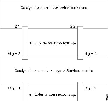
To the Catalyst 4000 family switch, the Layer 3 Services module appears to be an external router connected to the switch through two internal full-duplex Gigabit Ethernet ports.
The port numbering for the external Gigabit Ethernet interfaces on the front panel is Gigabit Ethernet1 and Gigabit Ethernet2. The port numbering for the internal Gigabit Ethernet interfaces is Gigabit Ethernet3 and Gigabit Ethernet4.
If the Layer 3 Services module is installed in slot 2, port 2/1 on the Catalyst switch side is connected to interface Gigabit Ethernet3 on the Catalyst 4000 Layer 3 Services module side and port 2/2 to interface Gigabit Ethernet4.
Figure 9 shows the internal interface connections when the Layer 3 Services module is installed in slot 6 in a Catalyst 4003 switch.
Figure 9 Internal Interface Connections
Configuration Options
You have the option to configure the Catalyst 4000 Layer 3 Services module ports as trunks, as EtherChannels, or as independent links. This section provides an overview of these three configuration options. For detailed configuration information, see the "Configuring the Module for InterVLAN Routing" section.
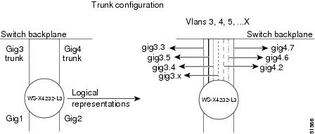
Option 1: Interfaces as Trunks (Recommended Option)
You can add Layer 2 ports to VLANs and group the VLANs into trunks. For the Layer 2 ports, you add the ports, from the switch console, to VLANs and then configure the trunks on the internal interfaces. When you enable trunking, you must configure a subinterface on the internal Layer 3 ports for each allowed VLAN configured on the Catalyst 4000 Layer 3 Services module trunk. The subinterface configuration is done on the internal Layer 3 ports from the
Catalyst 4000 Layer 3 Services module console. The trunking option requires you to configure the internal Layer 2 interfaces from the supervisor engine console as well as the internal Layer 3 ports from the Layer 3 Services module console. See Figure 10 for a conceptual illustration of trunking.Figure 10 Trunking
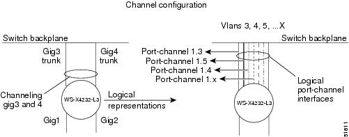
Option 2: Interfaces as Gigabit EtherChannels
The EtherChannel option builds on the previous trunk configuration when you assign trunks to a shared EtherChannel. After you create the EtherChannel between the Catalyst 4000 Layer 3 Services module and a Catalyst 4000 family switch, the channel provides Layer 3 services to one or multiple VLAN interfaces.
By bundling the two Catalyst 4000 Layer 3 Services module Gigabit Ethernet interfaces into one logical port-channel interface, you create a shared connection for traffic from the Layer 2 ports to the Layer 3 ports. You can configure Layer 3 VLAN gateways by creating multiple subinterfaces on the same logical interface. Creating subinterfaces on one logical interface is less complicated than manually distributing VLANs among multiple physical and logical interfaces on the Catalyst 4000 Layer 3 Services module. See Figure 11 for a conceptual illustration of channeling.
Figure 11 Channeling
Option 3: Interfaces as Independent Links
If your Catalyst 4000 switch has only a few VLANs, use the independent interface configuration option. When you are providing Layer 3 gateway services for only one or two VLANs, trunking is not necessary. The Catalyst 4000 Layer 3 Services module Gigabit Ethernet interface needs to be included only in the specific VLAN, just as you would include a host port. For example, if you need only two VLANs, configure these VLANs on the switch and add each to one of the internal interfaces. Access the Catalyst 4000 Layer 3 Services module console and add each Catalyst 4000 Layer 3 Services module interfaces to its respective VLAN. Assign an IP (or IPX) address to the corresponding Catalyst 4000 Layer 3 Services module routed interface (GigE3 or GigE4).
To provide Layer 3 gateway services for more than one VLAN on a Catalyst 4000 Layer 3 Services module Gigabit Ethernet interface, you must use VLAN trunking. You can use the 802.1Q VLAN trunking method to create the trunk between the Catalyst 4000 Layer 3 Services module interface and the switch.
Configuring the Layer 3 Services Module Gigabit Ethernet Interfaces
Note
To configure a Catalyst 4000 Layer 3 Services module Gigabit Ethernet interface, follow these steps:
Step 1
4232-L3> enable4232-L3# configure terminal4232-L3(config)#Step 2
4232-L3(config)# interface g34232-L3(interface-if)#Step 3
The commands you enter define the protocols and applications that will run on the interface. The module collects and applies commands to the interface command until you enter another interface command, enter a command that is not an interface configuration command, or press Ctrl-Z to return to privileged EXEC mode.
Step 4
4232-L3# show interface g3Gigabit Ethernet3 is up, line protocol is upHardware is xpif_port, address is 0050.3e7b.e907 (bia 0050.3e7b.e907)Internet address is 11.0.0.2/8MTU 1500 bytes, BW 1000000 Kbit, DLY 10 usec, rely 255/255, load 1/255Encapsulation ARPA, loopback not set, keepalive set (10 sec)Full-duplex, 1000Mb/s, GBIC connected, Force link-upARP type:ARPA, ARP Timeout 04:00:00Last input 03:27:17, output never, output hang neverLast clearing of "show interface" counters neverQueueing strategy:fifoOutput queue 0/40, 0 drops; input queue 0/75, 0 drops5 minute input rate 0 bits/sec, 0 packets/sec5 minute output rate 0 bits/sec, 0 packets/sec945 packets input, 320796 bytes, 0 no bufferReceived 0 broadcasts, 0 runts, 0 giants, 0 throttles0 input errors, 0 CRC, 0 frame, 0 overrun, 0 ignored, 0 abort0 watchdog, 927 multicast0 input packets with dribble condition detected943 packets output, 319527 bytes, 0 underruns(0/0/0)0 output errors, 0 collisions, 0 interface resets0 babbles, 0 late collision, 0 deferred0 lost carrier, 0 no carrier0 output buffer failures, 0 output buffers swapped out
Configuring an IP Address on a Gigabit Ethernet Interface
To configure an IP address on one of the external Gigabit Ethernet interfaces, perform the following task in global configuration mode:
Monitoring Operations on the Gigabit Ethernet Interfaces
To verify the settings after you have configured the Gigabit Ethernet interfaces, use the show interface command. The output from the show interface command shown below displays the interface status and global parameters and includes port speed and duplex operation:
4232-L3# show interface g3Gigabit Ethernet3 is up, line protocol is upHardware is xpif_port, address is 0050.3e7b.e907 (bia 0050.3e7b.e907)Internet address is 11.0.0.2/8MTU 1500 bytes, BW 1000000 Kbit, DLY 10 usec, rely 255/255, load 1/255Encapsulation ARPA, loopback not set, keepalive set (10 sec)Full-duplex, 1000Mb/s, GBIC connected, Force link-upARP type:ARPA, ARP Timeout 04:00:00Last input 03:27:17, output never, output hang neverLast clearing of "show interface" counters neverQueueing strategy:fifoOutput queue 0/40, 0 drops; input queue 0/75, 0 drops5 minute input rate 0 bits/sec, 0 packets/sec5 minute output rate 0 bits/sec, 0 packets/sec945 packets input, 320796 bytes, 0 no bufferReceived 0 broadcasts, 0 runts, 0 giants, 0 throttles0 input errors, 0 CRC, 0 frame, 0 overrun, 0 ignored, 0 abort0 watchdog, 927 multicast0 input packets with dribble condition detected943 packets output, 319527 bytes, 0 underruns(0/0/0)0 output errors, 0 collisions, 0 interface resets0 babbles, 0 late collision, 0 deferred0 lost carrier, 0 no carrier0 output buffer failures, 0 output buffers swapped outConfiguring the Module for InterVLAN Routing
These sections describe how to configure the Layer 3 Services module for interVLAN routing:
•
•
•
Note
Overview of InterVLAN Routing
Network devices in different VLANs cannot communicate with one another without a router to route traffic between the VLANs. In most network environments, VLANs are associated with individual networks or subnetworks.
For example, in an IP network, each subnetwork is mapped to an individual VLAN. In an IPX network, each VLAN is mapped to an IPX network number.
VLANs help to control the size of the broadcast domain and keep local traffic local. However, when an end station in one VLAN needs to communicate with an end station in another VLAN, interVLAN communication is required. This communication is supported by interVLAN routing. You configure one or more routers to route traffic to the appropriate destination VLAN.
This example shows you how would configure VTP on the Catalyst 4000 switch ports, create two VLANs, and assign switch ports to those VLANs:
Console> (enable) set vtp mode serverVTP domain modifiedConsole> (enable) set vtp domain Corp_NetVTP domain Corp_Net modifiedConsole> (enable) set vlan 100Vlan 100 configuration successfulConsole> (enable) set vlan 200Vlan 200 configuration successfulConsole> (enable) set vlan 100 3/1-12VLAN 100 modified.VLAN 1 modified.VLAN Mod/Ports---- -----------------------100 2/1-23/1-12Console> (enable) set vlan 200 3/13-24VLAN 200 modified.VLAN 1 modified.VLAN Mod/Ports---- -----------------------200 2/1-23/13-24Console> (enable)Configuration Overview
Note
You should view the Catalyst 4000 Layer 3 Services module as an external and internal router with two full-duplex Gigabit Ethernet interfaces. The recommended configuration is to trunk or channel the two Gigabit Ethernet interfaces. Another configuration option is to configure the interfaces independently. The following sections describe the three options and the autostate feature which powers the
Catalyst 4000 Layer 3 Services module.We recommend that you follow this sequence:
•
•
•
•
•
•
Configuring Layer 2 Ethernet and Gigabit Ethernet Ports
The following sections briefly describe how to configure the Layer 2 Ethernet and Gigabit Ethernet ports for interVLAN routing from the supervisor engine console. For complete information on Layer 2 port configuration, refer to the Software Configuration Guide for your switch.
•
•
•
•
•
Note
Overview of the Layer 2 Interfaces
The port numbering for the 10/100 ports is as follows: Assuming the Layer 3 Services module resides in slot 2, the port numbering is 2/1 and 2/2 for the internal Gigabit Ethernet ports and 2/3 through 2/34 for the external 10/100 ports. All Layer 2 ports in the Catalyst 4000 switch follow this port numbering convention.
Setting the VTP Domain
If the Catalyst 4000 Layer 3 Services module is installed in a new Catalyst 4000 family switch, you must set the VLAN Trunking Protocol (VTP) domain. You can configure the module to use VTP server mode, VTP client mode, or VTP transparent mode. Refer to the Software Configuration Guide for your switch for information about VTP. Setting the VTP domain is required to create VLANs.
VTP Server Mode
VTP server mode lets you change the VLAN configuration once and then have it propagate throughout the network.
To configure the switch as a VTP server, perform this task in privileged mode:
This example shows you how to configure the switch as a VTP server and verify the configuration:
Console> (enable) set vtp domain Lab_NetworkVTP domain Lab_Network modifiedConsole> (enable) set vtp mode serverVTP domain Lab_Network modifiedConsole> (enable) show vtp domainDomain Name Domain Index VTP Version Local Mode Password-------------------------------- ------------ ----------- ----------- ----------Lab_Network 1 2 server -Vlan-count Max-vlan-storage Config Revision Notifications---------- ---------------- --------------- -------------10 1023 40 enabledLast Updater V2 Mode Pruning PruneEligible on Vlans--------------- -------- -------- -------------------------172.20.52.70 disabled disabled 2-1000Console> (enable)VTP Client Mode
You cannot change the VLAN configuration on the switch when it is in VTP client mode. A switch in client mode receives VTP updates from a VTP server in the management domain and modifies its configuration accordingly.
To configure the switch as a VTP client, perform these tasks in privileged mode:
This example shows you how to configure the switch as a VTP client and verify the configuration:
Console> (enable) set vtp domain Lab_NetworkVTP domain Lab_Network modifiedConsole> (enable) set vtp mode clientVTP domain Lab_Network modifiedConsole> (enable) show vtp domainDomain Name Domain Index VTP Version Local Mode Password-------------------------------- ------------ ----------- ----------- ----------Lab_Network 1 2 client -Vlan-count Max-vlan-storage Config Revision Notifications---------- ---------------- --------------- -------------10 1023 40 enabledLast Updater V2 Mode Pruning PruneEligible on Vlans--------------- -------- -------- -------------------------172.20.52.70 disabled disabled 2-1000Console> (enable)VTP Transparent Mode
Configure the switch as VTP transparent to disable VTP on the switch. A VTP transparent switch does not send VTP updates and does not act on VTP updates received from other switches. However, a VTP transparent switch running VTP version 2 does forward received VTP advertisements out all of its trunk links.
To disable VTP on the switch, perform these tasks in privileged mode:
This example shows you how to configure the switch as VTP transparent and verify the configuration:
Console> (enable) set vtp mode transparentVTP domain Lab_Net modifiedConsole> (enable) show vtp domainDomain Name Domain Index VTP Version Local Mode Password-------------------------------- ------------ ----------- ----------- ----------Lab_Net 1 2 Transparent -Vlan-count Max-vlan-storage Config Revision Notifications---------- ---------------- --------------- -------------10 1023 0 enabledLast Updater V2 Mode Pruning PruneEligible on Vlans--------------- -------- -------- -------------------------172.20.52.70 disabled disabled 2-1000Console> (enable)Setting the Layer 2 Port Speed
You can configure the port speed on 10/100 Ethernet ports. Use the auto keyword to have the port autonegotiate speed and duplex mode with the neighboring port.
Caution
Note
To set the port speed for a 10/100-Mbps port, perform these tasks in privileged mode:
This example shows you how to set the port speed to 100 Mbps on port 2/4:
Console> (enable) set port speed 2/4 100Port 2/4 speed set to 100 Mbps.Console> (enable)This example shows you how to make port 2/4 autonegotiate speed and duplex with the neighbor port:
Console> (enable) set port speed 2/4 autoPort 2/4 speed set to auto-sensing mode.Console> (enable)Setting the Layer 2 Port Duplex Mode
You can set the port duplex mode to full or half duplex for 10/100-Mbps Ethernet ports.
Note
To set the duplex mode of a port, perform these tasks in privileged mode:
This example shows you how to set the duplex mode to half duplex on port 2/4:
Console> (enable) set port duplex 2/4 halfPort 2/4 set to half-duplex.Console> (enable)Configuring VLANs
After you have configured VTP and specified the Layer 2 interface speed and duplex parameters, you must create VLANs and assign the ports to the VLANs.
Creating an Ethernet VLAN
To create a new Ethernet VLAN, perform these tasks in privileged mode:
Note
This example shows you how to create an Ethernet VLAN and verify the configuration:
Console> (enable) set vlan 4 name EngineeringVlan 4 configuration successfulConsole> (enable) show vlan 4VLAN Name Status IfIndex Mod/Ports, Vlans---- -------------------------------- --------- ------- ------------------------4 Engineering active 344VLAN Type SAID MTU Parent RingNo BrdgNo Stp BrdgMode Trans1 Trans2---- ----- ---------- ----- ------ ------ ------ ---- -------- ------ ------4 enet 100500 1500 - - - - - 0 0VLAN AREHops STEHops Backup CRF---- ------- ------- ----------Console> (enable)To modify the VLAN parameters on an existing Ethernet VLAN, perform this task in privileged mode:
Assigning Layer 2 Switch Ports to a VLAN
A VLAN created in a management domain remains unused until you assign one or more switch ports to the VLAN. If you specify a VLAN that does not exist, the VLAN is created and the specified ports are assigned to it.
To assign one or more switch ports to a VLAN, perform this task in privileged mode:
Step 1
Assign one or more switch ports to a VLAN.
set vlan vlan_num mod_num/port_num
Step 2
Verify the port VLAN membership.
show vlan [vlan_num]
show port [mod_num[/port_num]]This example shows you how to assign switch ports to a VLAN and verify the assignment:
Console> (enable) set vlan 4 2/1VLAN 4 modified.VLAN 1 modified.VLAN Mod/Ports---- -----------------------4 2/1Console> (enable) show vlan 4VLAN Name Status IfIndex Mod/Ports, Vlans---- -------------------------------- --------- ------- ------------------------4 Engineering active 59 2/1VLAN Type SAID MTU Parent RingNo BrdgNo Stp BrdgMode Trans1 Trans2---- ----- ---------- ----- ------ ------ ------ ---- -------- ------ ------4 enet 100500 1500 - - - - - 0 0VLAN AREHops STEHops Backup CRF---- ------- ------- ----------Console> (enable) show port 2/1Port Name Status Vlan Level Duplex Speed Type----- ------------------ ---------- ---------- ------ ------ ----- ------------2/1 notconnect 4 normal full 1000 1000BaseSXPort Security Secure-Src-Addr Last-Src-Addr Shutdown Trap IfIndex----- -------- ----------------- ----------------- -------- -------- -------2/1 disabled No disabled 12Port Status Channel Channel Neighbor Neighbormode status device port----- ---------- --------- ----------- ------------------------- ----------2/1 notconnect auto not channelPort Align-Err FCS-Err Xmit-Err Rcv-Err UnderSize----- ---------- ---------- ---------- ---------- ---------2/1 - 0 0 0 0Port Single-Col Multi-Coll Late-Coll Excess-Col Carri-Sen Runts Giants----- ---------- ---------- ---------- ---------- --------- --------- ---------2/1 0 0 0 0 0 0 0Last-Time-Cleared--------------------------Wed Jul 26 2000, 19:44:05Console> (enable)Configuring 802.1Q Layer 2 VLAN Trunks
A trunk is a point-to-point link between one device, such as a router or a switch, and another device. Trunks carry the traffic of multiple VLANs over a single link and allow you to extend VLANs across an entire network.
IEEE 802.1Q is an industry-standard trunking encapsulation that is available on all Ethernet ports.
You can configure a trunk on a single Ethernet port or on an EtherChannel bundle. For more information about EtherChannel, see the "Configuring EtherChannel" section.
Configuring an 802.1Q Trunk on Ethernet Ports
To configure an 802.1Q trunk, perform these tasks in privileged mode:
This example shows you how to configure an 802.1Q trunk and how to verify the trunk configuration:
Console> (enable) set trunk 2/1 desirable dot1qPort(s) 2/1 trunk mode set to desirable.Port(s) 2/1 trunk type set to dot1q.Console> (enable) 07/02/1998,18:22:25:DTP-5:Port 2/1 has become dot1q trunkConsole> (enable) show trunkPort Mode Encapsulation Status Native vlan-------- ----------- ------------- ------------ -----------2/1 desirable dot1q trunking 1Port Vlans allowed on trunk-------- ---------------------------------------------------------------------2/1 1-1005, 1025-4094Port Vlans allowed and active in management domain-------- ---------------------------------------------------------------------2/1 1,5,10-32,101-120,150,200,250,300,400,500,600,700,800,900,1000Port Vlans in spanning tree forwarding state and not pruned-------- ---------------------------------------------------------------------2/1 5,10-32,101-120,150,200,250,300,400,500,600,700,800,900,1000Console> (enable)Defining the Allowed VLANs on a Trunk on Ethernet Ports
When you configure a trunk port, all VLANs are added to the allowed VLANs list for that trunk. However, you can remove VLANs from the allowed list to prevent traffic for those VLANs from passing over the trunk. You cannot remove VLAN 1, the default VLAN, from the allowed list.
Note
To define the allowed VLAN list for a trunk port, perform these tasks in privileged mode:
This example shows you how to define the allowed VLANs list for trunk port 2/1 to allow VLANs 1-100 and VLANs 500-1005; it also shows you how to verify the allowed VLAN list for the trunk:
Console> (enable) set trunk 2/1 1-100,500-1005Removing Vlan(s) 101-499 from allowed list.Port 2/1 allowed vlans modified to 1-100,500-1005.Console> (enable) show trunk 2/1Port Mode Encapsulation Status Native vlan-------- ----------- ------------- ------------ -----------2/1 desirable isl trunking 1Port Vlans allowed on trunk-------- ---------------------------------------------------------------------2/1 1-100, 500-1005Port Vlans allowed and active in management domain-------- ---------------------------------------------------------------------2/1 1,521-524Port Vlans in spanning tree forwarding state and not pruned-------- ---------------------------------------------------------------------2/1 1,521-524Console> (enable)Configuring EtherChannel
EtherChannel port bundles allow you to group multiple Ethernet ports into a single logical transmission path between the switch and a router, host, or another switch.
Depending on your hardware, you can form an EtherChannel with up to eight compatibly configured Fast or Gigabit Ethernet ports on the switch. In addition, on the Catalyst 4000 family switches, you can configure an EtherChannel using ports from multiple modules. All ports in an EtherChannel must be the same speed. Using the Catalyst 4000 Layer 3 Services module, you can configure a Gigabit EtherChannel with 2 internal or 2 external Gigabit Ethernet ports. To configure a Gigabit EtherChannel connection on the internal ports, you must configure both the internal Layer 2 ports from the supervisor engine console and the internal Layer 3 Gigabit Ethernet ports from the Catalyst 4003 and 4006 Layer 3 Services module console for a channel.
Both Fast and Gigabit EtherChannel bundles can be configured as trunk links. After a channel has been formed, configuring any port in the channel as a trunk applies the configuration to all ports in the channel. Identically configured trunk ports can be configured as an EtherChannel. For more information on EtherChannel, refer to the Software Configuration Guide for your switch.
Creating an EtherChannel
You create an EtherChannel port bundle by specifying the ports in the channel and the channeling mode. When you create an EtherChannel, an administrative group number is assigned automatically if one is not already assigned to the specified ports. In addition, a channel ID is assigned.
To create an EtherChannel port bundle, perform this task in privileged mode:
This example shows you how to create an EtherChannel bundle and verify the configuration:
Console> (enable) set port channel 2/1-2 onPort(s) 2/1-2 are assigned to admin group 57.Port(s) 2/1-2 channel mode set to on.Console> (enable) show port channelPort Status Channel Admin ChMode Group Id----- ---------- -------------------- ----- -----2/1 connected on 57 8352/2 connected on 57 835----- ---------- -------------------- ----- -----Port Device-ID Port-ID Platform----- ------------------------------- ------------------------- ----------------2/1 069003103(5500) 2/1 WS-C40002/2 069003103(5500) 2/2 WS-C4000----- ------------------------------- ------------------------- ----------------Console> (enable)Configuring the Layer 3 Gigabit Ethernet Ports
After you have configured the internal Gigabit Ethernet interfaces from the supervisor engine console, enter the session command to access the Catalyst 4000 Layer 3 Services module prompt and configure the internal and external Layer 3 ports on the Catalyst 4000 Layer 3 Services module for interVLAN routing.
These sections describe how to configure the Gigabit Ethernet interfaces on the Catalyst 4000 Layer 3 Services module.
Option 1: Configuring Interfaces as Trunks (Recommended Option)
This procedure shows you how to enable VLAN trunking on the two internal Gigabit Ethernet interfaces. Enabling VLAN trunking requires you to configure the internal Gigabit Ethernet interfaces from the supervisor engine console as well as from the Layer 3 Services module console. When you enable trunking, you configure a subinterface for each allowed VLAN configured on the Catalyst 4000 Layer 3 Services module trunk.
Perform the following steps to enable VLAN trunking on the interfaces (in this procedure, the
Catalyst 4000 Layer 3 Services module is in slot 2):
Step 1
Cat4000> (enable) set vlan 5 2/1Vlan 5 modified.Cat4000> (enable) set trunk 2/1 dot1Q 1-5Port(s) 2/1 trunk mode set to nonegotiate.Port(s) 2/1 trunk type set to dot1Q.Cat4000> (enable) set vlan 6 2/2Vlan 6 modified.Cat4000> (enable) set trunk 2/2 dot1Q 6-10Port(s) 2/2 trunk mode set to nonegotiate.Port(s) 2/2 trunk type set to dot1Q.Cat4000> (enable)Step 2
Cat4000> (enable) session 2Trying Router...Connected to Router.Escape character is `^]'.router>a.
router> enablerouter#b.
router# configure terminalrouter(config)#Step 3
Note
router(config)# interface gigabitethernet3.1router(config-subif)# encapsulation dot1Q 1 native router(config-subif)# exitrouter(config)# interface gigabitethernet3.2router(config-subif)# encapsulation dot1Q 2router(config-subif)# ip address ip_address subnet_maskrouter(config-subif)# exitrouter(config)# interface gigabitethernet3.3router(config-subif)# encapsulation dot1Q 3router(config-subif)# ip address ip_address subnet_maskrouter(config-subif)# exitrouter(config)# interface gigabitethernet3.4router(config-subif)# encapsulation dot1Q 4router(config-subif)# ip address ip_address subnet_maskrouter(config-subif)# exitrouter(config)# interface gigabitethernet3.5router(config-subif)# encapsulation dot1Q 5router(config-subif)# ip address ip_address subnet_maskrouter(config-subif)# exitrouter(config)# interface gigabitethernet4.6router(config-subif)# encapsulation dot1Q 6 nativerouter(config-subif)# ip address ip_address subnet_maskrouter(config-subif)# exitrouter(config)# interface gigabitethernet4.7router(config-subif)# encapsulation dot1Q 7router(config-subif)# ip address ip_address subnet_maskrouter(config-subif)# exitrouter(config)# interface gigabitethernet4.8router(config-subif)# encapsulation dot1Q 8router(config-subif)# ip address ip_address subnet_maskrouter(config-subif)# exitrouter(config)# interface gigabitethernet4.9router(config-subif)# encapsulation dot1Q 9router(config-subif)# ip address ip_address subnet_maskrouter(config-subif)# exitrouter(config)# interface gigabitethernet4.10router(config-subif)# encapsulation dot1Q 10router(config-subif)# ip address ip_address subnet_maskrouter(config-subif)# end
Note
Option 2: Configuring Interfaces as Gigabit EtherChannels
This procedure shows you how to configure the two internal Gigabit Ethernet interfaces as Gigabit EtherChannel and then enable VLAN trunking on the channel. You can then configure subinterfaces on the channel interface. You configure a subinterface for each allowed VLAN configured on the Catalyst 4000 Layer 3 Services module trunk. For each subinterface, you specify the type of trunking (same as specified on the channel) and then assign an IP address and subnet mask (or IPX address).
Perform the following steps to configure the interfaces as channels (in this procedure, the Catalyst 4000 Layer 3 Services module is in slot 2):
Step 1
Cat4000> (enable) set port channel 2/1-2 mode onPorts 2/1-2 channel mode set to on.Cat4000> (enable)
Note
Step 2
Cat4000> (enable) set vlan 1 2/1-2VLAN Mod/Ports---- -----------------------1 2/1-4,2/6-483/1-6Cat4000> (enable)Step 3
Cat4000> (enable) set trunk 2/1 on dot1Q 1-10Port(s) 2/1 trunk mode set to onPort(s) 2/1 trunk type set to dot1Q 1-10Cat4000> (enable)Step 4
Cat4000> (enable) session 2Trying Router...Connected to Router.Escape character is `^]'.router>a.
router> enablerouter#b.
router# configure terminalrouter(config)#Step 5
router(config)# interface port-channel channel_numberStep 6
router(config)# interface g3router(config-if)# channel-group channel_numberrouter(config-if)# exitrouter(config)#Step 7
Step 8
router(config)# interface port-channel channel_number.vlan_idrouter(config-subif)# encapsulation dot1Q vlan_idrouter(config-subif)# ip address ip_address subnet_maskrouter(config-subif)# exitStep 9
Note
Step 10
router(config)# interface port-channel channel_number.vlan_idrouter(config-subif)# encapsulation dot1Q vlan_id nativerouter(config-subif)# ip address ip_address subnet_maskrouter(config-subif)# exitOption 3: Configuring Interfaces as Independent Links
This procedure shows you how to configure the internal Gigabit Ethernet interfaces to route between two VLANs. In this example, VLANs 4 and 5 are configured on a Catalyst 4000 family switch. Trunking is not enabled on any interface because there is only one VLAN on each physical interface. Perform the following steps to configure the interfaces independently (in this procedure the Catalyst 4000 Layer 3 Services module is in slot 2):
Step 1
Console> (enable) set vlan 4 2/1VLAN 4 modified.VLAN 1 modified...Console> (enable) set vlan 5 2/2VLAN 5 modified.VLAN 1 modified.Step 2
Console> (enable) session 2Trying Router-2...Connected to Router-2.Escape character is `^]'.router>a.
router> enablerouter#b.
router# configure terminalrouter(config)#Step 3
(g3 and g4).router(config)# interface g3router(config-if)# ip address ip_address subnet_maskrouter(config-if)# exitrouter(config)# interface g4router(config-if)# ip address ip_address subnet_maskrouter(config-if)# exit
Autostate Feature
The autostate feature shuts down (or brings up) Catalyst 4000 Layer 3 Services module interfaces or subinterfaces when the last external port on a VLAN goes down and when the first external port on the VLAN is brought up.
When the last external port on a VLAN goes down, all Catalyst 4000 Layer 3 Services module interfaces or subinterfaces on that VLAN are shut down by the autostate feature unless sc0 is on the VLAN or there is another module in the chassis. If the other module in the chassis has an interface or subinterface in the VLAN then the external port will stay up. When an Catalyst 4000 Layer 3 Services module interface goes down, the following message is reported to the console for each Catalyst 4000 Layer 3 Services module interface:
%AUTOSTATE-6-SHUT_DOWNWhen the first external port on the VLAN is brought back up, all Catalyst 4000 Layer 3 Services module interfaces on that VLAN that were previously shut down are brought up. The following message is reported to the console for each Catalyst 4000 Layer 3 Services module interface:
%AUTOSTATE-6-BRING_UPUse the show autostate entries command to see what Catalyst 4000 Layer 3 Services module interfaces have been shut down or brought up by the autostate feature:
Router# show autostate entriesPort-channel1.5Port-channel1.6Port-channel1.4Router#It is important to note that the Catalyst 4000 family switch does not have knowledge of, or control over, the Catalyst 4000 Layer 3 Services module configuration (just as the Catalyst switch does not have knowledge of, or control over, external router configurations). Consequently, the autostate feature will not work on Catalyst 4000 Layer 3 Services module interfaces if the module is not properly configured. For example, consider the following Catalyst 4000 Layer 3 Services module trunk configuration:
interface GigabitEthernet3.200encap dot1Q 200..The Gigabit Ethernet 3.200 interface will not be affected by the autostate feature if any of the following configuration errors have been made:
•
•
•
Configuring Access Control Lists
This section describes the access control list (ACL) features supported on the Catalyst 4000 Layer 3 Services module.
Understanding ACLs
You can filter packet flow into or out of theCatalyst 4000 Layer 3 Services module interfaces using ACLs. ACLs, which are sometimes called filters, allow you to restrict network use by certain users or devices. They are created for each protocol and are applied on the interface for either inbound or outbound traffic. They can be configured for all routed network protocols (IP or IPX) to filter packets for the protocol as they pass through a router. Only one ACL filter can be applied per direction per protocol per (sub)interface.
When you create ACLs, define criteria to apply to each packet processed by the switch router; the switch router decides whether to forward or block the packet based on whether or not the packet matches the criteria in your list. Packets that do not match criteria in your list are automatically blocked by the implicit "deny all traffic" criteria statement at the end of every ACL.
Traffic that is switched by interface modules do not support ACL logging. ACL logging is supported for all traffic that goes to the CPU.
Note
Keep the following restrictions in mind: When you are configuring ACLs on the Catalyst 4000 Layer 3 Services module,
•
•
•
•
•
IP ACLs
The following styles of ACLs for IP are supported:
•
•
•
Note
After creating an ACL, you must apply it to an interface, as described in the "Applying the ACL to an Interface" section.
Named IP ACLs
You can identify IP ACLs with an alphanumeric string, but it must contain at least one alphabetic character. Named IP ACLs allow you to configure more IP ACLs in a router than if you were to use numbered ACLs. If you identify your ACL with an alphabetic string instead of a numeric string, the mode and command syntax are slightly different.
Consider the following before configuring named ACLs:
•
•
User Guidelines
Follow these guidelines when you configure IP network access control:
•
•
•
•
•
•
Creating IP ACLs
You can create numbered standard, extended, or named standard IP ACLs on the Catalyst 4000 Layer 3 Services module.
Creating Numbered Standard and Extended IP ACLs
You can create numbered standard and extended IP ACLs using source addresses, abbreviations, or by using a number.
To create a numbered standard IP ACL using a source address and wild card, perform the following task, in global configuration mode:
Define a standard IP ACL using a source address and wildcard.
Router (config) # access-list access-list-number
{deny | permit} source [source-wildcard]
To create a numbered standard IP ACL using abbreviations for all sources, perform the following task, in global configuration mode:
Define a standard IP ACL using an abbreviation for the source and source mask of 0.0.0.0 255.255.255.255.
Router (config) # access-list access-list-number {deny | permit}
any
To create a numbered extended IP ACL using a number and defining access conditions, perform the following task in global configuration mode:
To create a numbered extended IP ACL using abbreviations for all sources, perform the following task in global configuration mode:
To create a numbered extended IP ACL using abbreviations for both the source and destination, perform the following task in global configuration mode:
Creating Named Standard IP ACLs
To create a named standard IP ACL, perform the following procedure, beginning in global configuration mode:
Creating Named Extended IP ACLs
To create a named extended IP ACL, perform the following tasks, beginning in global configuration mode:
Applying the ACL to an Interface
After you create an ACL, you can apply it to one or more interfaces. ACLs can be applied on the inbound or outbound direction of an interface. When controlling access to an interface, you can use a name or number.
To control access to the IP interface, perform the following task in interface configuration mode:
Control access to an interface.
Router (config) # ip access-group {access-list-number | name}
{in | out}
If the ACL is applied on an interface in the inbound direction, the switch router performs one of the following operations:
•
•
If the comparison succeeds, the packet is permitted into the router and the switch router will make a decision to forward the packet to a particular interface. If the comparison fails, the packet will be dropped.
If the ACL is applied on an interface in the outbound direction, the switch router performs one of the following operations:
•
•
If the comparison succeeds, the switch router will transmit the packet out of the interface. If the comparison fails, the packet will be dropped.
Note
IPX ACLs
The following styles of ACLs for IPX are supported:
•
•
To control access to IPX networks, you must create ACLs. Once you have created the ACLs you can then apply them to individual interfaces using filters, as described in the "Applying the IPX ACL to an Interface" section.
You can create ACLs using numbers or names; names are alphanumeric strings. If you use all numbers to identify your ACLs, you are limited to 100 ACLs per filter type. If you use alphanumeric names to identify your ACLs, you can have an unlimited number of ACLs.
Named IPX ACLs allow you to maintain security by using a separate and easily identifiable ACL for each user or interface. Also, named IPX ACLs restrict traffic based on the source network number. You can further restrict traffic by specifying a destination address and a source and destination address mask. Standard IPX ACLs use numbers (from 800 to 899) or alphanumeric strings to identify them.
In the Catalyst 4000 Layer 3 Services module, ACLs are applied to the Gigabit Ethernet interface. Only generic filters for inbound and outbound packets based on the contents of the IPX network header are supported.
Note
User Guidelines
Follow these guidelines when you configure IPX network access control:
•
•
•
•
•
•
•
Creating IPX ACLs
You can create numbered or named IPX ACLs on the Catalyst 4000 Layer 3 Services module. You can use IPX ACLs as generic, routing, and broadcast filters.
Note
Creating IPX ACLs Using Numbers
To create IPX ACLs using numbers, perform the following task in global configuration mode:
Creating IPX ACLs Using Names
To create a named standard IPX ACL, perform the following tasks in global configuration mode:
Applying the IPX ACL to an Interface
IPX ACLs determine which data packets to receive from or send to an interface, based on the packet's source and destination addresses, IPX protocol type, and source and destination socket numbers.
To create an IPX ACL, create a standard or an extended access list as described in the "Creating IPX ACLs" section and then apply the ACL to an interface.
To apply an IPX ACL to an interface, perform the following task in interface configuration mode:
Apply a generic filter to an interface.
Router (config) # ipx access-group {access-list-number | name}
[in | out]
Modifying ACL TCAM Size
You can change the TCAM size by entering the sdm access-list command. For more information on ACL TCAM sizes, see the "Configuring Access List Size in TCAM" section.
Note
Caution
Warning:Programming TCAM entries failed
Please remove last ACL command to re-activate ACL operation.
!<ACL number or name> <IP or IPX> <INPUT_ACL or OUTPUT_ACL> from TCAM group for !<interface>
Please see the documentation to see if TCAM space can be
increased on this platform to alleviate the problem.
Note
Configuring Layer 3 QoS
This section describes the QoS features supported on Gigabit Ethernet interfaces of your Layer 3 Services module. For QoS configuration information on the 10/100 Ethernet switching ports, refer to the Software Configuration Guide for your switch.
This section includes the following subsections:
•
•
•
•
•
•
Overview of Layer 3 Switching QoS
Extensive QoS features are built into the Layer 3 Services module architecture to ensure QoS policy enforcement and queuing of the ingress port and weighted round-robin (WRR) scheduling at the egress port.
QoS on the Gigabit Ethernet interfaces is based on IP precedence for partitioning traffic into multiple classes of service. IP precedence uses the three type-of-service (ToS) precedence bits in the IP header to specify class of service (CoS) assignment for each packet.
You can map IP precedence into adjacent technologies (for example, tag switching or ATM) to support end-to-end network QoS policies. This mapping enables you to establish service classes with no changes to existing applications and with no complicated network signaling requirements.
The system obtains IP precedence information from the IP header ToS field. For an incoming IP packet, the first two (most significant) bits of the ToS field determine the delay priority. The Gigabit Ethernet interfaces on the Catalyst 4000 Layer 3 Services module recognize four queue classes (Q-0 to Q-3), which are described in Table 11.
Table 11 Queue Classes
0 0 0
0 0
Q-0
0 0 1
0 0
Q-0
0 1 0
0 1
Q-1
0 1 1
0 1
Q-1
1 0 0
1 0
Q-2
1 0 1
1 0
Q-2
1 1 0
1 1
Q-3
1 1 1
1 1
Q-3
The Catalyst 4000 Layer 3 Services module can read the precedence field and switch the packet accordingly, but it cannot reclassify traffic. The edge router or switch is expected to set the precedence field according to its local policy.
The Layer 3 Services module queues packets based on the delay priority and the target next-hop interface.
Note
Overview of Scheduling and WRR
Frame scheduling becomes more important when an outgoing interface is congested. To handle this situation, you can assign weights to each of the different queues. By assigning weights to the different queues, you can allocate bandwidth to higher priority applications (using IP precedence) while still granting access to lower priority queues. The frame schedule provides each queue the bandwidth that is allotted to it. This mapping is configurable both at the system and interface levels (as described later in this section).
The four queues on any destination interface are configured to be part of the same CoS. Bandwidth is not explicitly reserved for these four queues. Each of the queues is assigned a different WRR-scheduling weight, which determines the way they share the interface bandwidth. The WRR weight is user configurable; you can assign a different WRR weight for each queue.
Tips
You can find the effective bandwidth (in Mbps) for a particular queue with the following formula:
(W/S) x B = n
Table 12 defines the values used in the bandwidth calculation formula.
For example, if W is 4, S is 15, and B is 100, the formula would be (4/15) x 100 = 26 Mbps, and the effective bandwidth for the specified queue in this example is 26 Mbps.
Configuring Precedence to WRR Scheduling
This section describes the Cisco IOS commands necessary to configure QoS mapping at the system and interface levels. The commands described in this section are unique to Catalyst 4000 Layer 3 Services module software.
The Catalyst 4000 Layer 3 Services module software enables QoS-based forwarding by default. If it is disabled, enter the following command to enable QoS forwarding:
# [no] qos switchingUse no version of this command to disable QoS switching on the entire system.
To configure QoS scheduling at the system level, perform the following tasks in global configuration mode:
Step 1
Set the mapping between IP precedence and the WRR weight. See the command syntax description in Table 13.
Router (config) # qos mapping precedence value wrr-weight weight
Step 2
Return to privileged EXEC mode.
Router (config) # Ctrl-Z
Use the following command syntax to configure QoS scheduling at the system level:
•
•
To set the precedence back to the default setting for the Catalyst 4000 Layer 3 Services module, use the no version of the qos mapping precedence command.
Table 13 shows the default WRR weights for IP precedence.
Mapping QoS Scheduling at the Interface Level
Configuring QoS mapping at the interface level overrides the system-level mapping. By using the qos mapping precedence wrr-weight command, you can assign different WRR-scheduling weights for traffic destined to any particular interface.
To configure QoS scheduling at the interface level, perform the following tasks in interface configuration mode:
The QoS commands are applicable to both Gigabit Ethernet and Fast Ethernet interfaces.
To set the precedence back to the system-level default setting for the Catalyst 4000 Layer 3 Services module, use the no version of the qos mapping precedence wrr-weight command.
The destination interface parameter is optional. When the destination interface parameter is not specified, system-level QoS mapping is configured. If interface-specific QoS mapping is configured for a certain precedence, it takes priority over the system-level QoS mapping for that precedence.
Configuring Per-Port Traffic Conditioning
This section describes the Cisco IOS commands that you need to configure per-port QoS traffic conditioning at the interface level. The commands described in this section are unique to Layer 3 switching software. The Catalyst 4000 Layer 3 Services module supports per-port input rate limiting, output rate limiting, and traffic shaping.
A token bucket is a formal definition of a rate of transfer. The mean rate determines the long-term average transmission rate, and the burst size determines how large traffic bursts can be sent before some traffic exceeds the contract.
Tokens are inserted into the bucket at the mean rate. The depth of the bucket is the burst size. Traffic arriving at the bucket when sufficient tokens are available is said to conform, and the corresponding number of tokens are removed from the bucket. If sufficient tokens are not available, then the traffic is said to be nonconforming.
The rate limiter and the shaper identify traffic violations in an identical manner. They differ, however, in the way they respond to traffic violations. The rate limiter drops the traffic that is not conforming to the traffic contract, whereas the shaper delays excess traffic using a buffer and drops traffic only when the buffer overflows.
Token bucket-based per-port traffic conditioning features support a minimum rate of 32 kbps and have a granularity of 32 kbps. The additional processing associated with these features may affect the peak data forwarding performance that limits the peak rate at which traffic conditioning may be applied.
The per-port traffic conditioning features cannot be enabled on any of the interfaces when IPX routing is enabled; IPX routing cannot be enabled when any of the per-port traffic conditioning features are enabled on any of the interfaces. Transitioning between IPX routing and per-port traffic conditioning involves dynamic downloading of new binaries to the network processor. We recommend that you perform this dynamic downloading under light traffic conditions.
Caution
Note
Configuring Per-Port Input Rate Limiting
You can configure rate limiting on an input port on a per-physical port basis. The module monitors traffic rate to verify conformity with the configured policing parameters. If the input traffic rate on a port is nonconforming, the excess traffic is dropped. Input traffic that conforms to the policing parameters is passed through the port without any changes. Input rate limiting applies to all the input traffic and does not differentiate between various kinds of traffic, including traffic such as routing updates.
Rate limiting is applied to all input traffic and is not confined to IP Layer 3 traffic. However, high-priority traffic (such as routing updates or BPDUs) destined to the CPU is not subject to per-port input rate limiting.
To configure per-port input rate limiting at the interface level, perform the following tasks, beginning in interface configuration mode:
The per-port QoS traffic-conditioning commands are applicable to the Gigabit Ethernet interfaces.
To disable the input rate limiting, use the no version of the rate-limit input command.
The following example shows you how to configure per-port input rate limiting:
Router(config)# interface g3Router(config-if)# rate-limit input 32000 100Router(config-if)# endRouter#Configuring Per-port Shaping
The per-port shaping feature allows you to shape down the output of a port. The output traffic rate of the port is monitored by the module to verify the traffic that leaves the interface at the user-configured shaping rate. When excess traffic comes into the switch, back pressure is applied from the modules to switch fabric. Excess traffic gets queued in the switch fabric. If the switch fabric queues overflow, the traffic is dropped. The per-port shaping feature applies to the whole output traffic and does not differentiate between various kinds of traffic.
Note
To configure per-port traffic shaping at the interface level, perform the following tasks, beginning in interface configuration mode:
The per-port QoS traffic-shaping commands are applicable to the Gigabit Ethernet interfaces.
To disable per-port traffic shaping, use the no version of the traffic-shape rate command.
The following example shows you how to configure per-port traffic shaping:
Router(config)# interface g4Router(config-if)# traffic-shape rate 32000 100Router(config-if)# endRouter#Configuring Per-Port Output Rate Limiting
The per-port output rate limiting feature allows you to limit the traffic rate of a port. The module monitors the output traffic rate of the port and checks for non-conforming traffic. The non-conforming output traffic is dropped, and the conforming output traffic is sent out.
Caution
Note
To configure per-port traffic rating at the interface level, perform the following tasks, beginning in interface configuration mode:
The per-port output rate-limiting commands are applicable to both Gigabit Ethernet and Fast Ethernet interfaces.
To disable per-port output rate-limiting, use the no version of the rate-limit output command.
The following example shows you how to configure per-port output rate-limiting:
Router(config)# interface g3Router(config-if)# rate-limit output 32000 100Router(config-if)# endRouter#Monitoring and Verifying the QoS Configuration
To verify the QoS configuration, perform the following tasks beginning in privileged EXEC mode:
Configuring the Switching Database Manager
This section describes the switching database manager (SDM) features supported on the Layer 3 Services module and how to configure them.
Overview of the SDM
Gigabit Ethernet interfaces use the forwarding engine and ternary content-addressable memory (TCAM) to implement Layer 3 switching. The SDM is the Layer 3 software subsystem that manages the Layer 3 switching information maintained in TCAM.
SDM in Layer 3 switching organizes the switching information in TCAM into protocol-specific regions and configures the size of these protocol regions. SDM enables exact-match and longest-match address searches, which result in high-speed forwarding.
The forwarding engine on the Gigabit Ethernet interfaces performs packet processing on multiple channels simultaneously and extracts the packet header information. It uses this packet header information to issue exact-match or longest-match address searches in the switching information stored in TCAM.
TCAM identifies the location index of the Layer 2 or Layer 3 address and conveys it to the forwarding engine. The forwarding engine uses this location index to derive information associated with each Layer 2 and Layer 3 address.
SDM Regions
SDM partitions TCAM space into multiple protocol-specific regions and interacts with the individual protocol control layers to store Layer 3 switching information. SDM consists of these two types of regions:
•
•
TCAM space consists of 32K entries, and each entry is 32 bits wide. Because SDM is responsible for managing TCAM space, SDM partitions the TCAM space for each protocol region based on user configuration. Although the maximum size of all protocol regions is fixed, you can reconfigure the size of each protocol region. A change in the partition configuration takes effect only after the next system reboot.
Table 14 lists default partitioning for each protocol region in TCAM.
Configuring SDM
This section describes how to configure SDM. This section includes the commands required to configure the autolearn feature in SDM and the commands required to configure the size of the SDM regions. The commands described in this section are unique to Layer 3 switching software.
Configuring SDM Regions
The protocol region size in SDM is represented by the number of 32-bit or 64-bit entries. The combined size of all the application regions should be calculated in terms of 32-bit TCAM entries and should not exceed 32K, which is the total TCAM size.
Note
To configure the SDM size for each protocol region, perform the following tasks in global configuration mode:
In the following example we configure 2048 entries for the IP-Prefix region:
4232-L3# configure terminal4232-L3(config)# sdm size ip-prefix k-entries 24232-L3(config)# Ctrl-ZThe combined size entered for all the protocol regions should not exceed 32K, which is the total TCAM size. To display the supported size of SDM, use the show sdm size command from global configuration mode.
Router # show sdm sizeSwitching Database Region Sizes :IPX Direct Network :256 32-bit entriesIP Adjacency :2048 32-bit entriesIPX Node :1024 64-bit entriesIP Prefix :2048 32-bit entriesIPX Network :2048 32-bit entriesIP Multicast :1024 64-bit entriesMAC Addr :2048 64-bit entriesAccess List :1024 128-bit entriesThe following output is an example of borrowing 1K, 32-bit entries from the IPX-network region and adding it to the ACL region as a 1280 128-bit entry:
Router # configure terminalRouter (config)# sdm size ipx-network k-entries 1Router (config)# sdm access-list 1280Router (config)# endAfter you reload the Catalyst 4000 Layer 3 Services module, the show sdm size command will display the SDM size:
Router # show sdm sizeSwitching Database Region Sizes :IPX Direct Network :256 32-bit entriesIP Adjacency :2048 32-bit entriesIPX Node :1024 64-bit entriesIP Prefix :2048 32-bit entriesIPX Network :1024 32-bit entriesIP Multicast :1024 64-bit entriesMAC Addr :2048 64-bit entriesAccess List :1280 128-bit entriesThe following example shows the IP-adjacency and IP-prefix protocol regions configured to the maximum size possible, as the other regions are configured to the minimum size possible in the 32K TCAM. The combined size for all the protocol regions should not exceed the 32K TCAM size.
Router# show sdm sizeSwitching Database Region Sizes :IPX BVI Network :32 32-bit entriesIP Adjacency :16240 32-bit entries
IPX Node :32 64-bit entriesIPX Network :32 32-bit entriesIP Multicast :32 64-bit entriesMAC Addr :32 64-bit entriesAccess List :512 128-bit entriesConfiguring Access List Size in TCAM
The Catalyst 4000 Layer 3 Services module supports TCAM sizes of 32K. The combined size of the protocol regions and access lists should not exceed your TCAM space. The default size of the access lists region in a 32K TCAM is 1024 entries. You can use the sdm access-list command to partition the TCAM space for access lists to overwrite this default.
To partition the TCAM space for access lists, perform the following task in global configuration mode:
Set the name of the protocol region for which you want to configure the size.
Router (config-if) # sdm access-list num-entries
Before you configure the access-list region in TCAM, resize the other regions so that TCAM has enough space to accommodate the access-list region. Use the show sdm internal all-regions command to find out how much space is available in TCAM.
In the following example we configure 8192 entries for the access list region in TCAM:
Router# configure terminalRouter(config)# sdm access-list 8192Router(config)# endConfiguring SDM Autolearn
The SDM autolearn feature applies to longest-match type regions only, not exact-match regions. For a list of longest-match and exact-match regions, see Table 14.
In the longest-match regions, SDM groups entries into buckets based on their mask lengths. The size of each bucket in the protocol region depends on the number of same mask length entries SDM has learned. With autolearn enabled, SDM automatically saves the mask-length distribution (bucket size distribution). SDM uses this information to set up the bucket partitions after a system reset. If autolearn is not enabled, the size of each bucket will return to a predefined default size after a system reset. SDM will then have to reconfigure the bucket size when protocol entries are learned.
The autolearn feature is enabled by default. The no form of the sdm autolearn command disables the SDM autolearn feature. You can reenable autolearn by entering the sdm autolearn command from global configuration mode, as shown in this example:
4232-L3# configure terminal4232-L3(config)# sdm autolearn4232-L3(config)# Ctrl-ZObtaining Documentation
The following sections explain how to obtain documentation from Cisco Systems.
World Wide Web
You can access the most current Cisco documentation on the World Wide Web at the following URL:
Translated documentation is available at the following URL:
http://www.cisco.com/public/countries_languages.shtml
Documentation CD-ROM
Cisco documentation and additional literature are available in a Cisco Documentation CD-ROM package, which is shipped with your product. The Documentation CD-ROM is updated monthly and may be more current than printed documentation. The CD-ROM package is available as a single unit or through an annual subscription.
Ordering Documentation
Cisco documentation is available in the following ways:
•
http://www.cisco.com/public/ordsum.html
•
http://www.cisco.com/go/subscription
•
Documentation Feedback
If you are reading Cisco product documentation on Cisco.com, you can submit technical comments electronically. Click Leave Feedback at the bottom of the Cisco Documentation home page. After you complete the form, print it out and fax it to Cisco at 408 527-0730.
You can e-mail your comments to bug-doc@cisco.com.
To submit your comments by mail, use the response card behind the front cover of your document, or write to the following address:
Cisco Systems
Attn: Document Resource Connection
170 West Tasman Drive
San Jose, CA 95134-9883We appreciate your comments.
Obtaining Technical Assistance
Cisco provides Cisco.com as a starting point for all technical assistance. Customers and partners can obtain documentation, troubleshooting tips, and sample configurations from online tools by using the Cisco Technical Assistance Center (TAC) Web Site. Cisco.com registered users have complete access to the technical support resources on the Cisco TAC Web Site.
Cisco.com
Cisco.com is the foundation of a suite of interactive, networked services that provides immediate, open access to Cisco information, networking solutions, services, programs, and resources at any time, from anywhere in the world.
Cisco.com is a highly integrated Internet application and a powerful, easy-to-use tool that provides a broad range of features and services to help you to
•
•
•
•
•
You can self-register on Cisco.com to obtain customized information and service. To access Cisco.com, go to the following URL:
Technical Assistance Center
The Cisco TAC is available to all customers who need technical assistance with a Cisco product, technology, or solution. Two types of support are available through the Cisco TAC: the Cisco TAC Web Site and the Cisco TAC Escalation Center.
Inquiries to Cisco TAC are categorized according to the urgency of the issue:
•
•
•
•
Which Cisco TAC resource you choose is based on the priority of the problem and the conditions of service contracts, when applicable.
Cisco TAC Web Site
The Cisco TAC Web Site allows you to resolve P3 and P4 issues yourself, saving both cost and time. The site provides around-the-clock access to online tools, knowledge bases, and software. To access the Cisco TAC Web Site, go to the following URL:
All customers, partners, and resellers who have a valid Cisco services contract have complete access to the technical support resources on the Cisco TAC Web Site. The Cisco TAC Web Site requires a Cisco.com login ID and password. If you have a valid service contract but do not have a login ID or password, go to the following URL to register:
http://www.cisco.com/register/
If you cannot resolve your technical issues by using the Cisco TAC Web Site, and you are a Cisco.com registered user, you can open a case online by using the TAC Case Open tool at the following URL:
http://www.cisco.com/tac/caseopen
If you have Internet access, it is recommended that you open P3 and P4 cases through the Cisco TAC Web Site.
Cisco TAC Escalation Center
The Cisco TAC Escalation Center addresses issues that are classified as priority level 1 or priority level 2; these classifications are assigned when severe network degradation significantly impacts business operations. When you contact the TAC Escalation Center with a P1 or P2 problem, a Cisco TAC engineer will automatically open a case.
To obtain a directory of toll-free Cisco TAC telephone numbers for your country, go to the following URL:
http://www.cisco.com/warp/public/687/Directory/DirTAC.shtml
Before calling, please check with your network operations center to determine the level of Cisco support services to which your company is entitled; for example, SMARTnet, SMARTnet Onsite, or Network Supported Accounts (NSA). In addition, please have available your service agreement number and your product serial number.