Feedback
Contents
- Configuring IP Multicast Routing
- Finding Feature Information
- Prerequisites for Configuring IP Multicast Routing
- Restrictions for Configuring IP Multicast Routing
- Information About IP Multicast Routing
- Cisco’s Implementation of IP Multicast Routing
- Multicast Forwarding Information Base Overview
- Multicast Group Concept
- Multicast Boundaries
- Multicast Routing and Switch Stacks
- Default Multicast Routing Configuration
- How to Configure Basic IP Multicast Routing
- Configuring Basic IP Multicast Routing (CLI)
- Configuring IP Multicast Forwarding (CLI)
- Configuring a Static Multicast Route (mroute) (CLI)
- Configuring sdr Listener Support
- Enabling sdr Listener Support (CLI)
- Limiting How Long an sdr Cache Entry Exists (CLI)
- Configuring an IP Multicast Boundary (CLI)
- Monitoring and Maintaining IP Multicast Routing
- Clearing Caches, Tables, and Databases
- Displaying System and Network Statistics
- Monitoring IP Multicast Routing
- Configuration Examples for IP Multicast Routing
- Example: Configuring an IP Multicast Boundary
- Example: Responding to mrinfo Requests
- Where to Go Next for IP Multicast
- Additional References
- Feature History and Information for IP Multicast
Configuring IP Multicast Routing
- Finding Feature Information
- Prerequisites for Configuring IP Multicast Routing
- Restrictions for Configuring IP Multicast Routing
- Information About IP Multicast Routing
- How to Configure Basic IP Multicast Routing
- Monitoring and Maintaining IP Multicast Routing
- Configuration Examples for IP Multicast Routing
- Where to Go Next for IP Multicast
- Additional References
- Feature History and Information for IP Multicast
Finding Feature Information
Your software release may not support all the features documented in this module. For the latest feature information and caveats, see the release notes for your platform and software release.
Use Cisco Feature Navigator to find information about platform support and Cisco software image support. To access Cisco Feature Navigator, go to http://www.cisco.com/go/cfn. An account on Cisco.com is not required.
Prerequisites for Configuring IP Multicast Routing
The following are the prerequisites for configuring IP multicast routing:
- To use the IP multicast routing feature on the switch, the switch or active switch must be running the IP Services feature set.
- You must enable IP multicast routing and configure the PIM version and PIM mode on the switch. After performing these tasks, the switch can then forward multicast packets and can populate its multicast routing table.
- To participate in IP multicasting, the multicast hosts, routers, and multilayer switch must have IGMP operating.
Restrictions for Configuring IP Multicast Routing
The following are the restrictions for configuring IP multicast routing:
- IP multicast routing is not supported on switches running the LAN Base feature set.
- Layer 3 IPv6 multicast routing is not supported on the switch.
- High-availability support for Layer 3 multicast routing is not supported.
- You cannot have a switch stack containing a mix of Catalyst 3850 and Catalyst 3650 switches.
Information About IP Multicast Routing
IP multicasting is an efficient way to use network resources, especially for bandwidth-intensive services such as audio and video. IP multicast routing enables a host (source) to send packets to a group of hosts (receivers) anywhere within the IP network by using a special form of IP address called the IP multicast group address.
The sending host inserts the multicast group address into the IP destination address field of the packet, and IP multicast routers and multilayer switches forward incoming IP multicast packets out all interfaces that lead to members of the multicast group. Any host, regardless of whether it is a member of a group, can send to a group. However, only the members of a group receive the message.
- Cisco’s Implementation of IP Multicast Routing
- Multicast Group Concept
- Multicast Boundaries
- Multicast Routing and Switch Stacks
- Default Multicast Routing Configuration
Cisco’s Implementation of IP Multicast Routing
Cisco IOS software supports the following protocols to implement IP multicast routing:
- Internet Group Management Protocol (IGMP) is used among hosts on a LAN and the routers (and multilayer switches) on that LAN to track the multicast groups of which hosts are members.
- Protocol-Independent Multicast (PIM) protocol is used among routers and multilayer switches to track which multicast packets to forward to each other and to their directly connected LANs.
NoteThe switch does not support the Distance Vector Multicast Routing Protocol (DVMRP) nor the Cisco Group Management Protocol (CGMP).
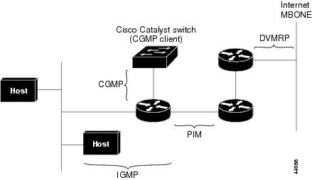
Figure 1. IP Multicast Routing Protocols. The following figure shows where the Cisco-supported protocols for the switch operate within the IP multicast environment.According to IPv4 multicast standards, the MAC destination multicast address begins with 0100:5e and is appended by the last 23 bits of the IP address. For example, if the IP destination address is 239.1.1.39, the MAC destination address is 0100:5e01:0127.
A multicast packet is unmatched when the destination IPv4 address does not match the destination MAC address. The switch forwards the unmatched packet in hardware based upon the MAC address table. If the destination MAC address is not in the MAC address table, the switch floods the packet to the all port in the same VLAN as the receiving port.
Related Tasks
Multicast Forwarding Information Base Overview
The switch uses the Multicast Forwarding Information Base (MFIB) architecture and the Multicast Routing Information Base (MRIB) for IP multicast.
The MFIB architecture provides both modularity and separation between the multicast control plane (Protocol Independent Multicast [PIM] and Internet Group Management Protocol [IGMP]) and the multicast forwarding plane (MFIB). This architecture is used in Cisco IOS IPv6 multicast implementations.
MFIB itself is a multicast routing protocol independent forwarding engine; that is, it does not depend on PIM or any other multicast routing protocol. It is responsible for:
- Forwarding multicast packets
- Registering with the MRIB to learn the entry and interface flags set by the control plane
- Handling data-driven events that must be sent to the control plane
- Maintaining counts, rates, and bytes of received, dropped, and forwarded multicast packets
The MRIB is the communication channel between MRIB clients. Examples of MRIB clients are PIM, IGMP, the multicast routing (mroute) table, and the MFIB.
Related Tasks
Multicast Group Concept
Multicast is based on the concept of a group. An arbitrary group of receivers expresses an interest in receiving a particular data stream. This group does not have any physical or geographical boundaries. The hosts can be located anywhere on the Internet. Hosts that are interested in receiving data flowing to a particular group must join the group using IGMP. Hosts must be a member of the group to receive the data stream.
Related Tasks
Related References
Multicast Boundaries
Administratively-scoped boundaries can be used to limit the forwarding of multicast traffic outside of a domain or subdomain. This approach uses a special range of multicast addresses, called administratively-scoped addresses, as the boundary mechanism. If you configure an administratively-scoped boundary on a routed interface, multicast traffic whose multicast group addresses fall in this range cannot enter or exit this interface, which provides a firewall for multicast traffic in this address range.
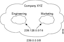
Figure 2. Administratively-Scoped Boundaries. The following figure shows that Company XYZ has an administratively-scoped boundary set for the multicast address range 239.0.0.0/8 on all routed interfaces at the perimeter of its network. This boundary prevents any multicast traffic in the range 239.0.0.0 through 239.255.255.255 from entering or leaving the network. Similarly, the engineering and marketing departments have an administratively-scoped boundary of 239.128.0.0/16 around the perimeter of their networks. This boundary prevents multicast traffic in the range of 239.128.0.0 through 239.128.255.255 from entering or leaving their respective networks.You can define an administratively-scoped boundary on a routed interface for multicast group addresses. A standard access list defines the range of addresses affected. When a boundary is defined, no multicast data packets are allowed to flow across the boundary from either direction. The boundary allows the same multicast group address to be reused in different administrative domains.
The IANA has designated the multicast address range 239.0.0.0 to 239.255.255.255 as the administratively-scoped addresses. This range of addresses can then be reused in domains administered by different organizations. The addresses would be considered local, not globally unique.
Related Tasks
Related References
Multicast Routing and Switch Stacks
For all multicast routing protocols, the entire stack appears as a single router to the network and operates as a single multicast router.
In a switch stack, the active switch performs these functions:
- It is responsible for completing the IP multicast routing functions of the stack. It fully initializes and runs the IP multicast routing protocols.
- It builds and maintains the multicast routing table for the entire stack.
- It is responsible for distributing the multicast routing table to all stack members.
The stack members perform these functions:
- They act as multicast routing standby devices and are ready to take over if there is a active switch failure. If the active switch fails, all stack members delete their multicast routing tables. The newly elected active switch starts building the routing tables and distributes them to the stack members.
- They do not build multicast routing tables. Instead, they use the multicast routing table that is distributed by the active switch.
How to Configure Basic IP Multicast Routing
- Configuring Basic IP Multicast Routing (CLI)
- Configuring IP Multicast Forwarding (CLI)
- Configuring a Static Multicast Route (mroute) (CLI)
- Configuring sdr Listener Support
- Configuring an IP Multicast Boundary (CLI)
Configuring Basic IP Multicast Routing (CLI)
SUMMARY STEPSYou must enable IP multicast routing and configure the PIM version and mode. After performing these tasks, the software can then forward multicast packets, and the switch can populate its multicast routing table.
You can configure an interface to be in PIM dense mode, sparse mode, or sparse-dense mode. The switch populates its multicast routing table and forwards multicast packets it receives from its directly connected LANs according to the mode setting. You must enable PIM in one of these modes for an interface to perform IP multicast routing.
Enabling PIM on an interface also enables IGMP operation on that interface.
In populating the multicast routing table, dense-mode interfaces are always added to the table. Sparse-mode interfaces are added to the table only when periodic join messages are received from downstream devices or when there is a directly connected member on the interface.
When forwarding from a LAN, sparse-mode operation occurs if there is a rendezvous point (RP) known for the group. An RP acts as the meeting place for sources and receivers of multicast data. If an RP exists, the packets are encapsulated and sent toward the RP. When no RP is known, the packet is flooded in a dense-mode fashion. If the multicast traffic from a specific source is sufficient, the receiver’s first-hop router might send join messages toward the source to build a source-based distribution tree.
By default, multicast routing is disabled, and there is no default mode setting.
DETAILED STEPS
Command or Action Purpose
Step 1 enable
Example:Switch> enableEnables privileged EXEC mode.
Step 2 configure terminal
Example:Switch# configure terminalStep 3 ip multicast-routing
Example:Switch(config)# ip multicast-routingEnables IP multicast routing.
IP multicast routing is supported with Multicast Forwarding Information Base (MFIB) and Multicast Routing Information Base (MRIB).
Step 4 interface interface-id
Example:Switch(config)# interface gigabitethernet 1/0/1Specifies the Layer 3 interface on which you want to enable multicast routing, and enters interface configuration mode.
The specified interface must be one of the following:
- A routed port—A physical port that has been configured as a Layer 3 port by entering the no switchport interface configuration command. You will also need to enable IP PIM sparse-dense-mode on the interface, and join the interface as a statically connected member to an IGMP static group. For a configuration example, see Example: Interface Configuration as a Routed Port
- An SVI—A VLAN interface created by using the interface vlan vlan-id global configuration command. You will also need to enable IP PIM sparse-dense-mode on the VLAN, join the VLAN as a statically connected member to an IGMP static group, and then enable IGMP snooping on the VLAN, the IGMP static group, and physical interface. For a configuration example, see Example: Interface Configuration as an SVI
Step 5 ip pim {dense-mode | sparse-mode | sparse-dense-mode}
Example:Switch(config-if)# ip pim sparse-dense-modeEnables a PIM mode on the interface.
By default, no mode is configured.
The keywords have these meanings:
- dense-mode—Enables dense mode of operation.
- sparse-mode—Enables sparse mode of operation. If you configure sparse mode, you must also configure an RP.
- sparse-dense-mode—Causes the interface to be treated in the mode in which the group belongs. Sparse-dense mode is the recommended setting.
- state-refresh—PM dense mode state-refresh configuration.
Step 6 end
Example:Switch(config-if)# endStep 7 show running-config
Example:Switch# show running-configStep 8 copy running-config startup-config
Example:Switch# copy running-config startup-config
Configuring IP Multicast Forwarding (CLI)
SUMMARY STEPSYou can use the following procedure to configure IPv4 Multicast Forwarding Information Base (MFIB) interrupt-level IP multicast forwarding of incoming packets or outgoing packets on the switch.
Note
After you have enabled IP multicast routing by using the ip multicast-routing command, IPv4 multicast forwarding is enabled. Because IPv4 multicast forwarding is enabled by default, you can use the no form of the ip mfib command to disable IPv4 multicast forwarding.
1. enable
3. ip mfib
DETAILED STEPSRelated Concepts
Configuring a Static Multicast Route (mroute) (CLI)
SUMMARY STEPSYou can use the following procedure to configure static mroutes. Static mroutes are similar to unicast static routes but differ in the following ways:
- Static mroutes are used to calculate RPF information, not to forward traffic.
- Static mroutes cannot be redistributed.
Static mroutes are strictly local to the switch on which they are defined. Because Protocol Independent Multicast (PIM) does not have its own routing protocol, there is no mechanism to distribute static mroutes throughout the network. Consequently, the administration of static mroutes tends to be more complicated than the administration of unicast static routes.
When static mroutes are configured, they are stored on the switch in a separate table referred to as the static mroute table. When configured, the ip mroute command enters a static mroute into the static mroute table for the source address or source address range specified for the source-address and mask arguments. Sources that match the source address or that fall in the source address range specified for the source-address argument will RPF to either the interface associated with the IP address specified for the rpf-address argument or the local interface on the switch specified for the interface-type and interface-number arguments. If an IP address is specified for the rpf-address argument, a recursive lookup is done from the unicast routing table on this address to find the directly connected neighbor.
If there are multiple static mroutes configured, the switch performs a longest-match lookup of the mroute table. When the mroute with the longest match (of the source-address) is found, the search terminates and the information in the matching static mroute is used. The order in which the static mroutes are configured is not important.
The administrative distance of an mroute may be specified for the optional distance argument. If a value is not specified for the distance argument, the distance of the mroute defaults to zero. If the static mroute has the same distance as another RPF source, the static mroute will take precedence. There are only two exceptions to this rule: directly connected routes and the default unicast route.
1. enable
3. ip mroute [vrf vrf-name] source-address mask { fallback-lookup {global | vrf vrf-name }[ protocol ] {rpf-address | interface-type interface-number}} [distance]
DETAILED STEPSConfiguring sdr Listener Support
The MBONE is the small subset of Internet routers and hosts that are interconnected and capable of forwarding IP multicast traffic. Other multimedia content is often broadcast over the MBONE. Before you can join a multimedia session, you need to know what multicast group address and port are being used for the session, when the session is going to be active, and what sort of applications (audio, video, and so forth) are required on your workstation. The MBONE Session Directory Version 2 (sdr) tool provides this information. This freeware application can be downloaded from several sites on the World Wide Web, one of which is http://www.video.ja.net/mice/index.html.
SDR is a multicast application that listens to a well-known multicast group address and port for Session Announcement Protocol (SAP) multicast packets from SAP clients, which announce their conference sessions. These SAP packets contain a session description, the time the session is active, its IP multicast group addresses, media format, contact person, and other information about the advertised multimedia session. The information in the SAP packet is displayed in the SDR Session Announcement window.
Enabling sdr Listener Support (CLI)
SUMMARY STEPS
1. enable
DETAILED STEPS
Command or Action Purpose
Step 1 enable
Example:Switch> enableEnables privileged EXEC mode.
Step 2 configure terminal
Example:Switch# configure terminalStep 3 interface interface-id
Example:Switch(config)# interface gigabitethernet 1/0/1Specifies the interface to be enabled for sdr, and enters interface configuration mode.
The specified interface must be one of the following:
- A routed port—A physical port that has been configured as a Layer 3 port by entering the no switchport interface configuration command. You will also need to enable IP PIM sparse-dense-mode on the interface, and join the interface as a statically connected member to an IGMP static group. For a configuration example, see Example: Interface Configuration as a Routed Port
- An SVI—A VLAN interface created by using the interface vlan vlan-id global configuration command. You will also need to enable IP PIM sparse-dense-mode on the VLAN, join the VLAN as a statically connected member to an IGMP static group, and then enable IGMP snooping on the VLAN, the IGMP static group, and physical interface. For a configuration example, see Example: Interface Configuration as an SVI
Step 4 ip sap listen
Example:Switch(config-if)# ip sap listenEnables the switch software to listen to session directory announcements.
Step 5 end
Example:Switch(config-if)# endStep 6 show running-config
Example:Switch# show running-configStep 7 copy running-config startup-config
Example:Switch# copy running-config startup-configLimiting How Long an sdr Cache Entry Exists (CLI)
SUMMARY STEPSBy default, entries are never deleted from the sdr cache. You can limit how long the entry remains active so that if a source stops advertising SAP information, old advertisements are not unnecessarily kept.
DETAILED STEPSConfiguring an IP Multicast Boundary (CLI)
SUMMARY STEPS
1. enable
3. access-list {access-list-number 1-99 | access-list-number 100-199 | access-list-number 1300-1999 |access-list-number 2000-2699 | dynamic-extended | rate-limit}
DETAILED STEPSWhat to Do Next
Command or Action Purpose
Step 1 enable
Example:Switch> enableEnables privileged EXEC mode.
Step 2 configure terminal
Example:Switch# configure terminalStep 3 access-list {access-list-number 1-99 | access-list-number 100-199 | access-list-number 1300-1999 |access-list-number 2000-2699 | dynamic-extended | rate-limit}
Example:Switch(config)# access-list 99 permit anyCreates a standard access list, repeating the command as many times as necessary.
- For access-list-number, the ranges are as follows:
- The dynamic-extended keyword extends the dynamic ACL absolute timer.
- The rate-limit keyword permits a simple rate-limit specific access list.
The access list is always terminated by an implicit deny statement for everything.
Step 4 interface interface-id
Example:Switch(config)# interface gigabitEthernet1/0/1Specifies the interface to be configured, and enters interface configuration mode.
The specified interface must be one of the following:
- A routed port—A physical port that has been configured as a Layer 3 port by entering the no switchport interface configuration command. You will also need to enable IP PIM sparse-dense-mode on the interface, and join the interface as a statically connected member to an IGMP static group. For a configuration example, see Example: Interface Configuration as a Routed Port
- An SVI—A VLAN interface created by using the interface vlan vlan-id global configuration command. You will also need to enable IP PIM sparse-dense-mode on the VLAN, join the VLAN as a statically connected member to an IGMP static group, and then enable IGMP snooping on the VLAN, the IGMP static group, and physical interface. For a configuration example, see Example: Interface Configuration as an SVI
Step 5 ip multicast boundary access-list-number
Example:Switch(config-if)# ip multicast boundary 99Configures the boundary, specifying the access list you created in Step 2.
Additional command options include:
Step 6 end
Example:Switch(config-if)# endStep 7 show running-config
Example:Switch# show running-configStep 8 copy running-config startup-config
Example:Switch# copy running-config startup-config
Proceed to the other supported IP multicast routing procedures.
Related References
Monitoring and Maintaining IP Multicast Routing
Clearing Caches, Tables, and Databases
You can remove all contents of a particular cache, table, or database. Clearing a cache, table, or database might be necessary when the contents of the particular structure are or suspected to be invalid.
Displaying System and Network Statistics
You can display specific statistics, such as the contents of IP routing tables, caches, and databases.
NoteThis release does not support per-route statistics.
You can display information to learn resource usage and solve network problems. You can also display information about node reachability and discover the routing path that packets of your device are taking through the network.
Monitoring IP Multicast Routing
Configuration Examples for IP Multicast Routing
Example: Responding to mrinfo Requests
The software answers mrinfo requests sent by mrouted systems and Cisco routers and multilayer switches. The software returns information about neighbors through DVMRP tunnels and all the routed interfaces. This information includes the metric (always set to 1), the configured TTL threshold, the status of the interface, and various flags. You can also use the mrinfo privileged EXEC command to query the router or switch itself, as in this example:
Switch# mrinfo 171.69.214.27 (mm1-7kd.cisco.com) [version cisco 11.1] [flags: PMS]: 171.69.214.27 -> 171.69.214.26 (mm1-r7kb.cisco.com) [1/0/pim/querier] 171.69.214.27 -> 171.69.214.25 (mm1-45a.cisco.com) [1/0/pim/querier] 171.69.214.33 -> 171.69.214.34 (mm1-45c.cisco.com) [1/0/pim] 171.69.214.137 -> 0.0.0.0 [1/0/pim/querier/down/leaf] 171.69.214.203 -> 0.0.0.0 [1/0/pim/querier/down/leaf] 171.69.214.18 -> 171.69.214.20 (mm1-45e.cisco.com) [1/0/pim] 171.69.214.18 -> 171.69.214.19 (mm1-45c.cisco.com) [1/0/pim] 171.69.214.18 -> 171.69.214.17 (mm1-45a.cisco.com) [1/0/pim]Additional References
Related Documents
Error Message Decoder
Description Link To help you research and resolve system error messages in this release, use the Error Message Decoder tool.
https://www.cisco.com/cgi-bin/Support/Errordecoder/index.cgi
MIBs
Technical Assistance
Description Link The Cisco Support website provides extensive online resources, including documentation and tools for troubleshooting and resolving technical issues with Cisco products and technologies.
To receive security and technical information about your products, you can subscribe to various services, such as the Product Alert Tool (accessed from Field Notices), the Cisco Technical Services Newsletter, and Really Simple Syndication (RSS) Feeds.
Access to most tools on the Cisco Support website requires a Cisco.com user ID and password.