Feedback
Contents
- Configuring Port-Based Traffic Control
- Overview of Port-Based Traffic Control
- Finding Feature Information
- Information About Storm Control
- Storm Control
- How Traffic Activity is Measured
- Traffic Patterns
- How to Configure Storm Control
- Configuring Storm Control and Threshold Levels
- Monitoring Storm Control
- Information About Protected Ports
- Protected Ports
- Default Protected Port Configuration
- Protected Ports Guidelines
- How to Configure Protected Ports
- Configuring a Protected Port
- Monitoring Protected Ports
- Information About Port Blocking
- Port Blocking
- How to Configure Port Blocking
- Blocking Flooded Traffic on an Interface
- Monitoring Port Blocking
- Prerequisites for Port Security
- Restrictions for Port Security
- Information About Port Security
- Port Security
- Types of Secure MAC Addresses
- Sticky Secure MAC Addresses
- Security Violations
- Port Security Aging
- Port Security and Switch Stacks
- Default Port Security Configuration
- Port Security Configuration Guidelines
- Overview of Port-Based Traffic Control
- How to Configure Port Security
- Enabling and Configuring Port Security
- Enabling and Configuring Port Security Aging
- Finding Feature Information
- Information About Storm Control
- Storm Control
- How Traffic Activity is Measured
- Traffic Patterns
- How to Configure Storm Control
- Configuring Storm Control and Threshold Levels
- Monitoring Storm Control
- Information About Protected Ports
- Protected Ports
- Default Protected Port Configuration
- Protected Ports Guidelines
- How to Configure Protected Ports
- Configuring a Protected Port
- Monitoring Protected Ports
- Information About Port Blocking
- Port Blocking
- How to Configure Port Blocking
- Blocking Flooded Traffic on an Interface
- Monitoring Port Blocking
- Configuration Examples for Port Security
Configuring Port-Based Traffic Control
Overview of Port-Based Traffic Control
Port-based traffic control is a set of Layer 2 features on the Cisco Catalyst switches used to filter or block packets at the port level in response to specific traffic conditions. The following port-based traffic control features are supported in the Cisco IOS Release for which this guide is written:
Finding Feature Information
Your software release may not support all the features documented in this module. For the latest feature information and caveats, see the release notes for your platform and software release.
Use Cisco Feature Navigator to find information about platform support and Cisco software image support. To access Cisco Feature Navigator, go to http://www.cisco.com/go/cfn. An account on Cisco.com is not required.
Information About Storm Control
Storm Control
Storm control prevents traffic on a LAN from being disrupted by a broadcast, multicast, or unicast storm on one of the physical interfaces. A LAN storm occurs when packets flood the LAN, creating excessive traffic and degrading network performance. Errors in the protocol-stack implementation, mistakes in network configurations, or users issuing a denial-of-service attack can cause a storm.
Storm control (or traffic suppression) monitors packets passing from an interface to the switching bus and determines if the packet is unicast, multicast, or broadcast. The switch counts the number of packets of a specified type received within the 1-second time interval and compares the measurement with a predefined suppression-level threshold.
How Traffic Activity is Measured
Storm control uses one of these methods to measure traffic activity:
- Bandwidth as a percentage of the total available bandwidth of the port that can be used by the broadcast, multicast, or unicast traffic
- Traffic rate in packets per second at which broadcast, multicast, or unicast packets are received
- Traffic rate in bits per second at which broadcast, multicast, or unicast packets are received
- Traffic rate in packets per second and for small frames. This feature is enabled globally. The threshold for small frames is configured for each interface.
With each method, the port blocks traffic when the rising threshold is reached. The port remains blocked until the traffic rate drops below the falling threshold (if one is specified) and then resumes normal forwarding. If the falling suppression level is not specified, the switch blocks all traffic until the traffic rate drops below the rising suppression level. In general, the higher the level, the less effective the protection against broadcast storms.
Traffic Patterns
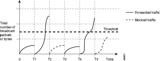
Figure 1. Broadcast Storm Control Example. This example shows broadcast traffic patterns on an interface over a given period of time.Broadcast traffic being forwarded exceeded the configured threshold between time intervals T1 and T2 and between T4 and T5. When the amount of specified traffic exceeds the threshold, all traffic of that kind is dropped for the next time period. Therefore, broadcast traffic is blocked during the intervals following T2 and T5. At the next time interval (for example, T3), if broadcast traffic does not exceed the threshold, it is again forwarded.
The combination of the storm-control suppression level and the 1-second time interval controls the way the storm control algorithm works. A higher threshold allows more packets to pass through. A threshold value of 100 percent means that no limit is placed on the traffic. A value of 0.0 means that all broadcast, multicast, or unicast traffic on that port is blocked.
NoteBecause packets do not arrive at uniform intervals, the 1-second time interval during which traffic activity is measured can affect the behavior of storm control.
You use the storm-control interface configuration commands to set the threshold value for each traffic type.
How to Configure Storm Control
Configuring Storm Control and Threshold Levels
You configure storm control on a port and enter the threshold level that you want to be used for a particular type of traffic.
However, because of hardware limitations and the way in which packets of different sizes are counted, threshold percentages are approximations. Depending on the sizes of the packets making up the incoming traffic, the actual enforced threshold might differ from the configured level by several percentage points.
Before You BeginSUMMARY STEPSStorm control is supported on physical interfaces. You can also configure storm control on an EtherChannel. When storm control is configured on an EtherChannel, the storm control settings propagate to the EtherChannel physical interfaces.
3. storm-control {broadcast | multicast | unicast} level {level [level-low] | bps bps [bps-low] | pps pps [pps-low]}
4. storm-control action {shutdown | trap}
6. show storm-control [interface-id] [broadcast | multicast | unicast]
DETAILED STEPSMonitoring Storm Control
Information About Protected Ports
Protected Ports
Some applications require that no traffic be forwarded at Layer 2 between ports on the same switch so that one neighbor does not see the traffic generated by another neighbor. In such an environment, the use of protected ports ensures that there is no exchange of unicast, broadcast, or multicast traffic between these ports on the switch.
Protected ports have these features:
- A protected port does not forward any traffic (unicast, multicast, or broadcast) to any other port that is also a protected port. Data traffic cannot be forwarded between protected ports at Layer 2; only control traffic, such as PIM packets, is forwarded because these packets are processed by the CPU and forwarded in software. All data traffic passing between protected ports must be forwarded through a Layer 3 device.
- Forwarding behavior between a protected port and a nonprotected port proceeds as usual.
Because a switch stack represents a single logical switch, Layer 2 traffic is not forwarded between any protected ports in the switch stack, whether they are on the same or different switches in the stack.
How to Configure Protected Ports
Configuring a Protected Port
SUMMARY STEPS
DETAILED STEPSInformation About Port Blocking
Port Blocking
By default, the switch floods packets with unknown destination MAC addresses out of all ports. If unknown unicast and multicast traffic is forwarded to a protected port, there could be security issues. To prevent unknown unicast or multicast traffic from being forwarded from one port to another, you can block a port (protected or nonprotected) from flooding unknown unicast or multicast packets to other ports.
NoteWith multicast traffic, the port blocking feature blocks only pure Layer 2 packets. Multicast packets that contain IPv4 or IPv6 information in the header are not blocked.
How to Configure Port Blocking
Blocking Flooded Traffic on an Interface
Before You BeginSUMMARY STEPSThe interface can be a physical interface or an EtherChannel group. When you block multicast or unicast traffic for a port channel, it is blocked on all ports in the port-channel group.
DETAILED STEPSRestrictions for Port Security
The maximum number of secure MAC addresses that you can configure on a switch or switch stack is set by the maximum number of available MAC addresses allowed in the system. This number is determined by the active Switch Database Management (SDM) template. This number is the total of available MAC addresses, including those used for other Layer 2 functions and any other secure MAC addresses configured on interfaces.
Information About Port Security
Port Security
You can use the port security feature to restrict input to an interface by limiting and identifying MAC addresses of the stations allowed to access the port. When you assign secure MAC addresses to a secure port, the port does not forward packets with source addresses outside the group of defined addresses. If you limit the number of secure MAC addresses to one and assign a single secure MAC address, the workstation attached to that port is assured the full bandwidth of the port.
If a port is configured as a secure port and the maximum number of secure MAC addresses is reached, when the MAC address of a station attempting to access the port is different from any of the identified secure MAC addresses, a security violation occurs. Also, if a station with a secure MAC address configured or learned on one secure port attempts to access another secure port, a violation is flagged.
Related Tasks
Related References
Types of Secure MAC Addresses
The switch supports these types of secure MAC addresses:
- Static secure MAC addresses—These are manually configured by using the switchport port-security mac-address mac-address interface configuration command, stored in the address table, and added to the switch running configuration.
- Dynamic secure MAC addresses—These are dynamically configured, stored only in the address table, and removed when the switch restarts.
- Sticky secure MAC addresses—These can be dynamically learned or manually configured, stored in the address table, and added to the running configuration. If these addresses are saved in the configuration file, when the switch restarts, the interface does not need to dynamically reconfigure them.
Sticky Secure MAC Addresses
You can configure an interface to convert the dynamic MAC addresses to sticky secure MAC addresses and to add them to the running configuration by enabling sticky learning. The interface converts all the dynamic secure MAC addresses, including those that were dynamically learned before sticky learning was enabled, to sticky secure MAC addresses. All sticky secure MAC addresses are added to the running configuration.
The sticky secure MAC addresses do not automatically become part of the configuration file, which is the startup configuration used each time the switch restarts. If you save the sticky secure MAC addresses in the configuration file, when the switch restarts, the interface does not need to relearn these addresses. If you do not save the sticky secure addresses, they are lost.
If sticky learning is disabled, the sticky secure MAC addresses are converted to dynamic secure addresses and are removed from the running configuration.
Security Violations
It is a security violation when one of these situations occurs:
- The maximum number of secure MAC addresses have been added to the address table, and a station whose MAC address is not in the address table attempts to access the interface.
- An address learned or configured on one secure interface is seen on another secure interface in the same VLAN.
You can configure the interface for one of three violation modes, based on the action to be taken if a violation occurs:
- protect—when the number of secure MAC addresses reaches the maximum limit allowed on the port, packets with unknown source addresses are dropped until you remove a sufficient number of secure MAC addresses to drop below the maximum value or increase the number of maximum allowable addresses. You are not notified that a security violation has occurred.
NoteWe do not recommend configuring the protect violation mode on a trunk port. The protect mode disables learning when any VLAN reaches its maximum limit, even if the port has not reached its maximum limit.
- restrict—when the number of secure MAC addresses reaches the maximum limit allowed on the port, packets with unknown source addresses are dropped until you remove a sufficient number of secure MAC addresses to drop below the maximum value or increase the number of maximum allowable addresses. In this mode, you are notified that a security violation has occurred. An SNMP trap is sent, a syslog message is logged, and the violation counter increments.
- shutdown—a port security violation causes the interface to become error-disabled and to shut down immediately, and the port LED turns off. When a secure port is in the error-disabled state, you can bring it out of this state by entering the errdisable recovery cause psecure-violation global configuration command, or you can manually re-enable it by entering the shutdown and no shut down interface configuration commands. This is the default mode.
- shutdown vlan—Use to set the security violation mode per-VLAN. In this mode, the VLAN is error disabled instead of the entire port when a violation occurs
This table shows the violation mode and the actions taken when you configure an interface for port security.
Table 4 Security Violation Mode Actions1 2 3 1 Packets with unknown source addresses are dropped until you remove a sufficient number of secure MAC addresses.2 The switch returns an error message if you manually configure an address that would cause a security violation.3 Shuts down only the VLAN on which the violation occurred.Port Security Aging
You can use port security aging to set the aging time for all secure addresses on a port. Two types of aging are supported per port:
Related Tasks
Port Security and Switch Stacks
When a switch joins a stack, the new switch will get the configured secure addresses. All dynamic secure addresses are downloaded by the new stack member from the other stack members.
When a switch (either the active switch or a stack member) leaves the stack, the remaining stack members are notified, and the secure MAC addresses configured or learned by that switch are deleted from the secure MAC address table.
Default Port Security Configuration
Port Security Configuration Guidelines
- Port security can only be configured on static access ports or trunk ports.
- A secure port cannot be a destination port for Switched Port Analyzer (SPAN).
- A secure port cannot belong to a Gigabit EtherChannel port group.
Note
Voice VLAN is only supported on access ports and not on trunk ports, even though the configuration is allowed.
- When you enable port security on an interface that is also configured with a voice VLAN, set the maximum allowed secure addresses on the port to two. When the port is connected to a Cisco IP phone, the IP phone requires one MAC address. The Cisco IP phone address is learned on the voice VLAN, but is not learned on the access VLAN. If you connect a single PC to the Cisco IP phone, no additional MAC addresses are required. If you connect more than one PC to the Cisco IP phone, you must configure enough secure addresses to allow one for each PC and one for the phone.
- When a trunk port configured with port security and assigned to an access VLAN for data traffic and to a voice VLAN for voice traffic, entering the switchport voice and switchport priority extend interface configuration commands has no effect. When a connected device uses the same MAC address to request an IP address for the access VLAN and then an IP address for the voice VLAN, only the access VLAN is assigned an IP address.
- When you enter a maximum secure address value for an interface, and the new value is greater than the previous value, the new value overwrites the previously configured value. If the new value is less than the previous value and the number of configured secure addresses on the interface exceeds the new value, the command is rejected.
- The switch does not support port security aging of sticky secure MAC addresses.
This table summarizes port security compatibility with other port-based features.
Table 6 Port Security Compatibility with Other Switch FeaturesVoice VLAN port 6
Overview of Port-Based Traffic Control
Port-based traffic control is a set of Layer 2 features on the Cisco Catalyst switches used to filter or block packets at the port level in response to specific traffic conditions. The following port-based traffic control features are supported in the Cisco IOS Release for which this guide is written:
How to Configure Port Security
- Enabling and Configuring Port Security
- Enabling and Configuring Port Security Aging
- Finding Feature Information
- Information About Storm Control
- How to Configure Storm Control
- Monitoring Storm Control
- Information About Protected Ports
- How to Configure Protected Ports
- Monitoring Protected Ports
- Information About Port Blocking
- How to Configure Port Blocking
- Monitoring Port Blocking
Enabling and Configuring Port Security
Before You BeginSUMMARY STEPSThis task restricts input to an interface by limiting and identifying MAC addresses of the stations allowed to access the port:
3. switchport mode {access | trunk}
4. switchport voice vlan vlan-id
6. switchport port-security [maximum value [vlan {vlan-list | {access | voice}}]]
7. switchport port-security violation {protect | restrict | shutdown | shutdown vlan}
8. switchport port-security [mac-address mac-address [vlan {vlan-id | {access | voice}}]
9. switchport port-security mac-address sticky
10. switchport port-security mac-address sticky [mac-address | vlan {vlan-id | {access | voice}}]
DETAILED STEPS
Command or Action Purpose
Step 1 configure terminal
Example:Switch# configure terminalStep 2 interface interface-id
Example:Switch(config)# interface gigabitethernet1/0/1Specifies the interface to be configured, and enter interface configuration mode.
Step 3 switchport mode {access | trunk}
Example:Switch(config-if)# switchport mode accessSets the interface switchport mode as access or trunk; an interface in the default mode (dynamic auto) cannot be configured as a secure port.
Step 4 switchport voice vlan vlan-id
Example:Switch(config-if)# switchport voice vlan 22Step 5 switchport port-security
Example:Switch(config-if)# switchport port-securityStep 6 switchport port-security [maximum value [vlan {vlan-list | {access | voice}}]]
Example:Switch(config-if)# switchport port-security maximum 20(Optional) Sets the maximum number of secure MAC addresses for the interface. The maximum number of secure MAC addresses that you can configure on a switch or switch stack is set by the maximum number of available MAC addresses allowed in the system. This number is set by the active Switch Database Management (SDM) template. This number is the total of available MAC addresses, including those used for other Layer 2 functions and any other secure MAC addresses configured on interfaces.
(Optional) vlan—sets a per-VLAN maximum value
Enter one of these options after you enter the vlan keyword:
- vlan-list—On a trunk port, you can set a per-VLAN maximum value on a range of VLANs separated by a hyphen or a series of VLANs separated by commas. For nonspecified VLANs, the per-VLAN maximum value is used.
- access—On an access port, specifies the VLAN as an access VLAN.
- voice—On an access port, specifies the VLAN as a voice VLAN.
Note The voice keyword is available only if a voice VLAN is configured on a port and if that port is not the access VLAN. If an interface is configured for voice VLAN, configure a maximum of two secure MAC addresses.
Step 7 switchport port-security violation {protect | restrict | shutdown | shutdown vlan}
Example:Switch(config-if)# switchport port-security violation restrict(Optional) Sets the violation mode, the action to be taken when a security violation is detected, as one of these:
- protect—When the number of port secure MAC addresses reaches the maximum limit allowed on the port, packets with unknown source addresses are dropped until you remove a sufficient number of secure MAC addresses to drop below the maximum value or increase the number of maximum allowable addresses. You are not notified that a security violation has occurred.
Note We do not recommend configuring the protect mode on a trunk port. The protect mode disables learning when any VLAN reaches its maximum limit, even if the port has not reached its maximum limit.
- restrict—When the number of secure MAC addresses reaches the limit allowed on the port, packets with unknown source addresses are dropped until you remove a sufficient number of secure MAC addresses or increase the number of maximum allowable addresses. An SNMP trap is sent, a syslog message is logged, and the violation counter increments.
- shutdown—The interface is error-disabled when a violation occurs, and the port LED turns off. An SNMP trap is sent, a syslog message is logged, and the violation counter increments.
Note When a secure port is in the error-disabled state, you can bring it out of this state by entering the errdisable recovery cause psecure-violation global configuration command. You can manually re-enable it by entering the shutdown and no shutdown interface configuration commands or by using the clear errdisable interface vlan privileged EXEC command.
Step 8 switchport port-security [mac-address mac-address [vlan {vlan-id | {access | voice}}]
Example:Switch(config-if)# switchport port-security mac-address 00:A0:C7:12:C9:25 vlan 3 voice(Optional) Enters a secure MAC address for the interface. You can use this command to enter the maximum number of secure MAC addresses. If you configure fewer secure MAC addresses than the maximum, the remaining MAC addresses are dynamically learned.
Note If you enable sticky learning after you enter this command, the secure addresses that were dynamically learned are converted to sticky secure MAC addresses and are added to the running configuration.
(Optional) vlan—sets a per-VLAN maximum value.
Enter one of these options after you enter the vlan keyword:
- vlan-id—On a trunk port, you can specify the VLAN ID and the MAC address. If you do not specify a VLAN ID, the native VLAN is used.
- access—On an access port, specifies the VLAN as an access VLAN.
- voice—On an access port, specifies the VLAN as a voice VLAN.
Note The voice keyword is available only if a voice VLAN is configured on a port and if that port is not the access VLAN. If an interface is configured for voice VLAN, configure a maximum of two secure MAC addresses.
Step 9 switchport port-security mac-address sticky
Example:Switch(config-if)# switchport port-security mac-address stickyStep 10 switchport port-security mac-address sticky [mac-address | vlan {vlan-id | {access | voice}}]
Example:Switch(config-if)# switchport port-security mac-address sticky 00:A0:C7:12:C9:25 vlan voice(Optional) Enters a sticky secure MAC address, repeating the command as many times as necessary. If you configure fewer secure MAC addresses than the maximum, the remaining MAC addresses are dynamically learned, are converted to sticky secure MAC addresses, and are added to the running configuration.
Note If you do not enable sticky learning before this command is entered, an error message appears, and you cannot enter a sticky secure MAC address.
(Optional) vlan—sets a per-VLAN maximum value.
Enter one of these options after you enter the vlan keyword:
- vlan-id—On a trunk port, you can specify the VLAN ID and the MAC address. If you do not specify a VLAN ID, the native VLAN is used.
- access—On an access port, specifies the VLAN as an access VLAN.
- voice—On an access port, specifies the VLAN as a voice VLAN.
Note The voice keyword is available only if a voice VLAN is configured on a port and if that port is not the access VLAN.
Step 11 end
Example:Switch(config-if)# endStep 12 show port-security
Example:Switch# show port-securityStep 13 copy running-config startup-config
Example:Switch# copy running-config startup-config
Related References
Enabling and Configuring Port Security Aging
SUMMARY STEPSUse this feature to remove and add devices on a secure port without manually deleting the existing secure MAC addresses and to still limit the number of secure addresses on a port. You can enable or disable the aging of secure addresses on a per-port basis.
3. switchport port-security aging {static | time time | type {absolute | inactivity}}
DETAILED STEPS
Command or Action Purpose
Step 1 configure terminal
Example:Switch# configure terminalStep 2 interface interface-id
Example:Switch(config)# interface gigabitethernet1/0/1Specifies the interface to be configured, and enter interface configuration mode.
Step 3 switchport port-security aging {static | time time | type {absolute | inactivity}}
Example:Switch(config-if)# switchport port-security aging time 120Enables or disable static aging for the secure port, or set the aging time or type.
Note The switch does not support port security aging of sticky secure addresses.
Enter static to enable aging for statically configured secure addresses on this port.
For time, specifies the aging time for this port. The valid range is from 0 to 1440 minutes.
For type, select one of these keywords:
- absolute—Sets the aging type as absolute aging. All the secure addresses on this port age out exactly after the time (minutes) specified lapses and are removed from the secure address list.
- inactivity—Sets the aging type as inactivity aging. The secure addresses on this port age out only if there is no data traffic from the secure source addresses for the specified time period.
Step 4 end
Example:Switch(config)# endStep 5 show port-security [interface interface-id] [address]
Example:Switch# show port-security interface gigabitethernet1/0/1Step 6 copy running-config startup-config
Example:Switch# copy running-config startup-config
Finding Feature Information
Your software release may not support all the features documented in this module. For the latest feature information and caveats, see the release notes for your platform and software release.
Use Cisco Feature Navigator to find information about platform support and Cisco software image support. To access Cisco Feature Navigator, go to http://www.cisco.com/go/cfn. An account on Cisco.com is not required.
Information About Storm Control
Storm Control
Storm control prevents traffic on a LAN from being disrupted by a broadcast, multicast, or unicast storm on one of the physical interfaces. A LAN storm occurs when packets flood the LAN, creating excessive traffic and degrading network performance. Errors in the protocol-stack implementation, mistakes in network configurations, or users issuing a denial-of-service attack can cause a storm.
Storm control (or traffic suppression) monitors packets passing from an interface to the switching bus and determines if the packet is unicast, multicast, or broadcast. The switch counts the number of packets of a specified type received within the 1-second time interval and compares the measurement with a predefined suppression-level threshold.
How Traffic Activity is Measured
Storm control uses one of these methods to measure traffic activity:
- Bandwidth as a percentage of the total available bandwidth of the port that can be used by the broadcast, multicast, or unicast traffic
- Traffic rate in packets per second at which broadcast, multicast, or unicast packets are received
- Traffic rate in bits per second at which broadcast, multicast, or unicast packets are received
- Traffic rate in packets per second and for small frames. This feature is enabled globally. The threshold for small frames is configured for each interface.
With each method, the port blocks traffic when the rising threshold is reached. The port remains blocked until the traffic rate drops below the falling threshold (if one is specified) and then resumes normal forwarding. If the falling suppression level is not specified, the switch blocks all traffic until the traffic rate drops below the rising suppression level. In general, the higher the level, the less effective the protection against broadcast storms.
NoteWhen the storm control threshold for multicast traffic is reached, all multicast traffic except control traffic, such as bridge protocol data unit (BDPU) and Cisco Discovery Protocol (CDP) frames, are blocked. However, the switch does not differentiate between routing updates, such as OSPF, and regular multicast data traffic, so both types of traffic are blocked.
Traffic Patterns
Figure 2. Broadcast Storm Control Example. This example shows broadcast traffic patterns on an interface over a given period of time.Broadcast traffic being forwarded exceeded the configured threshold between time intervals T1 and T2 and between T4 and T5. When the amount of specified traffic exceeds the threshold, all traffic of that kind is dropped for the next time period. Therefore, broadcast traffic is blocked during the intervals following T2 and T5. At the next time interval (for example, T3), if broadcast traffic does not exceed the threshold, it is again forwarded.
The combination of the storm-control suppression level and the 1-second time interval controls the way the storm control algorithm works. A higher threshold allows more packets to pass through. A threshold value of 100 percent means that no limit is placed on the traffic. A value of 0.0 means that all broadcast, multicast, or unicast traffic on that port is blocked.
NoteBecause packets do not arrive at uniform intervals, the 1-second time interval during which traffic activity is measured can affect the behavior of storm control.
You use the storm-control interface configuration commands to set the threshold value for each traffic type.
How to Configure Storm Control
Configuring Storm Control and Threshold Levels
You configure storm control on a port and enter the threshold level that you want to be used for a particular type of traffic.
However, because of hardware limitations and the way in which packets of different sizes are counted, threshold percentages are approximations. Depending on the sizes of the packets making up the incoming traffic, the actual enforced threshold might differ from the configured level by several percentage points.
Before You BeginSUMMARY STEPSStorm control is supported on physical interfaces. You can also configure storm control on an EtherChannel. When storm control is configured on an EtherChannel, the storm control settings propagate to the EtherChannel physical interfaces.
3. storm-control {broadcast | multicast | unicast} level {level [level-low] | bps bps [bps-low] | pps pps [pps-low]}
4. storm-control action {shutdown | trap}
6. show storm-control [interface-id] [broadcast | multicast | unicast]
DETAILED STEPS
Command or Action Purpose
Step 1 configure terminal
Example:Switch# configure terminalStep 2 interface interface-id
Example:Switch(config)# interface gigabitethernet1/0/1Specifies the interface to be configured, and enter interface configuration mode.
Step 3 storm-control {broadcast | multicast | unicast} level {level [level-low] | bps bps [bps-low] | pps pps [pps-low]}
Example:Switch(config-if)# storm-control unicast level 87 65Configures broadcast, multicast, or unicast storm control. By default, storm control is disabled.
The keywords have these meanings:
- For level, specifies the rising threshold level for broadcast, multicast, or unicast traffic as a percentage (up to two decimal places) of the bandwidth. The port blocks traffic when the rising threshold is reached. The range is 0.00 to 100.00.
- (Optional) For level-low, specifies the falling threshold level as a percentage (up to two decimal places) of the bandwidth. This value must be less than or equal to the rising suppression value. The port forwards traffic when traffic drops below this level. If you do not configure a falling suppression level, it is set to the rising suppression level. The range is 0.00 to 100.00. If you set the threshold to the maximum value (100 percent), no limit is placed on the traffic. If you set the threshold to 0.0, all broadcast, multicast, and unicast traffic on that port is blocked.
- For bps bps, specifies the rising threshold level for broadcast, multicast, or unicast traffic in bits per second (up to one decimal place). The port blocks traffic when the rising threshold is reached. The range is 0.0 to 10000000000.0.
- (Optional) For bps-low, specifies the falling threshold level in bits per second (up to one decimal place). It can be less than or equal to the rising threshold level. The port forwards traffic when traffic drops below this level. The range is 0.0 to 10000000000.0.
- For pps pps, specifies the rising threshold level for broadcast, multicast, or unicast traffic in packets per second (up to one decimal place). The port blocks traffic when the rising threshold is reached. The range is 0.0 to 10000000000.0.
- (Optional) For pps-low, specifies the falling threshold level in packets per second (up to one decimal place). It can be less than or equal to the rising threshold level. The port forwards traffic when traffic drops below this level. The range is 0.0 to 10000000000.0.
For BPS and PPS settings, you can use metric suffixes such as k, m, and g for large number thresholds.
Step 4 storm-control action {shutdown | trap}
Example:Switch(config-if)# storm-control action trapSpecifies the action to be taken when a storm is detected. The default is to filter out the traffic and not to send traps.
Step 5 end
Example:Switch(config-if)# endStep 6 show storm-control [interface-id] [broadcast | multicast | unicast]
Example:Switch# show storm-control gigabitethernet1/0/1 unicastVerifies the storm control suppression levels set on the interface for the specified traffic type. If you do not enter a traffic type, broadcast storm control settings are displayed.
Step 7 copy running-config startup-config
Example:Switch# copy running-config startup-configMonitoring Storm Control
Table 7 Commands for Displaying Storm Control Status and Configuration Command
Purpose
Displays the administrative and operational status of all switching (nonrouting) ports or the specified port, including port blocking and port protection settings.
show storm-control [interface-id] [broadcast | multicast | unicast]
Displays storm control suppression levels set on all interfaces or the specified interface for the specified traffic type or for broadcast traffic if no traffic type is entered.
Information About Protected Ports
Protected Ports
Some applications require that no traffic be forwarded at Layer 2 between ports on the same switch so that one neighbor does not see the traffic generated by another neighbor. In such an environment, the use of protected ports ensures that there is no exchange of unicast, broadcast, or multicast traffic between these ports on the switch.
Protected ports have these features:
- A protected port does not forward any traffic (unicast, multicast, or broadcast) to any other port that is also a protected port. Data traffic cannot be forwarded between protected ports at Layer 2; only control traffic, such as PIM packets, is forwarded because these packets are processed by the CPU and forwarded in software. All data traffic passing between protected ports must be forwarded through a Layer 3 device.
- Forwarding behavior between a protected port and a nonprotected port proceeds as usual.
Because a switch stack represents a single logical switch, Layer 2 traffic is not forwarded between any protected ports in the switch stack, whether they are on the same or different switches in the stack.
How to Configure Protected Ports
Configuring a Protected Port
SUMMARY STEPS
DETAILED STEPS
Command or Action Purpose
Step 1 configure terminal
Example:Switch# configure terminalStep 2 interface interface-id
Example:Switch(config)# interface gigabitethernet1/0/1Specifies the interface to be configured, and enter interface configuration mode.
Step 3 switchport protected
Example:Switch(config-if)# switchport protectedStep 4 end
Example:Switch(config-if)# endStep 5 show interfaces interface-id switchport
Example:Switch# show interfaces gigabitethernet1/0/1 switchportStep 6 copy running-config startup-config
Example:Switch# copy running-config startup-configInformation About Port Blocking
Port Blocking
By default, the switch floods packets with unknown destination MAC addresses out of all ports. If unknown unicast and multicast traffic is forwarded to a protected port, there could be security issues. To prevent unknown unicast or multicast traffic from being forwarded from one port to another, you can block a port (protected or nonprotected) from flooding unknown unicast or multicast packets to other ports.
NoteWith multicast traffic, the port blocking feature blocks only pure Layer 2 packets. Multicast packets that contain IPv4 or IPv6 information in the header are not blocked.
How to Configure Port Blocking
Blocking Flooded Traffic on an Interface
Before You BeginSUMMARY STEPSThe interface can be a physical interface or an EtherChannel group. When you block multicast or unicast traffic for a port channel, it is blocked on all ports in the port-channel group.
DETAILED STEPS
Command or Action Purpose
Step 1 configure terminal
Example:Switch# configure terminalStep 2 interface interface-id
Example:Switch(config)# interface gigabitethernet1/0/1Specifies the interface to be configured, and enter interface configuration mode.
Step 3 switchport block multicast
Example:Switch(config-if)# switchport block multicastBlocks unknown multicast forwarding out of the port.
Note Only pure Layer 2 multicast traffic is blocked. Multicast packets that contain IPv4 or IPv6 information in the header are not blocked.
Step 4 switchport block unicast
Example:Switch(config-if)# switchport block unicastStep 5 end
Example:Switch(config-if)# endStep 6 show interfaces interface-id switchport
Example:Switch# show interfaces gigabitethernet1/0/1 switchportStep 7 copy running-config startup-config
Example:Switch# copy running-config startup-configConfiguration Examples for Port Security
This example shows how to enable port security on a port and to set the maximum number of secure addresses to 50. The violation mode is the default, no static secure MAC addresses are configured, and sticky learning is enabled.
Switch(config)# interface gigabitethernet1/0/1
Switch(config-if)# switchport mode access
Switch(config-if)# switchport port-security
Switch(config-if)# switchport port-security maximum 50
Switch(config-if)# switchport port-security mac-address sticky
This example shows how to configure a static secure MAC address on VLAN 3 on a port:
Switch(config)# interface gigabitethernet1/0/2
Switch(config-if)# switchport mode trunk
Switch(config-if)# switchport port-security
Switch(config-if)# switchport port-security mac-address 0000.0200.0004 vlan 3
This example shows how to enable sticky port security on a port, to manually configure MAC addresses for data VLAN and voice VLAN, and to set the total maximum number of secure addresses to 20 (10 for data VLAN and 10 for voice VLAN).
Switch(config)# interface tengigabitethernet1/0/1
Switch(config-if)# switchport access vlan 21
Switch(config-if)# switchport mode access
Switch(config-if)# switchport voice vlan 22
Switch(config-if)# switchport port-security
Switch(config-if)# switchport port-security maximum 20
Switch(config-if)# switchport port-security violation restrict
Switch(config-if)# switchport port-security mac-address sticky
Switch(config-if)# switchport port-security mac-address sticky 0000.0000.0002
Switch(config-if)# switchport port-security mac-address 0000.0000.0003
Switch(config-if)# switchport port-security mac-address sticky 0000.0000.0001 vlan voice
Switch(config-if)# switchport port-security mac-address 0000.0000.0004 vlan voice
Switch(config-if)# switchport port-security maximum 10 vlan access
Switch(config-if)# switchport port-security maximum 10 vlan voice
Related Concepts
Related Tasks