Configuring VLAN Trunks

Contents

Configuring VLAN Trunks

Finding Feature Information

Your software release may not support all the features documented in this module. For the latest feature information and caveats, see the release notes for your platform and software release.

Use Cisco Feature Navigator to find information about platform support and Cisco software image support. To access Cisco Feature Navigator, go to http:/​/​www.cisco.com/​go/​cfn. An account on Cisco.com is not required.

Prerequisites for VLAN Trunks

The IEEE 802.1Q trunks impose these limitations on the trunking strategy for a network:

  • In a network of Cisco switches connected through IEEE 802.1Q trunks, the switches maintain one spanning-tree instance for each VLAN allowed on the trunks. Non-Cisco devices might support one spanning-tree instance for all VLANs. When you connect a Cisco switch to a non-Cisco device through an IEEE 802.1Q trunk, the Cisco switch combines the spanning-tree instance of the VLAN of the trunk with the spanning-tree instance of the non-Cisco IEEE 802.1Q switch. However, spanning-tree information for each VLAN is maintained by Cisco switches separated by a cloud of non-Cisco IEEE 802.1Q switches. The non-Cisco IEEE 802.1Q cloud separating the Cisco switches is treated as a single trunk link between the switches.
  • Make sure the native VLAN for an IEEE 802.1Q trunk is the same on both ends of the trunk link. If the native VLAN on one end of the trunk is different from the native VLAN on the other end, spanning-tree loops might result.
  • Disabling spanning tree on the native VLAN of an IEEE 802.1Q trunk without disabling spanning tree on every VLAN in the network can potentially cause spanning-tree loops. We recommend that you leave spanning tree enabled on the native VLAN of an IEEE 802.1Q trunk or disable spanning tree on every VLAN in the network. Make sure your network is loop-free before disabling spanning tree.

Restrictions for VLAN Trunks

Dynamic Trunking Protocol (DTP) is not supported on private-VLAN ports or tunnel ports.

The switch does not support Layer 3 trunks; you cannot configure subinterfaces or use the encapsulation keyword on Layer 3 interfaces. The switch does support Layer 2 trunks and Layer 3 VLAN interfaces, which provide equivalent capabilities.

Information About VLAN Trunks

Trunking Overview

A trunk is a point-to-point link between one or more Ethernet switch interfaces and another networking device such as a router or a switch. Ethernet trunks carry the traffic of multiple VLANs over a single link, and you can extend the VLANs across an entire network.

The following trunking encapsulations are available on all Ethernet interfaces:

  • Inter-Switch Link (ISL)—Cisco-proprietary trunking encapsulation.
  • IEEE 802.1Q— industry-standard trunking encapsulation.
Figure 1. Switches in an ISL Trunking Environment. You can configure a trunk on a single Ethernet interface or on an EtherChannel bundle.


Trunking Modes

Ethernet trunk interfaces support different trunking modes. You can set an interface as trunking or nontrunking or to negotiate trunking with the neighboring interface. To autonegotiate trunking, the interfaces must be in the same VTP domain.

Trunk negotiation is managed by the Dynamic Trunking Protocol (DTP), which is a Point-to-Point Protocol (PPP). However, some internetworking devices might forward DTP frames improperly, which could cause misconfigurations.

Related References

Layer 2 Interface Modes

Table 1 Layer 2 Interface Modes

Mode

Function

switchport mode access

Puts the interface (access port) into permanent nontrunking mode and negotiates to convert the link into a nontrunk link. The interface becomes a nontrunk interface regardless of whether or not the neighboring interface is a trunk interface.

switchport mode dynamic auto

Makes the interface able to convert the link to a trunk link. The interface becomes a trunk interface if the neighboring interface is set to trunk or desirable mode. The default switchport mode for all Ethernet interfaces is dynamic auto.

switchport mode dynamic desirable

Makes the interface actively attempt to convert the link to a trunk link. The interface becomes a trunk interface if the neighboring interface is set to trunk, desirable, or auto mode.

switchport mode trunk

Puts the interface into permanent trunking mode and negotiates to convert the neighboring link into a trunk link. The interface becomes a trunk interface even if the neighboring interface is not a trunk interface.

switchport nonegotiate

Prevents the interface from generating DTP frames. You can use this command only when the interface switchport mode is access or trunk. You must manually configure the neighboring interface as a trunk interface to establish a trunk link.

switchport mode dot1q-tunnel

Configures the interface as a tunnel (nontrunking) port to be connected in an asymmetric link with an IEEE 802.1Q trunk port. The IEEE 802.1Q tunneling is used to maintain customer VLAN integrity across a service provider network.

Related Concepts

Ethernet Trunk Encapsulation Types

This table lists the Ethernet trunk encapsulation types and keywords.

Table 2 Ethernet Trunk Encapsulation Types and Keywords

Encapsulation

Function

switchport trunk encapsulation isl

Specifies ISL encapsulation on the trunk link.

switchport trunk encapsulation dot1q

Specifies IEEE 802.1Q encapsulation on the trunk link.

switchport trunk encapsulation negotiate

Specifies that the interface negotiate with the neighboring interface to become an ISL (preferred) or IEEE 802.1Q trunk, depending on the configuration and capabilities of the neighboring interface. This is the default for the switch.

This table lists the Ethernet trunk encapsulation types and keywords.

Table 3 Ethernet Trunk Encapsulation Types and Keywords

Encapsulation

Function

switchport trunk encapsulation dot1q

Specifies IEEE 802.1Q encapsulation on the trunk link.

switchport trunk encapsulation negotiate

Specifies that the interface negotiate with the neighboring interface to become an ISL (preferred) or IEEE 802.1Q trunk, depending on the configuration and capabilities of the neighboring interface. This is the default for the switch.

The trunking mode, the trunk encapsulation type, and the hardware capabilities of the two connected interfaces decide whether a link becomes an ISL or IEEE 802.1Q trunk.

Allowed VLANs on a Trunk

By default, a trunk port sends traffic to and receives traffic from all VLANs. All VLAN IDs, 1 to 4094, are allowed on each trunk. However, you can remove VLANs from the allowed list, preventing traffic from those VLANs from passing over the trunk.

To reduce the risk of spanning-tree loops or storms, you can disable VLAN 1 on any individual VLAN trunk port by removing VLAN 1 from the allowed list. When you remove VLAN 1 from a trunk port, the interface continues to send and receive management traffic, for example, Cisco Discovery Protocol (CDP), Port Aggregation Protocol (PAgP), Link Aggregation Control Protocol (LACP), DTP, and VTP in VLAN 1.

If a trunk port with VLAN 1 disabled is converted to a nontrunk port, it is added to the access VLAN. If the access VLAN is set to 1, the port will be added to VLAN 1, regardless of the switchport trunk allowed setting. The same is true for any VLAN that has been disabled on the port.

A trunk port can become a member of a VLAN if the VLAN is enabled, if VTP knows of the VLAN, and if the VLAN is in the allowed list for the port. When VTP detects a newly enabled VLAN and the VLAN is in the allowed list for a trunk port, the trunk port automatically becomes a member of the enabled VLAN. When VTP detects a new VLAN and the VLAN is not in the allowed list for a trunk port, the trunk port does not become a member of the new VLAN.

Load Sharing on Trunk Ports

Load sharing divides the bandwidth supplied by parallel trunks connecting switches. To avoid loops, STP normally blocks all but one parallel link between switches. Using load sharing, you divide the traffic between the links according to which VLAN the traffic belongs.

You configure load sharing on trunk ports by using STP port priorities or STP path costs. For load sharing using STP port priorities, both load-sharing links must be connected to the same switch. For load sharing using STP path costs, each load-sharing link can be connected to the same switch or to two different switches.

Network Load Sharing Using STP Priorities

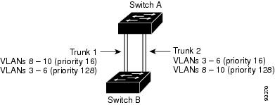
When two ports on the same switch form a loop, the switch uses the STP port priority to decide which port is enabled and which port is in a blocking state. You can set the priorities on a parallel trunk port so that the port carries all the traffic for a given VLAN. The trunk port with the higher priority (lower values) for a VLAN is forwarding traffic for that VLAN. The trunk port with the lower priority (higher values) for the same VLAN remains in a blocking state for that VLAN. One trunk port sends or receives all traffic for the VLAN.

Figure 2. Load Sharing by Using STP Port Priorities.

This figure shows two trunks connecting supported switches.

  • VLANs 8 through 10 are assigned a port priority of 16 on Trunk 1.
  • VLANs 3 through 6 retain the default port priority of 128 on Trunk 1.
  • VLANs 3 through 6 are assigned a port priority of 16 on Trunk 2.
  • VLANs 8 through 10 retain the default port priority of 128 on Trunk 2.


Trunk 1 carries traffic for VLANs 8 through 10, and Trunk 2 carries traffic for VLANs 3 through 6. If the active trunk fails, the trunk with the lower priority takes over and carries the traffic for all of the VLANs. No duplication of traffic occurs over any trunk port.

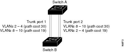
Network Load Sharing Using STP Path Cost

You can configure parallel trunks to share VLAN traffic by setting different path costs on a trunk and associating the path costs with different sets of VLANs, blocking different ports for different VLANs. The VLANs keep the traffic separate and maintain redundancy in the event of a lost link.

Figure 3. Load-Sharing Trunks with Traffic Distributed by Path Cost.

Trunk ports 1 and 2 are configured as 100BASE-T ports. These VLAN path costs are assigned:

  • VLANs 2 through 4 are assigned a path cost of 30 on Trunk port 1.
  • VLANs 8 through 10 retain the default 100BASE-T path cost on Trunk port 1 of 19.
  • VLANs 8 through 10 are assigned a path cost of 30 on Trunk port 2.
  • VLANs 2 through 4 retain the default 100BASE-T path cost on Trunk port 2 of 19.


Feature Interactions

Trunking interacts with other features in these ways:

  • A trunk port cannot be a secure port.
  • A trunk port cannot be a tunnel port.
  • Trunk ports can be grouped into EtherChannel port groups, but all trunks in the group must have the same configuration. When a group is first created, all ports follow the parameters set for the first port to be added to the group. If you change the configuration of one of these parameters, the switch propagates the setting that you entered to all ports in the group:
    • Allowed-VLAN list.
    • STP port priority for each VLAN.
    • STP Port Fast setting.
    • Trunk status: If one port in a port group ceases to be a trunk, all ports cease to be trunks.
  • We recommend that you configure no more than 24 trunk ports in Per VLAN Spanning Tree (PVST) mode and no more than 40 trunk ports in Multiple Spanning Tree (MST) mode.
  • If you try to enable IEEE 802.1x on a trunk port, an error message appears, and IEEE 802.1x is not enabled. If you try to change the mode of an IEEE 802.1x-enabled port to trunk, the port mode is not changed.
  • A port in dynamic mode can negotiate with its neighbor to become a trunk port. If you try to enable IEEE 802.1x on a dynamic port, an error message appears, and IEEE 802.1x is not enabled. If you try to change the mode of an IEEE 802.1x-enabled port to dynamic, the port mode is not changed.

How to Configure VLAN Trunks

To avoid trunking misconfigurations, configure interfaces connected to devices that do not support DTP to not forward DTP frames, that is, to turn off DTP.

  • If you do not intend to trunk across those links, use the switchport mode access interface configuration command to disable trunking.
  • To enable trunking to a device that does not support DTP, use the switchport mode trunk and switchport nonegotiate interface configuration commands to cause the interface to become a trunk but to not generate DTP frames.

Configuring an Ethernet Interface as a Trunk Port

Configuring a Trunk Port

Because trunk ports send and receive VTP advertisements, to use VTP you must ensure that at least one trunk port is configured on the switch and that this trunk port is connected to the trunk port of a second switch. Otherwise, the switch cannot receive any VTP advertisements.

Before You Begin

By default, an interface is in Layer 2 mode. The default mode for Layer 2 interfaces is switchport mode dynamic auto. If the neighboring interface supports trunking and is configured to allow trunking, the link is a Layer 2 trunk or, if the interface is in Layer 3 mode, it becomes a Layer 2 trunk when you enter the switchport interface configuration command.

SUMMARY STEPS

    1.    configure terminal

    2.    interface interface-id

    3.    switchport mode {dynamic {auto | desirable} | trunk}

    4.    switchport access vlan vlan-id

    5.    switchport trunk native vlan vlan-id

    6.    end

    7.    show interfaces interface-id switchport

    8.    show interfaces interface-id trunk

    9.    copy running-config startup-config


DETAILED STEPS
     Command or ActionPurpose
    Step 1configure terminal


    Example:
    
    Switch# configure terminal


    Enters the global configuration mode.

     
    Step 2interface interface-id


    Example:
    Switch(config)# interface gigabitethernet1/0/2


    Specifies the port to be configured for trunking, and enters interface configuration mode.

     
    Step 3switchport mode {dynamic {auto | desirable} | trunk}


    Example:
    Switch(config-if)# switchport mode dynamic desirable


    Configures the interface as a Layer 2 trunk (required only if the interface is a Layer 2 access port or tunnel port or to specify the trunking mode).

    • dynamic auto—Sets the interface to a trunk link if the neighboring interface is set to trunk or desirable mode. This is the default.
    • dynamic desirable—Sets the interface to a trunk link if the neighboring interface is set to trunk, desirable, or auto mode.
    • trunk—Sets the interface in permanent trunking mode and negotiate to convert the link to a trunk link even if the neighboring interface is not a trunk interface.
     
    Step 4switchport access vlan vlan-id


    Example:
    Switch(config-if)# switchport access vlan 200


    (Optional) Specifies the default VLAN, which is used if the interface stops trunking.

     
    Step 5switchport trunk native vlan vlan-id


    Example:
    Switch(config-if)# switchport trunk native vlan 200


    Specifies the native VLAN for IEEE 802.1Q trunks.

     
    Step 6end


    Example:
    
    Switch(config)# end


    Returns to privileged EXEC mode.

     
    Step 7show interfaces interface-id switchport


    Example:
    Switch# show interfaces gigabitethernet1/0/2 switchport


    Displays the switch port configuration of the interface in the Administrative Mode and the Administrative Trunking Encapsulation fields of the display.

     
    Step 8show interfaces interface-id trunk


    Example:
    Switch# show interfaces gigabitethernet1/0/2 trunk


    Displays the trunk configuration of the interface.

     
    Step 9copy running-config startup-config


    Example:
    Switch# copy running-config startup-config


    (Optional) Saves your entries in the configuration file.

     
    Related Concepts
    Related References

    Defining the Allowed VLANs on a Trunk

    VLAN 1 is the default VLAN on all trunk ports in all Cisco switches, and it has previously been a requirement that VLAN 1 always be enabled on every trunk link. You can use the VLAN 1 minimization feature to disable VLAN 1 on any individual VLAN trunk link so that no user traffic (including spanning-tree advertisements) is sent or received on VLAN 1.

    SUMMARY STEPS

      1.    configure terminal

      2.    interface interface-id

      3.    switchport mode trunk

      4.    switchport trunk allowed vlan {add | all | except | remove} vlan-list

      5.    end

      6.    show interfaces interface-id switchport

      7.    copy running-config startup-config


    DETAILED STEPS
       Command or ActionPurpose
      Step 1configure terminal


      Example:
      
      Switch# configure terminal


      Enters the global configuration mode.

       
      Step 2interface interface-id


      Example:
      Switch(config)# interface gigabitethernet1/0/1


      Specifies the port to be configured, and enters interface configuration mode.

       
      Step 3switchport mode trunk


      Example:
      Switch(config-if)# switchport mode trunk


      Configures the interface as a VLAN trunk port.

       
      Step 4switchport trunk allowed vlan {add | all | except | remove} vlan-list


      Example:
      Switch(config-if)# switchport trunk allowed vlan remove 2


      (Optional) Configures the list of VLANs allowed on the trunk.

      The vlan-list parameter is either a single VLAN number from 1 to 4094 or a range of VLANs described by two VLAN numbers, the lower one first, separated by a hyphen. Do not enter any spaces between comma-separated VLAN parameters or in hyphen-specified ranges.

      All VLANs are allowed by default.

       
      Step 5end


      Example:
      
      Switch(config)# end


      Returns to privileged EXEC mode.

       
      Step 6show interfaces interface-id switchport


      Example:
      Switch# show interfaces gigabitethernet1/0/1


      Verifies your entries in the Trunking VLANs Enabled field of the display.

       
      Step 7copy running-config startup-config


      Example:
      Switch# copy running-config startup-config


      (Optional) Saves your entries in the configuration file.

       
      Related Concepts

      Changing the Pruning-Eligible List

      The pruning-eligible list applies only to trunk ports. Each trunk port has its own eligibility list. VTP pruning must be enabled for this procedure to take effect.

      SUMMARY STEPS

        1.    configure terminal

        2.    interface interface-id

        3.    switchport trunk pruning vlan {add | except | none | remove} vlan-list [,vlan [,vlan [,,,]]

        4.    end

        5.    show interfaces interface-id switchport

        6.    copy running-config startup-config


      DETAILED STEPS
         Command or ActionPurpose
        Step 1configure terminal


        Example:
        
        Switch# configure terminal


        Enters the global configuration mode.

         
        Step 2interface interface-id


        Example:
        Switch(config)# interface gigabitethernet2/0/1


        Selects the trunk port for which VLANs should be pruned, and enter interface configuration mode.

         
        Step 3switchport trunk pruning vlan {add | except | none | remove} vlan-list [,vlan [,vlan [,,,]]
         

        Configures the list of VLANs allowed to be pruned from the trunk.

        For explanations about using the add, except, none, and remove keywords, see the command reference for this release.

        Separate non-consecutive VLAN IDs with a comma and no spaces; use a hyphen to designate a range of IDs. Valid IDs are 2 to 1001. Extended-range VLANs (VLAN IDs 1006 to 4094) cannot be pruned.

        VLANs that are pruning-ineligible receive flooded traffic.

        The default list of VLANs allowed to be pruned contains VLANs 2 to 1001.

         
        Step 4end


        Example:
        
        Switch(config)# end


        Returns to privileged EXEC mode.

         
        Step 5show interfaces interface-id switchport


        Example:
        Switch# show interfaces gigabitethernet2/0/1 switchport


        Verifies your entries in the Pruning VLANs Enabled field of the display.

         
        Step 6copy running-config startup-config


        Example:
        Switch# copy running-config startup-config


        (Optional) Saves your entries in the configuration file.


        Configuring the Native VLAN for Untagged Traffic

        A trunk port configured with IEEE 802.1Q tagging can receive both tagged and untagged traffic. By default, the switch forwards untagged traffic in the native VLAN configured for the port. The native VLAN is VLAN 1 by default.

        The native VLAN can be assigned any VLAN ID.

        If a packet has a VLAN ID that is the same as the outgoing port native VLAN ID, the packet is sent untagged; otherwise, the switch sends the packet with a tag.

        SUMMARY STEPS

          1.    configure terminal

          2.    interface interface-id

          3.    switchport trunk native vlan vlan-id

          4.    end

          5.    show interfaces interface-id switchport

          6.    copy running-config startup-config


        DETAILED STEPS
           Command or ActionPurpose
          Step 1configure terminal


          Example:
          
          Switch# configure terminal


          Enters the global configuration mode.

           
          Step 2interface interface-id


          Example:
          Switch(config)# interface gigabitethernet1/0/2


          Defines the interface that is configured as the IEEE 802.1Q trunk, and enters interface configuration mode.

           
          Step 3switchport trunk native vlan vlan-id


          Example:
          Switch(config-if)# switchport trunk native vlan 12


          Configures the VLAN that is sending and receiving untagged traffic on the trunk port.

          For vlan-id, the range is 1 to 4094.

           
          Step 4end


          Example:
          Switch(config-if)# end


          Returns to privileged EXEC mode.

           
          Step 5show interfaces interface-id switchport


          Example:
          Switch# show interfaces gigabitethernet1/0/2 switchport


          Verifies your entries in the Trunking Native Mode VLAN field.

           
          Step 6copy running-config startup-config


          Example:
          Switch# copy running-config startup-config


          (Optional) Saves your entries in the configuration file.


          Configuring Trunk Ports for Load Sharing

          Configuring Load Sharing Using STP Port Priorities

          If your switch is a member of a switch stack, you must use the spanning-tree [vlan vlan-id] cost cost interface configuration command instead of the spanning-tree [vlan vlan-id] port-priority priority interface configuration command to select an interface to put in the forwarding state. Assign lower cost values to interfaces that you want selected first and higher cost values that you want selected last.

          These steps describe how to configure a network with load sharing using STP port priorities.

          SUMMARY STEPS

            1.    configure terminal

            2.    vtp domain domain-name

            3.    vtp mode server

            4.    end

            5.    show vtp status

            6.    show vlan

            7.    configure terminal

            8.    interface interface-id

            9.    switchport mode trunk

            10.    end

            11.    show interfaces interface-id switchport

            12.    Repeat Steps 7 through 10 on Switch A for a second port in the switch or switch stack.

            13.    Repeat Steps 7 through 10 on Switch B to configure the trunk ports that connect to the trunk ports configured on Switch A.

            14.    show vlan

            15.    configure terminal

            16.    interface interface-id

            17.    spanning-tree vlan vlan-range port-priority priority-value

            18.    exit

            19.    interface interface-id

            20.    spanning-tree vlan vlan-range port-priority priority-value

            21.    end

            22.    show running-config

            23.    copy running-config startup-config


          DETAILED STEPS
             Command or ActionPurpose
            Step 1configure terminal


            Example:
            Switch# configure terminal


            Enters global configuration mode on Switch A.

             
            Step 2vtp domain domain-name


            Example:
            Switch(config)# vtp domain workdomain


            Configures a VTP administrative domain.

            The domain name can be 1 to 32 characters.

             
            Step 3vtp mode server


            Example:
            Switch(config)# vtp mode server


            Configures Switch A as the VTP server.

             
            Step 4end


            Example:
            
            Switch(config)# end


            Returns to privileged EXEC mode.

             
            Step 5show vtp status


            Example:
            Switch# show vtp status


            Verifies the VTP configuration on both Switch A and Switch B.

            In the display, check the VTP Operating Mode and the VTP Domain Name fields.

             
            Step 6show vlan


            Example:
            Switch# show vlan


            Verifies that the VLANs exist in the database on Switch A.

             
            Step 7configure terminal


            Example:
            Switch# configure terminal


            Enters global configuration mode.

             
            Step 8interface interface-id


            Example:
            Switch(config)# interface gigabitethernet1/0/1


            Defines the interface to be configured as a trunk, and enter interface configuration mode.

             
            Step 9switchport mode trunk


            Example:
            Switch(config-if)# switchport mode trunk


            Configures the port as a trunk port.

             
            Step 10end


            Example:
            Switch(config-if)# end


            Returns to privileged EXEC mode.

             
            Step 11show interfaces interface-id switchport


            Example:
            Switch# show interfaces gigabitethernet1/0/1


            Verifies the VLAN configuration.

             
            Step 12Repeat Steps 7 through 10 on Switch A for a second port in the switch or switch stack.   
            Step 13Repeat Steps 7 through 10 on Switch B to configure the trunk ports that connect to the trunk ports configured on Switch A.   
            Step 14show vlan


            Example:
            Switch# show vlan


            When the trunk links come up, VTP passes the VTP and VLAN information to Switch B. This command verifies that Switch B has learned the VLAN configuration.

             
            Step 15configure terminal


            Example:
            Switch# configure terminal


            Enters global configuration mode on Switch A.

             
            Step 16interface interface-id


            Example:
            Switch(config)# interface gigabitethernet1/0/1


            Defines the interface to set the STP port priority, and enter interface configuration mode.

             
            Step 17spanning-tree vlan vlan-range port-priority priority-value


            Example:
            Switch(config-if)# spanning-tree vlan 8-10 port-priority 16


            Assigns the port priority for the VLAN range specified. Enter a port priority value from 0 to 240. Port priority values increment by 16.

             
            Step 18exit


            Example:
            Switch(config-if)# exit


            Returns to global configuration mode.

             
            Step 19interface interface-id


            Example:
            Switch(config)# interface gigabitethernet1/0/2


            Defines the interface to set the STP port priority, and enter interface configuration mode.

             
            Step 20spanning-tree vlan vlan-range port-priority priority-value


            Example:
            Switch(config-if)# spanning-tree vlan 3-6 port-priority 16


            Assigns the port priority for the VLAN range specified. Enter a port priority value from 0 to 240. Port priority values increment by 16.

             
            Step 21end


            Example:
            Switch(config-if)# end


            Returns to privileged EXEC mode.

             
            Step 22show running-config


            Example:
            Switch# show running-config


            Verifies your entries.

             
            Step 23copy running-config startup-config


            Example:
            Switch# copy running-config startup-config


            (Optional) Saves your entries in the configuration file.


            Configuring Load Sharing Using STP Path Cost

            These steps describe how to configure a network with load sharing using STP path costs.

            SUMMARY STEPS

              1.    configure terminal

              2.    interface interface-id

              3.    switchport mode trunk

              4.    exit

              5.    Repeat Steps 2 through 4 on a second interface in Switch A or in Switch A stack.

              6.    end

              7.    show running-config

              8.    show vlan

              9.    configure terminal

              10.    interface interface-id

              11.    spanning-tree vlan vlan-range cost cost-value

              12.    end

              13.    Repeat Steps 9 through 13 on the other configured trunk interface on Switch A, and set the spanning-tree path cost to 30 for VLANs 8, 9, and 10.

              14.    exit

              15.    show running-config

              16.    copy running-config startup-config


            DETAILED STEPS
               Command or ActionPurpose
              Step 1configure terminal


              Example:
              Switch# configure terminal


              Enters global configuration mode on Switch A.

               
              Step 2interface interface-id


              Example:
              Switch(config)# interface gigabitethernet1/0/1


              Defines the interface to be configured as a trunk, and enter interface configuration mode.

               
              Step 3switchport mode trunk


              Example:
              Switch(config-if)# switchport mode trunk


              Configures the port as a trunk port.

               
              Step 4exit


              Example:
              Switch(config-if)# exit


              Returns to global configuration mode.

               
              Step 5Repeat Steps 2 through 4 on a second interface in Switch A or in Switch A stack.   
              Step 6end


              Example:
              
              Switch(config)# end


              Returns to privileged EXEC mode.

               
              Step 7show running-config


              Example:
              Switch# show running-config


              Verifies your entries. In the display, make sure that the interfaces are configured as trunk ports.

               
              Step 8show vlan


              Example:
              Switch# show vlan


              When the trunk links come up, Switch A receives the VTP information from the other switches. This command verifies that Switch A has learned the VLAN configuration.

               
              Step 9configure terminal


              Example:
              Switch# configure terminal


              Enters global configuration mode.

               
              Step 10interface interface-id


              Example:
              Switch(config)# interface gigabitethernet1/0/1


              Defines the interface on which to set the STP cost, and enters interface configuration mode.

               
              Step 11spanning-tree vlan vlan-range cost cost-value


              Example:
              Switch(config-if)# spanning-tree vlan 2-4 cost 30


              Sets the spanning-tree path cost to 30 for VLANs 2 through 4.

               
              Step 12end


              Example:
              Switch(config-if)# end


              Returns to global configuration mode.

               
              Step 13Repeat Steps 9 through 13 on the other configured trunk interface on Switch A, and set the spanning-tree path cost to 30 for VLANs 8, 9, and 10.   
              Step 14exit


              Example:
              Switch(config)# exit


              Returns to privileged EXEC mode.

               
              Step 15show running-config


              Example:
              Switch# show running-config


              Verifies your entries. In the display, verify that the path costs are set correctly for both trunk interfaces.

               
              Step 16copy running-config startup-config


              Example:
              Switch# copy running-config startup-config


              (Optional) Saves your entries in the configuration file.


              Where to Go Next

              After configuring VLAN trunks, you can configure the following:

              • VLANs
              • VLAN Membership Policy Server (VMPS)
              • Voice VLANs

              Additional References

              Related Documents

              Related Topic Document Title

              CLI commands

              Layer 2/3 Command Reference, Cisco IOS XE Release 3SE (Catalyst 3850 Switches)

              VLAN Command Reference (Catalyst 3850 Switches)

              Spanning Tree Protocol (STP)

              Network Management Command Reference, Cisco IOS XE Release 3SE (Catalyst 3850 Switches)

              Network Management Configuration Guide, Cisco IOS XE Release 3SE (Catalyst 3850 Switches)

              Standards and RFCs

              Standard/RFC Title

              RFC 1573

              Evolution of the Interfaces Group of MIB-II

              RFC 1757

              Remote Network Monitoring Management

              RFC 2021

              SNMPv2 Management Information Base for the Transmission Control Protocol using SMIv2

              MIBs

              MIB MIBs Link

              All supported MIBs for this release.

              • BRIDGE-MIB (RFC1493)
              • CISCO-BRIDGE-EXT-MIB
              • CISCO-CDP-MIB
              • CISCO-PAGP-MIB
              • CISCO-PRIVATE-VLAN-MIB
              • CISCO-LAG-MIB
              • CISCO-L2L3-INTERFACE-CONFIG-MIB
              • CISCO-MAC-NOTIFICATION-MIB
              • CISCO-STP-EXTENSIONS-MIB
              • CISCO-VLAN-IFTABLE-RELATIONSHIP-MIB
              • CISCO-VLAN-MEMBERSHIP-MIB
              • CISCO-VTP-MIB
              • IEEE8023-LAG-MIB
              • IF-MIB (RFC 1573)
              • RMON-MIB (RFC 1757)
              • RMON2-MIB (RFC 2021)

              To locate and download MIBs for selected platforms, Cisco IOS releases, and feature sets, use Cisco MIB Locator found at the following URL:

              http:/​/​www.cisco.com/​go/​mibs

              Technical Assistance

              Description Link

              The Cisco Support website provides extensive online resources, including documentation and tools for troubleshooting and resolving technical issues with Cisco products and technologies.

              To receive security and technical information about your products, you can subscribe to various services, such as the Product Alert Tool (accessed from Field Notices), the Cisco Technical Services Newsletter, and Really Simple Syndication (RSS) Feeds.

              Access to most tools on the Cisco Support website requires a Cisco.com user ID and password.

              http:/​/​www.cisco.com/​support

              Feature Information for VLAN Trunks

              Table 4 Feature Information for VLAN Trunks

              Feature Name

              Releases

              Feature Information

              VLAN Trunk Functionality

              Cisco IOS XE 3.2SE

              A trunk is a point-to-point link between one or more Ethernet switch interfaces and another networking device such as a router or a switch. Ethernet trunks carry the traffic of multiple VLANs over a single link, and you can extend the VLANs across an entire network.

              The following trunking encapsulations are available on all Ethernet interfaces:

              • IEEE 802.1Q— Industry-standard trunking encapsulation.