Feedback
Contents
- Configuring Optional Spanning-Tree Features
- Finding Feature Information
- Restriction for Optional Spanning-Tree Features
- Information About Optional Spanning-Tree Features
- PortFast
- BPDU Guard
- BPDU Filtering
- UplinkFast
- Cross-Stack UplinkFast
- How Cross-Stack UplinkFast Works
- Events That Cause Fast Convergence
- BackboneFast
- EtherChannel Guard
- Root Guard
- Loop Guard
- How to Configure Optional Spanning-Tree Features
- Enabling PortFast (CLI)
- Enabling BPDU Guard (CLI)
- Enabling BPDU Filtering (CLI)
- Enabling UplinkFast for Use with Redundant Links (CLI)
- Disabling UplinkFast (CLI)
- Enabling BackboneFast (CLI)
- Enabling EtherChannel Guard (CLI)
- Enabling Root Guard (CLI)
- Enabling Loop Guard (CLI)
- Monitoring the Spanning-Tree Status
- Additional References for Optional Spanning Tree Features
- Feature Information for Optional Spanning-Tree Features
Configuring Optional Spanning-Tree Features
Finding Feature Information
Your software release may not support all the features documented in this module. For the latest feature information and caveats, see the release notes for your platform and software release.
Use Cisco Feature Navigator to find information about platform support and Cisco software image support. To access Cisco Feature Navigator, go to http://www.cisco.com/go/cfn. An account on Cisco.com is not required.
Restriction for Optional Spanning-Tree Features
- PortFast minimizes the time that interfaces must wait for spanning tree to converge, so it is effective only when used on interfaces connected to end stations. If you enable PortFast on an interface connecting to another switch, you risk creating a spanning-tree loop.
- You cannot have a switch stack containing a mix of Catalyst 3850 and Catalyst 3650 switches.
Related Concepts
Related Tasks
Information About Optional Spanning-Tree Features
PortFast
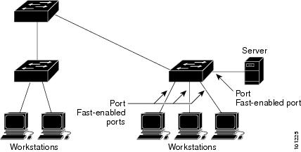
PortFast immediately brings an interface configured as an access or trunk port to the forwarding state from a blocking state, bypassing the listening and learning states.
Figure 1. PortFast-Enabled Interfaces. You can use PortFast on interfaces connected to a single workstation or server to allow those devices to immediately connect to the network, rather than waiting for the spanning tree to converge.Interfaces connected to a single workstation or server should not receive bridge protocol data units (BPDUs). An interface with PortFast enabled goes through the normal cycle of spanning-tree status changes when the switch is restarted.
You can enable this feature by enabling it on either the interface or on all nontrunking ports.
Related Tasks
Related References
BPDU Guard
The Bridge Protocol Data Unit (BPDU) guard feature can be globally enabled on the switch or can be enabled per port, but the feature operates with some differences.
When you enable BPDU guard at the global level on PortFast-enabled ports, spanning tree shuts down ports that are in a PortFast-operational state if any BPDU is received on them. In a valid configuration, PortFast-enabled ports do not receive BPDUs. Receiving a BPDU on a Port Fast-enabled port means an invalid configuration, such as the connection of an unauthorized device, and the BPDU guard feature puts the port in the error-disabled state. When this happens, the switch shuts down the entire port on which the violation occurred.
When you enable BPDU guard at the interface level on any port without also enabling the PortFast feature, and the port receives a BPDU, it is put in the error-disabled state.
The BPDU guard feature provides a secure response to invalid configurations because you must manually put the interface back in service. Use the BPDU guard feature in a service-provider network to prevent an access port from participating in the spanning tree.
Related Tasks
BPDU Filtering
The BPDU filtering feature can be globally enabled on the switch or can be enabled per interface, but the feature operates with some differences.
Enabling BPDU filtering on PortFast-enabled interfaces at the global level keeps those interfaces that are in a PortFast-operational state from sending or receiving BPDUs. The interfaces still send a few BPDUs at link-up before the switch begins to filter outbound BPDUs. You should globally enable BPDU filtering on a switch so that hosts connected to these interfaces do not receive BPDUs. If a BPDU is received on a PortFast-enabled interface, the interface loses its PortFast-operational status, and BPDU filtering is disabled.
Enabling BPDU filtering on an interface without also enabling the PortFast feature keeps the interface from sending or receiving BPDUs.
CautionEnabling BPDU filtering on an interface is the same as disabling spanning tree on it and can result in spanning-tree loops.
You can enable the BPDU filtering feature for the entire switch or for an interface.
Related Tasks
UplinkFast
Figure 2. Switches in a Hierarchical Network. Switches in hierarchical networks can be grouped into backbone switches, distribution switches, and access switches. This complex network has distribution switches and access switches that each have at least one redundant link that spanning tree blocks to prevent loops.If a switch loses connectivity, it begins using the alternate paths as soon as the spanning tree selects a new root port. You can accelerate the choice of a new root port when a link or switch fails or when the spanning tree reconfigures itself by enabling UplinkFast. The root port transitions to the forwarding state immediately without going through the listening and learning states, as it would with the normal spanning-tree procedures.
When the spanning tree reconfigures the new root port, other interfaces flood the network with multicast packets, one for each address that was learned on the interface. You can limit these bursts of multicast traffic by reducing the max-update-rate parameter (the default for this parameter is 150 packets per second). However, if you enter zero, station-learning frames are not generated, so the spanning-tree topology converges more slowly after a loss of connectivity.
UplinkFast provides fast convergence after a direct link failure and achieves load-balancing between redundant Layer 2 links using uplink groups. An uplink group is a set of Layer 2 interfaces (per VLAN), only one of which is forwarding at any given time. Specifically, an uplink group consists of the root port (which is forwarding) and a set of blocked ports, except for self-looping ports. The uplink group provides an alternate path in case the currently forwarding link fails.
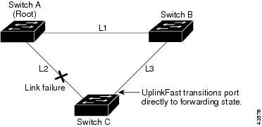
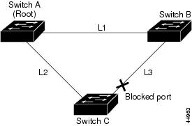
Figure 3. UplinkFast Example Before Direct Link Failure. This topology has no link failures. Switch A, the root switch, is connected directly to Switch B over link L1 and to Switch C over link L2. The Layer 2 interface on Switch C that is connected directly to Switch B is in a blocking state.Figure 4. UplinkFast Example After Direct Link Failure. If Switch C detects a link failure on the currently active link L2 on the root port (a direct link failure), UplinkFast unblocks the blocked interface on Switch C and transitions it to the forwarding state without going through the listening and learning states. This change takes approximately 1 to 5 seconds.Related Concepts
Cross-Stack UplinkFast
Cross-Stack UplinkFast (CSUF) provides a fast spanning-tree transition (fast convergence in less than 1 second under normal network conditions) across a switch stack. During the fast transition, an alternate redundant link on the switch stack is placed in the forwarding state without causing temporary spanning-tree loops or loss of connectivity to the backbone. With this feature, you can have a redundant and resilient network in some configurations. CSUF is automatically enabled when you enable the UplinkFast feature.
CSUF might not provide a fast transition all the time; in these cases, the normal spanning-tree transition occurs, completing in 30 to 40 seconds. For more information, see Related Topics.
Related Concepts
Related Tasks
How Cross-Stack UplinkFast Works
Cross-Stack UplinkFast (CSUF) ensures that one link in the stack is elected as the path to the root.
Figure 5. Cross-Stack UplinkFast Topology.The stack-root port on Switch 1 provides the path to the root of the spanning tree. The alternate stack-root ports on Switches 2 and 3 can provide an alternate path to the spanning-tree root if the current stack-root switch fails or if its link to the spanning-tree root fails.
Link 1, the root link, is in the spanning-tree forwarding state. Links 2 and 3 are alternate redundant links that are in the spanning-tree blocking state. If Switch 1 fails, if its stack-root port fails, or if Link 1 fails, CSUF selects either the alternate stack-root port on Switch 2 or Switch 3 and puts it into the forwarding state in less than 1 second.
When certain link loss or spanning-tree events occur (described in the following topic), the Fast Uplink Transition Protocol uses the neighbor list to send fast-transition requests to stack members.
The switch sending the fast-transition request needs to do a fast transition to the forwarding state of a port that it has chosen as the root port, and it must obtain an acknowledgment from each stack switch before performing the fast transition.
Each switch in the stack decides if the sending switch is a better choice than itself to be the stack root of this spanning-tree instance by comparing the root, cost, and bridge ID. If the sending switch is the best choice as the stack root, each switch in the stack returns an acknowledgment; otherwise, it sends a fast-transition request. The sending switch then has not received acknowledgments from all stack switches.
When acknowledgments are received from all stack switches, the Fast Uplink Transition Protocol on the sending switch immediately transitions its alternate stack-root port to the forwarding state. If acknowledgments from all stack switches are not obtained by the sending switch, the normal spanning-tree transitions (blocking, listening, learning, and forwarding) take place, and the spanning-tree topology converges at its normal rate (2 * forward-delay time + max-age time).
The Fast Uplink Transition Protocol is implemented on a per-VLAN basis and affects only one spanning-tree instance at a time.
Related Concepts
Related Tasks
Events That Cause Fast Convergence
Depending on the network event or failure, the CSUF fast convergence might or might not occur.
Fast convergence (less than 1 second under normal network conditions) occurs under these circumstances:
- The stack-root port link fails. If two switches in the stack have alternate paths to the root, only one of the switches performs the fast transition.
- The failed link, which connects the stack root to the spanning-tree root, recovers.
- A network reconfiguration causes a new stack-root switch to be selected.
- A network reconfiguration causes a new port on the current stack-root switch to be chosen as the stack-root port.
Normal spanning-tree convergence (30 to 40 seconds) occurs under these conditions:
Related Tasks
BackboneFast
BackboneFast detects indirect failures in the core of the backbone. BackboneFast is a complementary technology to the UplinkFast feature, which responds to failures on links directly connected to access switches. BackboneFast optimizes the maximum-age timer, which controls the amount of time the switch stores protocol information received on an interface. When a switch receives an inferior BPDU from the designated port of another switch, the BPDU is a signal that the other switch might have lost its path to the root, and BackboneFast tries to find an alternate path to the root.
BackboneFast starts when a root port or blocked interface on a switch receives inferior BPDUs from its designated switch. An inferior BPDU identifies a switch that declares itself as both the root bridge and the designated switch. When a switch receives an inferior BPDU, it means that a link to which the switch is not directly connected (an indirect link) has failed (that is, the designated switch has lost its connection to the root switch). Under spanning-tree rules, the switch ignores inferior BPDUs for the maximum aging time (default is 20 seconds).
The switch tries to find if it has an alternate path to the root switch. If the inferior BPDU arrives on a blocked interface, the root port and other blocked interfaces on the switch become alternate paths to the root switch. (Self-looped ports are not considered alternate paths to the root switch.) If the inferior BPDU arrives on the root port, all blocked interfaces become alternate paths to the root switch. If the inferior BPDU arrives on the root port and there are no blocked interfaces, the switch assumes that it has lost connectivity to the root switch, causes the maximum aging time on the root port to expire, and becomes the root switch according to normal spanning-tree rules.
If the switch has alternate paths to the root switch, it uses these alternate paths to send a root link query (RLQ) request. The switch sends the RLQ request on all alternate paths to learn if any stack member has an alternate root to the root switch and waits for an RLQ reply from other switches in the network and in the stack. The switch sends the RLQ request on all alternate paths and waits for an RLQ reply from other switches in the network.
When a stack member receives an RLQ reply from a nonstack member on a blocked interface and the reply is destined for another nonstacked switch, it forwards the reply packet, regardless of the spanning-tree interface state.
When a stack member receives an RLQ reply from a nonstack member and the response is destined for the stack, the stack member forwards the reply so that all the other stack members receive it.
If the switch discovers that it still has an alternate path to the root, it expires the maximum aging time on the interface that received the inferior BPDU. If all the alternate paths to the root switch indicate that the switch has lost connectivity to the root switch, the switch expires the maximum aging time on the interface that received the RLQ reply. If one or more alternate paths can still connect to the root switch, the switch makes all interfaces on which it received an inferior BPDU its designated ports and moves them from the blocking state (if they were in the blocking state), through the listening and learning states, and into the forwarding state.
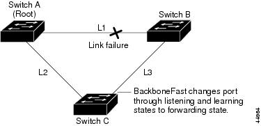
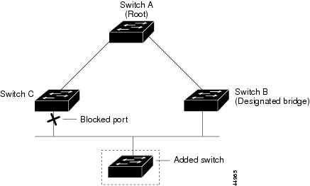
Figure 6. BackboneFast Example Before Indirect Link Failure. This is an example topology with no link failures. Switch A, the root switch, connects directly to Switch B over link L1 and to Switch C over link L2. The Layer 2 interface on Switch C that connects directly to Switch B is in the blocking state.Figure 7. BackboneFast Example After Indirect Link Failure. If link L1 fails, Switch C cannot detect this failure because it is not connected directly to link L1. However, because Switch B is directly connected to the root switch over L1, it detects the failure, elects itself the root, and begins sending BPDUs to Switch C, identifying itself as the root. When Switch C receives the inferior BPDUs from Switch B, Switch C assumes that an indirect failure has occurred. At that point, BackboneFast allows the blocked interface on Switch C to move immediately to the listening state without waiting for the maximum aging time for the interface to expire. BackboneFast then transitions the Layer 2 interface on Switch C to the forwarding state, providing a path from Switch B to Switch A. The root-switch election takes approximately 30 seconds, twice the Forward Delay time if the default Forward Delay time of 15 seconds is set. BackboneFast reconfigures the topology to account for the failure of link L1.Figure 8. Adding a Switch in a Shared-Medium Topology. If a new switch is introduced into a shared-medium topology, BackboneFast is not activated because the inferior BPDUs did not come from the recognized designated switch (Switch B). The new switch begins sending inferior BPDUs that indicate it is the root switch. However, the other switches ignore these inferior BPDUs, and the new switch learns that Switch B is the designated switch to Switch A, the root switch.EtherChannel Guard
You can use EtherChannel guard to detect an EtherChannel misconfiguration between the switch and a connected device. A misconfiguration can occur if the switch interfaces are configured in an EtherChannel, but the interfaces on the other device are not. A misconfiguration can also occur if the channel parameters are not the same at both ends of the EtherChannel.
If the switch detects a misconfiguration on the other device, EtherChannel guard places the switch interfaces in the error-disabled state, and displays an error message.
Related Tasks
Root Guard
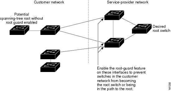
Figure 9. Root Guard in a Service-Provider Network.The Layer 2 network of a service provider (SP) can include many connections to switches that are not owned by the SP. In such a topology, the spanning tree can reconfigure itself and select a customer switch as the root switch. You can avoid this situation by enabling root guard on SP switch interfaces that connect to switches in your customer’s network. If spanning-tree calculations cause an interface in the customer network to be selected as the root port, root guard then places the interface in the root-inconsistent (blocked) state to prevent the customer’s switch from becoming the root switch or being in the path to the root.
If a switch outside the SP network becomes the root switch, the interface is blocked (root-inconsistent state), and spanning tree selects a new root switch. The customer’s switch does not become the root switch and is not in the path to the root.
If the switch is operating in multiple spanning-tree (MST) mode, root guard forces the interface to be a designated port. If a boundary port is blocked in an internal spanning-tree (IST) instance because of root guard, the interface also is blocked in all MST instances. A boundary port is an interface that connects to a LAN, the designated switch of which is either an IEEE 802.1D switch or a switch with a different MST region configuration.
Root guard enabled on an interface applies to all the VLANs to which the interface belongs. VLANs can be grouped and mapped to an MST instance.
CautionMisuse of the root guard feature can cause a loss of connectivity.
Related Tasks
Loop Guard
You can use loop guard to prevent alternate or root ports from becoming designated ports because of a failure that leads to a unidirectional link. This feature is most effective when it is enabled on the entire switched network. Loop guard prevents alternate and root ports from becoming designated ports, and spanning tree does not send BPDUs on root or alternate ports.
When the switch is operating in PVST+ or rapid-PVST+ mode, loop guard prevents alternate and root ports from becoming designated ports, and spanning tree does not send BPDUs on root or alternate ports.
When the switch is operating in MST mode, BPDUs are not sent on nonboundary ports only if the interface is blocked by loop guard in all MST instances. On a boundary port, loop guard blocks the interface in all MST instances.
Related Tasks
How to Configure Optional Spanning-Tree Features
Enabling PortFast (CLI)
SUMMARY STEPSAn interface with the PortFast feature enabled is moved directly to the spanning-tree forwarding state without waiting for the standard forward-time delay.
If you enable the voice VLAN feature, the PortFast feature is automatically enabled. When you disable voice VLAN, the PortFast feature is not automatically disabled.
You can enable this feature if your switch is running PVST+, Rapid PVST+, or MSTP.
Beginning in privileged EXEC mode, follow these steps to enable PortFast on the switch.
DETAILED STEPSYou can use the spanning-tree portfast default global configuration command to globally enable the PortFast feature on all nontrunking ports.
Related Concepts
Related References
Enabling BPDU Guard (CLI)
SUMMARY STEPSYou can enable the BPDU guard feature if your switch is running PVST+, Rapid PVST+, or MSTP.
CautionConfigure PortFast only on ports that connect to end stations; otherwise, an accidental topology loop could cause a data packet loop and disrupt switch and network operation.
Beginning in privileged EXEC mode, follow these steps to enable BPDU guard on the switch.
DETAILED STEPSWhat to Do Next
Command or Action Purpose
Step 1 configure terminal
Example:Switch# configure terminalStep 2 spanning-tree portfast bpduguard default
Example:Switch(config)# spanning-tree portfast bpduguard defaultStep 3 interface interface-id
Example:Switch(config)# interface gigabitethernet1/0/2Specifies the interface connected to an end station, and enters interface configuration mode.
Step 4 spanning-tree portfast
Example:Switch(config-if)# spanning-tree portfastStep 5 end
Example:Switch(config-if)# endTo prevent the port from shutting down, you can use the errdisable detect cause bpduguard shutdown vlan global configuration command to shut down just the offending VLAN on the port where the violation occurred.
You also can use the spanning-tree bpduguard enable interface configuration command to enable BPDU guard on any port without also enabling the PortFast feature. When the port receives a BPDU, it is put it in the error-disabled state.
Related Concepts
Enabling BPDU Filtering (CLI)
SUMMARY STEPSYou can also use the spanning-tree bpdufilter enable interface configuration command to enable BPDU filtering on any interface without also enabling the PortFast feature. This command prevents the interface from sending or receiving BPDUs.
CautionEnabling BPDU filtering on an interface is the same as disabling spanning tree on it and can result in spanning-tree loops.
You can enable the BPDU filtering feature if your switch is running PVST+, Rapid PVST+, or MSTP.
CautionConfigure PortFast only on interfaces that connect to end stations; otherwise, an accidental topology loop could cause a data packet loop and disrupt switch and network operation.
Beginning in privileged EXEC mode, follow these steps to enable BPDU filtering on the switch.
DETAILED STEPS
Command or Action Purpose
Step 1 configure terminal
Example:Switch# configure terminalStep 2 spanning-tree portfast bpdufilter default
Example:Switch(config)# spanning-tree portfast bpdufilter defaultStep 3 interface interface-id
Example:Switch(config)# interface gigabitethernet1/0/2Specifies the interface connected to an end station, and enters interface configuration mode.
Step 4 spanning-tree portfast
Example:Switch(config-if)# spanning-tree portfastStep 5 end
Example:Switch(config-if)# end
Enabling UplinkFast for Use with Redundant Links (CLI)
NoteWhen you enable UplinkFast, it affects all VLANs on the switch or switch stack. You cannot configure UplinkFast on an individual VLAN.
You can configure the UplinkFast or the Cross-Stack UplinkFast (CSUF) feature for Rapid PVST+ or for the MSTP, but the feature remains disabled (inactive) until you change the spanning-tree mode to PVST+.
This procedure is optional. Beginning in privileged EXEC mode, follow these steps to enable UplinkFast and CSUF.
Before You BeginSUMMARY STEPSUplinkFast cannot be enabled on VLANs that have been configured with a switch priority. To enable UplinkFast on a VLAN with switch priority configured, first restore the switch priority on the VLAN to the default value using the no spanning-tree vlan vlan-id priority global configuration command.
DETAILED STEPS
Command or Action Purpose
Step 1 configure terminal
Example:Switch# configure terminalStep 2 spanning-tree uplinkfast [max-update-rate pkts-per-second]
Example:Switch(config)# spanning-tree uplinkfast max-update-rate 200(Optional) For pkts-per-second, the range is 0 to 32000 packets per second; the default is 150.
If you set the rate to 0, station-learning frames are not generated, and the spanning-tree topology converges more slowly after a loss of connectivity.
When you enter this command, CSUF also is enabled on all nonstack port interfaces.
Step 3 end
Example:Switch(config)# endWhen UplinkFast is enabled, the switch priority of all VLANs is set to 49152. If you change the path cost to a value less than 3000 and you enable UplinkFast or UplinkFast is already enabled, the path cost of all interfaces and VLAN trunks is increased by 3000 (if you change the path cost to 3000 or above, the path cost is not altered). The changes to the switch priority and the path cost reduce the chance that a switch will become the root switch.
When UplinkFast is disabled, the switch priorities of all VLANs and path costs of all interfaces are set to default values if you did not modify them from their defaults.
When you enable the UplinkFast feature using these instructions, CSUF is automatically globally enabled on nonstack port interfaces.
Disabling UplinkFast (CLI)
SUMMARY STEPSThis procedure is optional.
Beginning in privileged EXEC mode, follow these steps to disable UplinkFast and Cross-Stack UplinkFast (CSUF).
DETAILED STEPS
Command or Action Purpose When UplinkFast is disabled, the switch priorities of all VLANs and path costs of all interfaces are set to default values if you did not modify them from their defaults.
When you disable the UplinkFast feature using these instructions, CSUF is automatically globally disabled on nonstack port interfaces.
Enabling BackboneFast (CLI)
You can enable BackboneFast to detect indirect link failures and to start the spanning-tree reconfiguration sooner.
You can configure the BackboneFast feature for Rapid PVST+ or for the MSTP, but the feature remains disabled (inactive) until you change the spanning-tree mode to PVST+.
This procedure is optional. Beginning in privileged EXEC mode, follow these steps to enable BackboneFast on the switch.
Before You BeginSUMMARY STEPSIf you use BackboneFast, you must enable it on all switches in the network. BackboneFast is not supported on Token Ring VLANs. This feature is supported for use with third-party switches.
DETAILED STEPS
Command or Action Purpose Related Concepts
Enabling EtherChannel Guard (CLI)
SUMMARY STEPSYou can enable EtherChannel guard to detect an EtherChannel misconfiguration if your switch is running PVST+, Rapid PVST+, or MSTP.
Beginning in privileged EXEC mode, follow these steps to enable EtherChannel Guard on the switch.
DETAILED STEPSWhat to Do Next
Command or Action Purpose You can use the show interfaces status err-disabled privileged EXEC command to show which switch ports are disabled because of an EtherChannel misconfiguration. On the remote device, you can enter the show etherchannel summary privileged EXEC command to verify the EtherChannel configuration.
After the configuration is corrected, enter the shutdown and no shutdown interface configuration commands on the port-channel interfaces that were misconfigured.
Related Concepts
Enabling Root Guard (CLI)
SUMMARY STEPSRoot guard enabled on an interface applies to all the VLANs to which the interface belongs. Do not enable the root guard on interfaces to be used by the UplinkFast feature. With UplinkFast, the backup interfaces (in the blocked state) replace the root port in the case of a failure. However, if root guard is also enabled, all the backup interfaces used by the UplinkFast feature are placed in the root-inconsistent state (blocked) and are prevented from reaching the forwarding state.
NoteYou cannot enable both root guard and loop guard at the same time.
You can enable this feature if your switch is running PVST+, Rapid PVST+, or MSTP.
Beginning in privileged EXEC mode, follow these steps to enable root guard on the switch.
DETAILED STEPS
Command or Action Purpose
Step 1 configure terminal
Example:Switch# configure terminalStep 2 interface interface-id
Example:Switch(config)# interface gigabitethernet1/0/2Specifies an interface to configure, and enters interface configuration mode.
Step 3 spanning-tree guard root
Example:Switch(config-if)# spanning-tree guard rootStep 4 end
Example:Switch(config-if)# end
Enabling Loop Guard (CLI)
SUMMARY STEPSYou can use loop guard to prevent alternate or root ports from becoming designated ports because of a failure that leads to a unidirectional link. This feature is most effective when it is configured on the entire switched network. Loop guard operates only on interfaces that are considered point-to-point by the spanning tree.
NoteYou cannot enable both loop guard and root guard at the same time.
You can enable this feature if your switch is running PVST+, Rapid PVST+, or MSTP.
This procedure is optional. Beginning in privileged EXEC mode, follow these steps to enable loop guard on the switch.
DETAILED STEPS
Command or Action Purpose
Step 1 Enter one of the following commands:
Example:Switch# show spanning-tree activeSwitch# show spanning-tree mstStep 2 configure terminal
Example:Switch# configure terminalStep 3 spanning-tree loopguard default
Example:Switch(config)# spanning-tree loopguard defaultStep 4 end
Example:Switch(config)# end
Monitoring the Spanning-Tree Status
Additional References for Optional Spanning Tree Features
Error Message Decoder
Description Link To help you research and resolve system error messages in this release, use the Error Message Decoder tool.
https://www.cisco.com/cgi-bin/Support/Errordecoder/index.cgi
MIBs
Technical Assistance
Description Link The Cisco Support website provides extensive online resources, including documentation and tools for troubleshooting and resolving technical issues with Cisco products and technologies.
To receive security and technical information about your products, you can subscribe to various services, such as the Product Alert Tool (accessed from Field Notices), the Cisco Technical Services Newsletter, and Really Simple Syndication (RSS) Feeds.
Access to most tools on the Cisco Support website requires a Cisco.com user ID and password.