- Preface
- New and Changed Information
- Overview
- Configuring Layer 2 Switching
- Configuring VLANs
- Configuring MVRP
- Configuring VTP
- Configuring Private VLANs Using NX-OS
- Configuring Rapid PVST+ Using Cisco NX-OS
- Configuring MST Using Cisco NX-OS
- Configuring STP Extensions Using Cisco NX-OS
- Configuration Limits for Layer 2 Switching
Cisco Nexus 7000 Series NX-OS Layer 2 Switching Configuration Guide
Bias-Free Language
The documentation set for this product strives to use bias-free language. For the purposes of this documentation set, bias-free is defined as language that does not imply discrimination based on age, disability, gender, racial identity, ethnic identity, sexual orientation, socioeconomic status, and intersectionality. Exceptions may be present in the documentation due to language that is hardcoded in the user interfaces of the product software, language used based on RFP documentation, or language that is used by a referenced third-party product. Learn more about how Cisco is using Inclusive Language.
- Updated:
- July 18, 2014
Chapter: Configuring Rapid PVST+ Using Cisco NX-OS
- Finding Feature Information
- Information About Rapid PVST+
- STP
- Rapid PVST+
- Rapid PVST+ and IEEE 802.1Q Trunks
- Rapid PVST+ Interoperation with Legacy 802.1D STP
- Rapid PVST+ Interoperation with 802.1s MST
- High Availability for Rapid PVST+
- Virtualization Support for Rapid PVST+
- Licensing Requirements for Rapid PVST+
- Prerequisites for Configuring Rapid PVST+
- Guidelines and Limitations for Configuring Rapid PVST+
- Default Settings for Rapid PVST+
- Configuring Rapid PVST+
- Guidelines for Configuring Rapid PVST+
- Enabling Rapid PVST+—CLI Version
- Disabling or Enabling Rapid PVST+ Per VLAN—CLI Version
- Configuring the Root Bridge ID
- Configuring a Secondary Root Bridge—CLI Version
- Configuring the Rapid PVST+ Bridge Priority of a VLAN
- Configuring the Rapid PVST+ Port Priority—CLI Version
- Configuring the Rapid PVST+ Path-Cost Method and Port Cost—CLI Version
- Configuring the Rapid PVST+ Hello Time for a VLAN—CLI Version
- Configuring the Rapid PVST+ Forward Delay Time for a VLAN—CLI Version
- Configuring the Rapid PVST+ Maximum Age Time for a VLAN—CLI Version
- Specifying the Link Type for Rapid PVST+—CLI Version
- Reinitializing the Protocol for Rapid PVST+
- Verifying the Rapid PVST+ Configurations
- Displaying and Clearing Rapid PVST+ Statistics—CLI Version
- Rapid PVST+ Example Configurations
- Additional References for Rapid PVST+—CLI Version
- Feature History for Configuring Rapid PVST+—CLI Version
Configuring Rapid PVST+ Using Cisco NX-OS
This chapter describes how to configure the Rapid per VLAN Spanning Tree (Rapid PVST+) protocol on Cisco NX-OS devices.
This chapter includes the following sections:
- Finding Feature Information
- Information About Rapid PVST+
- Licensing Requirements for Rapid PVST+
- Prerequisites for Configuring Rapid PVST+
- Guidelines and Limitations for Configuring Rapid PVST+
- Default Settings for Rapid PVST+
- Configuring Rapid PVST+
- Verifying the Rapid PVST+ Configurations
- Displaying and Clearing Rapid PVST+ Statistics—CLI Version
- Rapid PVST+ Example Configurations
- Additional References for Rapid PVST+—CLI Version
- Feature History for Configuring Rapid PVST+—CLI Version
Finding Feature Information
Your software release might not support all the features documented in this module. For the latest caveats and feature information, see the Bug Search Tool at https://tools.cisco.com/bugsearch/ and the release notes for your software release. To find information about the features documented in this module, and to see a list of the releases in which each feature is supported, see the “New and Changed Information” chapter or the Feature History table below.
Information About Rapid PVST+
 Note | See the Cisco Nexus 7000 Series NX-OS Interfaces Configuration Guide for information on creating Layer 2 interfaces. |
The Spanning Tree Protocol (STP) was implemented to provide a loop-free network at Layer 2 of the network. Rapid PVST+ is an updated implementation of STP that allows you to create one spanning tree topology for each VLAN. Rapid PVST+ is the default STP mode on the device.
Note | Spanning tree is used to refer to IEEE 802.1w and IEEE 802.1s. If the IEEE 802.1D Spanning Tree Protocol is discussed in this publication, then 802.1D is stated specifically. |
Note | You can run either Rapid PVST+ or MST within each virtual device context (VDC). You cannot run both STP modes simultaneously in a VDC. Rapid PVST+ is the default STP mode. |
The Rapid PVST+ protocol is the IEEE 802.1w standard, Rapid Spanning Tree Protocol (RSTP), implemented on a per VLAN basis. Rapid PVST+ interoperates with the IEEE 802.1Q VLAN standard, which mandates a single STP instance for all VLANs, rather than per VLAN.
Rapid PVST+ is enabled by default on the default VLAN (VLAN1) and on all newly created VLANs on the device. Rapid PVST+ interoperates with devices that run legacy IEEE 802.1D STP.
RSTP is an improvement on the original STP standard, 802.1D, which allows faster convergence.
Note | The device supports full nondisruptive upgrades for Rapid PVST+. See the Cisco Nexus 7000 Series NX-OS High Availability and Redundancy Guide for complete information on nondisruptive upgrades. |
The Cisco NX-OS release that is running on a managed device may not support all the features or settings described in this chapter. For the latest feature information and caveats, see the documentation and release notes for your platform and software release.
Note | Beginning with Cisco NX-OS Release 5.x, when you are running virtual port channels (vPCs), you can configure STP for better performance. See the Cisco Nexus 7000 Series NX-OS Interfaces Configuration Guide for more information on this feature. |
- STP
- Rapid PVST+
- Rapid PVST+ and IEEE 802.1Q Trunks
- Rapid PVST+ Interoperation with Legacy 802.1D STP
- Rapid PVST+ Interoperation with 802.1s MST
- High Availability for Rapid PVST+
- Virtualization Support for Rapid PVST+
STP
STP is a Layer 2 link-management protocol that provides path redundancy while preventing loops in the network.
- Overview of STP
- How a Topology is Created
- Bridge ID
- BPDUs
- Election of the Root Bridge
- Creating the Spanning Tree Topology
Overview of STP
In order for a Layer 2 Ethernet network to function properly, only one active path can exist between any two stations. STP operation is transparent to end stations, which cannot detect whether they are connected to a single LAN segment or a switched LAN of multiple segments.
When you create fault-tolerant internetworks, you must have a loop-free path between all nodes in a network. The STP algorithm calculates the best loop-free path throughout a switched Layer 2 network. Layer 2 LAN ports send and receive STP frames, which are called Bridge Protocol Data Units (BPDUs), at regular intervals. Network devices do not forward these frames but use the frames to construct a loop-free path.
Multiple active paths between end stations cause loops in the network. If a loop exists in the network, end stations might receive duplicate messages and network devices might learn end station MAC addresses on multiple Layer 2 LAN ports.
STP defines a tree with a root bridge and a loop-free path from the root to all network devices in the Layer 2 network. STP forces redundant data paths into a blocked state. If a network segment in the spanning tree fails and a redundant path exists, the STP algorithm recalculates the spanning tree topology and activates the blocked path.
When two Layer 2 LAN ports on a network device are part of a loop, the STP port priority and port path-cost setting determine which port on the device is put in the forwarding state and which port is put in the blocking state. The STP port priority value is the efficiency with which that location allows the port to pass traffic. The STP port path-cost value is derived from the media speed.
How a Topology is Created
All devices in a LAN that participate in a spanning tree gather information about other switches in the network by exchanging BPDUs. This exchange of BPDUs results in the following actions:
-
The system elects a unique root switch for the spanning tree network topology.
-
The system elects a designated switch for each LAN segment.
-
The system eliminates any loops in the switched network by placing redundant switch ports in a backup state; all paths that are not needed to reach the root device from anywhere in the switched network are placed in an STP-blocked state.
The topology on an active switched network is determined by the following:
-
The unique device identifier Media Access Control (MAC) address of the device that is associated with each device
-
The path cost to the root that is associated with each switch port
-
The port identifier that is associated with each switch port
In a switched network, the root switch is the logical center of the spanning tree topology. STP uses BPDUs to elect the root switch and root port for the switched network.
Note | The mac-address bpdu source version 2 command enables STP to use the new Cisco MAC address (00:26:0b:xx:xx:xx) as the source address of BPDUs generated on vPC ports. To apply this command, you must have identical configurations for both vPC peer switches or peers. We strongly recommend that you disable EtherChannel Guard on the edge devices before using this command to minimize traffic disruption from STP inconsistencies. Reenable the EtherChannel Guard after updating on both peers. |
Bridge ID
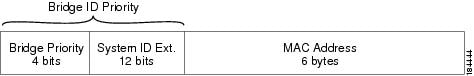
Each VLAN on each network device has a unique 64-bit bridge ID that consists of a bridge priority value, an extended system ID (IEEE 802.1t), and an STP MAC address allocation.
Bridge Priority Value
The bridge priority is a 4-bit value when the extended system ID is enabled.
You can only specify a device bridge ID (used by the spanning tree algorithm to determine the identity of the root bridge; the lowest number is preferred) as a multiple of 4096.
Note | In this device, the extended system ID is always enabled; you cannot disable the extended system ID. |
Extended System ID
The device always uses the 12-bit extended system ID.
|
Bridge Priority Value |
Extended System ID (Set Equal to the VLAN ID) |
|||||||||||||||
|---|---|---|---|---|---|---|---|---|---|---|---|---|---|---|---|---|
|
Bit 16 |
Bit 15 |
Bit 14 |
Bit 13 |
Bit 12 |
Bit 11 |
Bit 10 |
Bit 9 |
Bit 8 |
Bit 7 |
Bit 6 |
Bit 5 |
Bit 4 |
Bit 3 |
Bit 2 |
Bit 1 |
|
|
32768 |
16384 |
8192 |
4096 |
2048 |
1024 |
512 |
256 |
128 |
64 |
32 |
16 |
8 |
4 |
2 |
1 |
|
STP MAC Address Allocation
Note | MAC address reduction is always enabled on the device. |
Because MAC address reduction is always enabled on the device, you should also enable MAC address reduction on all other Layer 2 connected network devices to avoid undesirable root bridge election and spanning tree topology issues.
When MAC address reduction is enabled, the root bridge priority becomes a multiple of 4096 plus the VLAN ID. You can only specify a device bridge ID (used by the spanning tree algorithm to determine the identity of the root bridge; the lowest number is preferred) as a multiple of 4096. Only the following values are possible:
STP uses the extended system ID plus a MAC address to make the bridge ID unique for each VLAN.
Note | If another bridge in the same spanning tree domain does not run the MAC address reduction feature, it could win the root bridge ownership because of the finer granularity in the selection of its bridge ID. |
BPDUs
Network devices transmit BPDUs throughout the STP instance. Each network device sends configuration BPDUs to communicate and compute the spanning tree topology. Each configuration BPDU contains the following minimal information:
-
The unique bridge ID of the network device that the transmitting network device believes to be the root bridge
-
The STP path cost to the root
-
The bridge ID of the transmitting bridge
-
The message age
-
The identifier of the transmitting port
-
Values for the hello, forward delay, and max-age protocol timer
-
Additional information for STP extension protocols
When a network device transmits a Rapid PVST+ BPDU frame, all network devices connected to the VLAN on which the frame is transmitted receive the BPDU. When a network device receives a BPDU, it does not forward the frame but instead uses the information in the frame to calculate a BPDU. If the topology changes, the device initiates a BPDU exchange.
A BPDU exchange results in the following:
-
One network device is elected as the root bridge.
-
The shortest distance to the root bridge is calculated for each network device based on the path cost.
-
A designated bridge for each LAN segment is selected. This network device is closest to the root bridge through which frames are forwarded to the root.
-
A root port is elected. This port provides the best path from the bridge to the root bridge.
-
Ports included in the spanning tree are selected.
Election of the Root Bridge
For each VLAN, the network device with the highest bridge ID (that is, the lowest numerical ID value) is elected as the root bridge. If all network devices are configured with the default priority (32768), the network device with the lowest MAC address in the VLAN becomes the root bridge. The bridge priority value occupies the most significant bits of the bridge ID.
When you change the bridge priority value, you change the probability that the device will be elected as the root bridge. Configuring a lower value increases the probability; a higher value decreases the probability.
The STP root bridge is the logical center of each spanning tree topology in a Layer 2 network. All paths that are not needed to reach the root bridge from anywhere in the Layer 2 network are placed in STP blocking mode.
BPDUs contain information about the transmitting bridge and its ports, including bridge and MAC addresses, bridge priority, port priority, and path cost. STP uses this information to elect the root bridge for the STP instance, to elect the root port that leads to the root bridge, and to determine the designated port for each Layer 2 segment.
Creating the Spanning Tree Topology
By increasing the priority (lowering the numerical value) of the ideal network device so that it becomes the root bridge, you force an STP recalculation to form a new spanning tree topology with the ideal network device as the root.
When the spanning tree topology is calculated based on default parameters, the path between the source and destination end stations in a switched network might not be ideal. For instance, connecting higher-speed links to a port that has a higher number than the current root port can cause a root-port change. The goal is to make the fastest link the root port.
For example, assume that one port on switch B is a fiber-optic link, and another port on switch B (an unshielded twisted-pair [UTP] link) is the root port. Network traffic might be more efficient over the high-speed fiber-optic link. By changing the STP port priority on the fiber-optic port to a higher priority (lower numerical value) than the root port, the fiber-optic port becomes the new root port.
Rapid PVST+
Rapid PVST+ is the default spanning tree mode for the software and is enabled by default on the default VLAN and all newly created VLANs.
A single instance, or topology, of RSTP runs on each configured VLAN, and each Rapid PVST+ instance on a VLAN has a single root device. You can enable and disable STP on a per-VLAN basis when you are running Rapid PVST+.
- Overview of Rapid PVST+
- Rapid PVST+ BPDUs
- Proposal and Agreement Handshake
- Protocol Timers
- Port Roles
- Rapid PVST+ Port State Overview
- Synchronization of Port Roles
- Detecting Unidirectional Link Failure:Rapid PVST+
- Port Cost
- Port Priority
Overview of Rapid PVST+
Rapid PVST+ is the IEEE 802.1w (RSTP) standard implemented per VLAN. A single instance of STP runs on each configured VLAN (if you do not manually disable STP). Each Rapid PVST+ instance on a VLAN has a single root switch. You can enable and disable STP on a per-VLAN basis when you are running Rapid PVST+.
Note | Rapid PVST+ is the default STP mode for the device. |
Rapid PVST+ uses point-to-point wiring to provide rapid convergence of the spanning tree. The spanning tree reconfiguration can occur in less than 1 second with Rapid PVST+ (in contrast to 50 seconds with the default settings in the 802.1D STP). The device automatically checks the PVID.
Note | Rapid PVST+ supports one STP instance for each VLAN. |
Using Rapid PVST+, STP convergence occurs rapidly. By default, each designated port in the STP sends out a BPDU every 2 seconds. On a designated port in the topology, if hello messages are missed three consecutive times, or if the maximum age expires, the port immediately flushes all protocol information in the table. A port considers that it loses connectivity to its direct neighbor designated port if it misses three BPDUs or if the maximum age expires. This rapid aging of the protocol information allows quick failure detection.
Rapid PVST+ provides for rapid recovery of connectivity following the failure of a device, a device port, or a LAN. It provides rapid convergence for edge ports, new root ports, and ports connected through point-to-point links as follows:
-
Edge ports—When you configure a port as an edge port on an RSTP device, the edge port immediately transitions to the forwarding state. (This immediate transition was previously a Cisco-proprietary feature named PortFast.) You should only configure ports that connect to a single end station as edge ports. Edge ports do not generate topology changes when the link changes.
Enter the spanning-tree port type interface configuration command to configure a port as an STP edge port.
Note | We recommend that you configure all ports connected to a Layer 2 host as edge ports. |
-
Root port—If Rapid PVST+ selects a new root port, it blocks the old root port and immediately transitions the new root port to the forwarding state.
-
Point-to-point links—If you connect a port to another port through a point-to-point link and the local port becomes a designated port, it negotiates a rapid transition with the other port by using the proposal-agreement handshake to ensure a loop-free topology.
Rapid PVST+ achieves rapid transition to the forwarding state only on edge ports and point-to-point links. Although the link type is configurable, the system automatically derives the link type information from the duplex setting of the port. Full-duplex ports are assumed to be point-to-point ports, while half-duplex ports are assumed to be shared ports.
Edge ports do not generate topology changes, but all other designated and root ports generate a topology change (TC) BPDU when they either fail to receive three consecutive BPDUs from the directly connected neighbor or the maximum age times out. At this point, the designated or root port sends a BPDU with the TC flag set. The BPDUs continue to set the TC flag as long as the TC While timer runs on that port. The value of the TC While timer is the value set for the hello time plus 1 second. The initial detector of the topology change immediately floods this information throughout the entire topology.
When Rapid PVST+ detects a topology change, the protocol does the following:
-
Starts the TC While timer with a value equal to twice the hello time for all the nonedge root and designated ports, if necessary.
-
Flushes the MAC addresses associated with all these ports.
The topology change notification floods quickly across the entire topology. The system flushes dynamic entries immediately on a per-port basis when it receives a topology change.
Note | The TCA flag is used only when the device is interacting with devices that are running legacy 802.1D STP. |
The proposal and agreement sequence then quickly propagates toward the edge of the network and quickly restores connectivity after a topology change.
Rapid PVST+ BPDUs
Rapid PVST+ and 802.1w use all six bits of the flag byte to add the following:
This figure shows the use of the BPDU flags in Rapid PVST+.
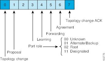
Another important change is that the Rapid PVST+ BPDU is type 2, version 2, which makes it possible for the device to detect connected legacy (802.1D) bridges. The BPDU for 802.1D is type 0, version 0.
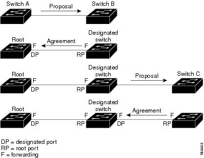
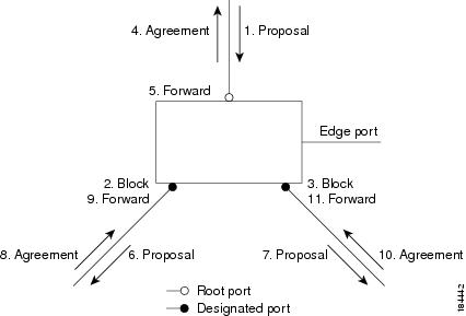
Proposal and Agreement Handshake
In this figure, switch A is connected to switch B through a point-to-point link, and all of the ports are in the blocking state. Assume that the priority of switch A is a smaller numerical value than the priority of switch B. Switch A sends a proposal message (a configuration BPDU with the proposal flag set) to switch B, proposing itself as the designated switch.
After receiving the proposal message, switch B selects as its new root port the port from which the proposal message was received, forces all nonedge ports to the blocking state, and sends an agreement message (a BPDU with the agreement flag set) through its new root port.
After receiving the agreement message from switch B, switch A also immediately transitions its designated port to the forwarding state. No loops in the network can form because switch B blocked all of its nonedge ports and because there is a point-to-point link between switches A and B.
When switch C connects to switch B, a similar set of handshaking messages are exchanged. Switch C selects the port connected to switch B as its root port, and both ends of the link immediately transition to the forwarding state. With each iteration of this handshaking process, one more switch joins the active topology. As the network converges, this proposal-agreement handshaking progresses from the root toward the leaves of the spanning tree as shown in this figure.
The switch learns the link type from the port duplex mode; a full-duplex port is considered to have a point-to-point connection and a half-duplex port is considered to have a shared connection. You can override the default setting that is controlled by the duplex setting by entering the spanning-tree link-type interface configuration command.
This proposal/agreement handshake is initiated only when a nonedge port moves from the blocking to the forwarding state. The handshaking process then proliferates step-by-step throughout the topology.
Protocol Timers
|
Variable |
Description |
|---|---|
|
Hello timer |
Determines how often each device broadcasts BPDUs to other network devices. The default is 2 seconds, and the range is from 1 to 10. |
|
Forward delay timer |
Determines how long each of the listening and learning states last before the port begins forwarding. This timer is generally not used by the protocol, but it is used when interoperating with the 802.1D spanning tree. The default is 15 seconds, and the range is from 4 to 30 seconds. |
|
Maximum age timer |
Determines the amount of time that protocol information received on a port is stored by the network device. This timer is generally not used by the protocol, but it is used when interoperating with the 802.1D spanning tree. The default is 20 seconds; the range is from 6 to 40 seconds. |
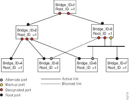
Port Roles
Rapid PVST+ provides rapid convergence of the spanning tree by assigning port roles and learning the active topology. Rapid PVST+ builds upon the 802.1D STP to select the device with the highest switch priority (lowest numerical priority value) as the root bridge. Rapid PVST+ assigns one of these port roles to individual ports:
-
Root port—Provides the best path (lowest cost) when the device forwards packets to the root bridge.
-
Designated port—Connects to the designated device that has the lowest path cost when forwarding packets from that LAN to the root bridge. The port through which the designated device is attached to the LAN is called the designated port.
-
Alternate port—Offers an alternate path toward the root bridge to the path provided by the current root port. An alternate port provides a path to another device in the topology.
-
Backup port—Acts as a backup for the path provided by a designated port toward the leaves of the spanning tree. A backup port can exist only when two ports are connected in a loopback by a point-to-point link or when a device has two or more connections to a shared LAN segment. A backup port provides another path in the topology to the device.
-
Disabled port—Has no role within the operation of the spanning tree.
In a stable topology with consistent port roles throughout the network, Rapid PVST+ ensures that every root port and designated port immediately transition to the forwarding state while all alternate and backup ports are always in the blocking state. Designated ports start in the blocking state. The port state controls the operation of the forwarding and learning processes.
Rapid PVST+ Port State Overview
Propagation delays can occur when protocol information passes through a switched LAN. As a result, topology changes can take place at different times and at different places in a switched network. When a Layer 2 LAN port transitions directly from nonparticipation in the spanning tree topology to the forwarding state, it can create temporary data loops. Ports must wait for new topology information to propagate through the switched LAN before starting to forward frames.
Each Layer 2 LAN port on the device that uses Rapid PVST+ or MST exists in one of the following four states:
-
Blocking—The Layer 2 LAN port does not participate in frame forwarding.
-
Learning—The Layer 2 LAN port prepares to participate in frame forwarding.
-
Forwarding—The Layer 2 LAN port forwards frames.
-
Disabled—The Layer 2 LAN port does not participate in STP and is not forwarding frames.
When you enable Rapid PVST+, every port in the device, VLAN, and network goes through the blocking state and the transitory states of learning at power up. If properly configured, each Layer 2 LAN port stabilizes to the forwarding or blocking state.
When the STP algorithm places a Layer 2 LAN port in the forwarding state, the following process occurs:
-
The Layer 2 LAN port is put into the blocking state while it waits for protocol information that suggests it should go to the learning state.
-
The Layer 2 LAN port waits for the forward delay timer to expire, moves the Layer 2 LAN port to the learning state, and restarts the forward delay timer.
-
In the learning state, the Layer 2 LAN port continues to block frame forwarding as it learns the end station location information for the forwarding database.
-
The Layer 2 LAN port waits for the forward delay timer to expire and then moves the Layer 2 LAN port to the forwarding state, where both learning and frame forwarding are enabled.
Blocking State
A Layer 2 LAN port in the blocking state does not participate in frame forwarding.
A Layer 2 LAN port in the blocking state performs as follows:
-
Discards frames received from the attached segment.
-
Discards frames switched from another port for forwarding.
-
Does not incorporate the end station location into its address database. (There is no learning on a blocking Layer 2 LAN port, so there is no address database update.)
-
Receives BPDUs and directs them to the system module.
-
Receives, processes, and transmits BPDUs received from the system module.
-
Receives and responds to control plane messages.
Learning State
A Layer 2 LAN port in the learning state prepares to participate in frame forwarding by learning the MAC addresses for the frames. The Layer 2 LAN port enters the learning state from the blocking state.
A Layer 2 LAN port in the learning state performs as follows:
-
Discards frames received from the attached segment.
-
Discards frames switched from another port for forwarding.
-
Incorporates the end station location into its address database.
-
Receives BPDUs and directs them to the system module.
-
Receives, processes, and transmits BPDUs received from the system module.
-
Receives and responds to control plane messages.
Forwarding State
A Layer 2 LAN port in the forwarding state forwards frames. The Layer 2 LAN port enters the forwarding state from the learning state.
A Layer 2 LAN port in the forwarding state performs as follows:
-
Forwards frames received from the attached segment.
-
Forwards frames switched from another port for forwarding.
-
Incorporates the end station location information into its address database.
-
Receives BPDUs and directs them to the system module.
-
Processes BPDUs received from the system module.
-
Receives and responds to control plane messages.
Disabled State
A Layer 2 LAN port in the disabled state does not participate in frame forwarding or STP. A Layer 2 LAN port in the disabled state is virtually nonoperational.
A disabled Layer 2 LAN port performs as follows:
-
Discards frames received from the attached segment.
-
Discards frames switched from another port for forwarding.
-
Does not incorporate the end station location into its address database. (There is no learning, so there is no address database update.)
-
Does not receive BPDUs from neighbors.
-
Does not receive BPDUs for transmission from the system module.
Summary of Port States
|
Operational Status |
Port State |
Is Port Included in the Active Topology? |
|---|---|---|
|
Enabled |
Blocking |
No |
|
Enabled |
Learning |
Yes |
|
Enabled |
Forwarding |
Yes |
|
Disabled |
Disabled |
No |
Synchronization of Port Roles
When the device receives a proposal message on one of its ports and that port is selected as the new root port, Rapid PVST+ forces all other ports to synchronize with the new root information.
The device is synchronized with superior root information received on the root port if all other ports are synchronized. An individual port on the device is synchronized if either of the following applies:
-
That port is in the blocking state.
-
It is an edge port (a port configured to be at the edge of the network).
If a designated port is in the forwarding state and is not configured as an edge port, it transitions to the blocking state when the Rapid PVST+ forces it to synchronize with new root information. In general, when the Rapid PVST+ forces a port to synchronize with root information and the port does not satisfy any of the above conditions, its port state is set to blocking.
After ensuring that all of the ports are synchronized, the device sends an agreement message to the designated device that corresponds to its root port. When the devices connected by a point-to-point link are in agreement about their port roles, Rapid PVST+ immediately transitions the port states to the forwarding state.
Processing Superior BPDU Information
A superior BPDU is a BPDU with root information (such as a lower switch ID or lower path cost) that is superior to what is currently stored for the port.
If a port receives a superior BPDU, Rapid PVST+ triggers a reconfiguration. If the port is proposed and is selected as the new root port, Rapid PVST+ forces all the designated, nonedge ports to synchronize.
If the received BPDU is a Rapid PVST+ BPDU with the proposal flag set, the device sends an agreement message after all of the other ports are synchronized. The new root port transitions to the forwarding state as soon as the previous port reaches the blocking state.
If the superior information received on the port causes the port to become a backup port or an alternate port, Rapid PVST+ sets the port to the blocking state and sends an agreement message. The designated port continues sending BPDUs with the proposal flag set until the forward-delay timer expires. At that time, the port transitions to the forwarding state.
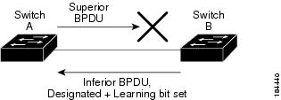
Processing Inferior BPDU Information
An inferior BPDU is a BPDU with root information (such as a higher switch ID or higher path cost) that is inferior to what is currently stored for the port.
If a designated port receives an inferior BPDU, it immediately replies with its own information.
Detecting Unidirectional Link Failure:Rapid PVST+
The software checks the consistency of the port role and state in the received BPDUs to detect unidirectional link failures that could cause bridging loops using the Unidirectional Link Detection (UDLD) feature. This feature is based on the dispute mechanism.
See the Cisco Nexus 7000 Series NX-OS Interfaces Configuration Guide for information on UDLD.
When a designated port detects a conflict, it keeps its role, but reverts to a discarding state because disrupting connectivity in case of inconsistency is preferable to opening a bridging loop.
Port Cost
Note | Rapid PVST+ uses the short (16-bit) path-cost method to calculate the cost by default. With the short path-cost method, you can assign any value in the range of 1 to 65535. However, you can configure the device to use the long (32-bit) path-cost method, which allows you to assign any value in the range of 1 to 200,000,000. You configure the path-cost calculation method globally. |
|
Bandwidth |
Short Path-Cost Method of Port Cost |
Long Path-Cost Method of Port Cost |
|---|---|---|
|
10 Mbps |
100 |
2,000,000 |
|
100 Mbps |
19 |
200,000 |
|
1 Gigabit Ethernet |
4 |
20,000 |
|
10 Gigabit Ethernet |
2 |
2,000 |
If a loop occurs, STP considers the port cost when selecting a LAN interface to put into the forwarding state.
You can assign the lower cost values to LAN interfaces that you want STP to select first and higher cost values to LAN interfaces that you want STP to select last. If all LAN interfaces have the same cost value, STP puts the LAN interface with the lowest LAN interface number in the forwarding state and blocks other LAN interfaces.
On access ports, you assign the port cost by the port. On trunk ports, you assign the port cost by the VLAN; you can configure the same port cost to all the VLANs on a trunk port.
Port Priority
If a redundant path occurs and multiple ports have the same path cost, Rapid PVST+ considers the port priority when selecting which LAN port to put into the forwarding state. You can assign lower priority values to LAN ports that you want Rapid PVST+ to select first and higher priority values to LAN ports that you want Rapid PVST+ to select last.
If all LAN ports have the same priority value, Rapid PVST+ puts the LAN port with the lowest LAN port number in the forwarding state and blocks other LAN ports. The possible priority range is from 0 through 224 (the default is 128), configurable in increments of 32. The device uses the port priority value when the LAN port is configured as an access port and uses the VLAN port priority values when the LAN port is configured as a trunk port.
Rapid PVST+ and IEEE 802.1Q Trunks
The 802.1Q trunks impose some limitations on the STP strategy for a network. In a network of Cisco network devices connected through 802.1Q trunks, the network devices maintain one instance of STP for each VLAN allowed on the trunks. However, non-Cisco 802.1Q network devices maintain only one instance of STP for all VLANs allowed on the trunks, which is the Common Spanning Tree (CST).
When you connect a Cisco network device to a non-Cisco device through an 802.1Q trunk, the Cisco network device combines the STP instance of the 802.1Q VLAN of the trunk with the STP instance of the non-Cisco 802.1Q network device. However, all per-VLAN STP information that is maintained by Cisco network devices is separated by a cloud of non-Cisco 802.1Q network devices. The non-Cisco 802.1Q cloud that separates the Cisco network devices is treated as a single trunk link between the network devices.
For more information on 802.1Q trunks, see the Cisco Nexus 7000 Series NX-OS Interfaces Configuration Guide.
Rapid PVST+ Interoperation with Legacy 802.1D STP
Rapid PVST+ can interoperate with devices that are running the legacy 802.1D protocol. The device knows that it is interoperating with equipment running 802.1D when it receives a BPDU version 0. The BPDUs for Rapid PVST+ are version 2. If the BPDU received is an 802.1w BPDU version 2 with the proposal flag set, the device sends an agreement message after all of the other ports are synchronized. If the BPDU is an 802.1D BPDU version 0, the device does not set the proposal flag and starts the forward-delay timer for the port. The new root port requires twice the forward-delay time to transition to the forwarding state.
The device interoperates with legacy 802.1D devices as follows:
-
Notification—Unlike 802.1D BPDUs, 802.1w does not use TCN BPDUs. However, for interoperability with 802.1D devices, the device processes and generates TCN BPDUs.
-
Acknowledgment—When an 802.1w device receives a TCN message on a designated port from an 802.1D device, it replies with an 802.1D configuration BPDU with the TCA bit set. However, if the TC-while timer (the same as the TC timer in 802.1D) is active on a root port connected to an 802.1D device and a configuration BPDU with the TCA set is received, the TC-while timer is reset.
This method of operation is required only for 802.1D devices. The 802.1w BPDUs do not have the TCA bit set.
-
Protocol migration—For backward compatibility with 802.1D devices, 802.1w selectively sends 802.1D configuration BPDUs and TCN BPDUs on a per-port basis.
When a port is initialized, the migrate-delay timer is started (specifies the minimum time during which 802.1w BPDUs are sent), and 802.1w BPDUs are sent. While this timer is active, the device processes all BPDUs received on that port and ignores the protocol type.
If the device receives an 802.1D BPDU after the port migration-delay timer has expired, it assumes that it is connected to an 802.1D device and starts using only 802.1D BPDUs. However, if the 802.1w device is using 802.1D BPDUs on a port and receives an 802.1w BPDU after the timer has expired, it restarts the timer and starts using 802.1w BPDUs on that port.
Note | If you want all devices on the same LAN segment to reinitialize the protocol on each interface, you must reinitialize Rapid PVST+. |
Rapid PVST+ Interoperation with 802.1s MST
Rapid PVST+ interoperates seamlessly with the IEEE 802.1s Multiple Spanning Tree (MST) standard. No user configuration is needed. To disable this seamless interoperation, you can use PVST Simulation.
High Availability for Rapid PVST+
The software supports high availability for Rapid PVST+. However, the statistics and timers are not restored when Rapid PVST+ restarts. The timers start again and the statistics begin from 0.
Note | See the Cisco Nexus 7000 Series NX-OS High Availability and Redundancy Guide for complete information on high-availability features. |
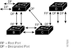
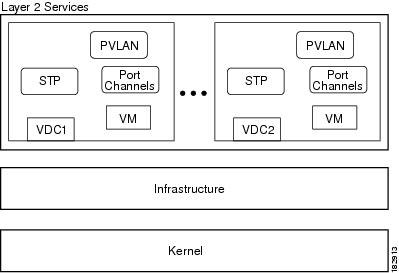
Virtualization Support for Rapid PVST+
Note | See the Cisco Nexus 7000 Series NX-OS Virtual Device Context Configuration Guide for complete information on virtual device contexts (VDCs) and assigning resources. |
This figure shows how the system provides support for VDCs. Using VDCs, you have a separate Layer 2 virtualization in each VDC, and each VDC runs a separate STP.
Each VDC will have its own Rapid PVST+. You cannot configure Rapid PVST+ across VDCs with Cisco NX-OS software. However, you can run Rapid PVST+ in one VDC and run MST in each VDC.
For example, VDC1 can run MST, VDC2 can run Rapid PVST+, and VDC3 can run MST.
Ensure that you are in the correct VDC before you begin configuring either Rapid PVST+ parameters.
Licensing Requirements for Rapid PVST+
The following table shows the licensing requirements for this feature:
|
Product |
License Requirement |
|---|---|
|
Cisco NX-OS |
Rapid PVST+ requires no license. Any feature not included in a license package is bundled with the Cisco NX-OS system images and is provided at no extra charge to you. For a complete explanation of the Cisco NX-OS licensing scheme, see Cisco NX-OS Licensing Guide. |
However, using VDCs requires an Advanced Services license.
Prerequisites for Configuring Rapid PVST+
Rapid PVST+ has the following prerequisites:
Guidelines and Limitations for Configuring Rapid PVST+
Rapid PVST+ has the following configuration guidelines and limitations:
-
There is a total of 4000 Rapid PVST+ for each VDC.
-
The maximum number of VLANs and ports is 16,000.
-
Only Rapid PVST+ or MST can be active at any time for each VDC.
-
Port channeling—The port-channel bundle is considered as a single port. The port cost is the aggregation of all the configured port costs assigned to that channel.
-
For private VLANs, on a normal VLAN trunk port, the primary and secondary private VLANs are two different logical ports and must have the exact STP topology. On access ports, STP sees only the primary VLAN.
-
We recommend that you configure all ports connected to Layer 2 hosts as STP edge ports.
-
Always leave STP enabled.
-
Do not change timers because changing timers can adversely affect stability.
-
Keep user traffic off the management VLAN; keep the management VLAN separate from the user data.
-
Choose the distribution and core layers as the location of the primary and secondary root switches.
-
When you connect two Cisco devices through 802.1Q trunks, the switches exchange spanning tree BPDUs on each VLAN allowed on the trunks. The BPDUs on the native VLAN of the trunk are sent untagged to the reserved 802.1D spanning tree multicast MAC address (01-80-C2-00-00-00). The BPDUs on all VLANs on the trunk are sent tagged to the reserved Cisco Shared Spanning Tree Protocol (SSTP) multicast MAC address (01-00-0c-cc-cc-cd).
Default Settings for Rapid PVST+
Configuring Rapid PVST+
Rapid PVST+, which has the 802.1 w standard applied to the PVST+ protocol, is the default STP setting in the device.
You enable Rapid PVST+ on a per-VLAN basis. The device maintains a separate instance of STP for each VLAN (except on those VLANS on which you disable STP). By default, Rapid PVST+ is enabled on the default VLAN and on each VLAN that you create.
Note | If you are familiar with the Cisco IOS CLI, be aware that the Cisco NX-OS commands for this feature might differ from the Cisco IOS commands that you would use. |
- Guidelines for Configuring Rapid PVST+
- Enabling Rapid PVST+—CLI Version
- Disabling or Enabling Rapid PVST+ Per VLAN—CLI Version
- Configuring the Root Bridge ID
- Configuring a Secondary Root Bridge—CLI Version
- Configuring the Rapid PVST+ Bridge Priority of a VLAN
- Configuring the Rapid PVST+ Port Priority—CLI Version
- Configuring the Rapid PVST+ Path-Cost Method and Port Cost—CLI Version
- Configuring the Rapid PVST+ Hello Time for a VLAN—CLI Version
- Configuring the Rapid PVST+ Forward Delay Time for a VLAN—CLI Version
- Configuring the Rapid PVST+ Maximum Age Time for a VLAN—CLI Version
- Specifying the Link Type for Rapid PVST+—CLI Version
- Reinitializing the Protocol for Rapid PVST+
Guidelines for Configuring Rapid PVST+
Ensure that you are in the correct VDC (see the Cisco Nexus 7000 Series NX-OS Virtual Device Context Configuration Guide).
Enabling Rapid PVST+—CLI Version
If you disable Rapid PVST+ on any VLANs, you must reenable Rapid PVRST+ on the specified VLANs. If you have enabled MST on the device and now want to use Rapid PVST+, you must enable Rapid PVST+ on the device.
Rapid PVST+ is the default STP mode. You cannot simultaneously run MST and Rapid PVST+ in the same VDC.
However, one VDC can run Rapid PVST+ and a different VDC can run MST.
Note | When you change the spanning tree mode, traffic is disrupted because all spanning tree instances are stopped for the previous mode and started for the new mode. |
Ensure that you are in the correct VDC (or enter the switchto vdc command).
| Command or Action | Purpose | |||
|---|---|---|---|---|
| Step 1 |
config t
Example: switch# config t switch(config)# |
Enters global configuration mode. | ||
| Step 2 |
spanning-tree mode rapid-pvst
Example: switch(config)# spanning-tree mode rapid-pvst |
Enables Rapid PVST+ on the device. Rapid PVST+ is the default spanning tree mode.
| ||
| Step 3 |
exit
Example: switch(config)# exit switch# |
Exits global configuration mode. | ||
| Step 4 |
show running-config spanning-tree all
Example: switch# show running-config spanning-tree all | (Optional)
Displays information about the currently running STP configuration. | ||
| Step 5 |
copy running-config startup-config
Example: switch# copy running-config startup-config | (Optional)
Copies the running configuration to the startup configuration. |
This example shows how to enable Rapid PVST+ on the device:
switch# config t switch(config)# spanning-tree mode rapid-pvst switch(config)# exit switch#
Note | Because Rapid PVST+ is enabled by default, entering the show running command to view the resulting configuration does not display the command that you entered to enable Rapid PVST+. |
Disabling or Enabling Rapid PVST+ Per VLAN—CLI Version
You can enable or disable Rapid PVST+ on each VLAN.
Note | Rapid PVST+ is enabled by default on the default VLAN and on all VLANs that you create. |
Ensure that you are in the correct VDC (or enter the switchto vdc command).
| Command or Action | Purpose | |||||||
|---|---|---|---|---|---|---|---|---|
| Step 1 |
config t
Example: switch# config t switch(config)# |
Enters global configuration mode. | ||||||
| Step 2 | Enter one of the following
commands:
Example: switch(config)# spanning-tree vlan 5 | |||||||
| Step 3 |
exit
Example: switch(config)# exit switch# |
Exits global configuration mode. | ||||||
| Step 4 |
show spanning-tree
Example: switch# show spanning-tree | (Optional)
Displays the STP configuration. | ||||||
| Step 5 |
copy running-config
startup-config
Example: switch# copy running-config startup-config | (Optional)
Copies the running configuration to the startup configuration. |
This example shows how to enable STP on VLAN 5:
switch# config t switch(config)# spanning-tree vlan 5 switch(config)# exit switch#
Note | Do not disable spanning tree on a VLAN unless all switches and bridges in the VLAN have spanning tree disabled. You cannot disable spanning tree on some switches and bridges in a VLAN and leave it enabled on other switches and bridges in the VLAN. This action can have unexpected results because switches and bridges with spanning tree enabled will have incomplete information regarding the physical topology of the network. |
 Caution | We do not recommend disabling spanning tree even in a topology that is free of physical loops. Spanning tree serves as a safeguard against misconfigurations and cabling errors. Do not disable spanning tree in a VLAN without ensuring that no physical loops are present in the VLAN. |
Note | Because STP is enabled by default, entering the show running command to view the resulting configuration does not display the command that you entered to enable STP. |
Configuring the Root Bridge ID
The device maintains a separate instance of STP for each active VLAN in Rapid PVST+. For each VLAN, the network device with the lowest bridge ID becomes the root bridge for that VLAN.
To configure a VLAN instance to become the root bridge, modify the bridge priority from the default value (32768) to a significantly lower value.
When you enter the spanning-tree vlan vlan_ID primary root command, the device checks the bridge priority of the current root bridges for each VLAN. The device sets the bridge priority for the specified VLANs to 24576 if this value will cause the device to become the root for the specified VLANs. If any root bridge for the specified VLAN has a bridge priority lower than 24576, the device sets the bridge priority for the specified VLANs to 4096 less than the lowest bridge priority.
Note | The spanning-tree vlan vlan_ID primary root command fails if the value required to be the root bridge is less than 4096. If the software cannot lower the bridge priority any lower, the device returns the following message: Error: Failed to set root bridge for VLAN 1 It may be possible to make the bridge root by setting the priority for some (or all) of these instances to zero. |
Caution | The root bridge for each instance of STP should be a backbone or distribution device. Do not configure an access device as the STP primary root. |
Enter the diameter keyword to specify the Layer 2 network diameter (that is, the maximum number of bridge hops between any two end stations in the Layer 2 network). When you specify the network diameter, the software automatically selects an optimal hello time, forward delay time, and maximum age time for a network of that diameter, which can significantly reduce the STP convergence time. You can enter the hello-time keyword to override the automatically calculated hello time.
Note | With the device configured as the root bridge, do not manually configure the hello time, forward-delay time, and maximum-age time using the spanning-tree mst hello-time, spanning-tree mst forward-time, and spanning-tree mst max-age global configuration commands. |
Ensure that you are in the correct VDC (or enter the switchto vdc command).
| Command or Action | Purpose | |
|---|---|---|
| Step 1 |
config
t
Example: switch# config t switch(config)# |
Enters global configuration mode. |
| Step 2 |
spanning-tree vlan
vlan-range
root
primary [diameter
dia
[hello-time
hello-time]]
Example: switch(config)# spanning-tree vlan 5 root primary diameter 4 |
Configures a device as the primary root bridge. The vlan-range value can be 2 through 4094 (except for reserved VLAN values.) The dia default is 7. The hello-time can be from 1 to 10 seconds, and the default value is 2 seconds. |
| Step 3 |
exit
Example: switch(config)# exit switch# |
Exits global configuration mode. |
| Step 4 |
show
spanning-tree
Example: switch# show spanning-tree | (Optional)
Displays the STP configuration. |
| Step 5 |
copy
running-config startup-config
Example: switch# copy running-config startup-config | (Optional)
Copies the running configuration to the startup configuration. |
This example shows how to configure the device as the root bridge for VLAN 5 with a network diameter of 4:
switch# config t switch(config)# spanning-tree vlan 5 root primary diameter 4 switch(config)# exit switch#
Configuring a Secondary Root Bridge—CLI Version
When you configure a device as the secondary root, the STP bridge priority is modified from the default value (32768) so that the device is likely to become the root bridge for the specified VLANs if the primary root bridge fails (assuming the other network devices in the network use the default bridge priority of 32768). STP sets the bridge priority to 28672.
Enter the diameter keyword to specify the Layer 2 network diameter (that is, the maximum number of bridge hops between any two end stations in the Layer 2 network). When you specify the network diameter, the software automatically selects an optimal hello time, forward delay time, and maximum age time for a network of that diameter, which can significantly reduce the STP convergence time. You can enter the hello-time keyword to override the automatically calculated hello time.
You can configure more than one device in this manner to have multiple backup root bridges. Enter the same network diameter and hello time values that you used when configuring the primary root bridge.
Note | With the device configured as the root bridge, do not manually configure the hello time, forward-delay time, and maximum-age time using the spanning-tree mst hello-time, spanning-tree mst forward-time, and spanning-tree mst max-age global configuration commands. |
Ensure that you are in the correct VDC (or enter the switchto vdc command).
| Command or Action | Purpose | |
|---|---|---|
| Step 1 |
config t
Example: switch# config t switch(config)# |
Enters global configuration mode. |
| Step 2 |
spanning-tree vlan
vlan-range
root
secondary [diameter
dia
[hello-time
hello-time]]
Example: switch(config)# spanning-tree vlan 5 root secondary diameter 4 |
Configures a device as the secondary root bridge. The vlan-range value can be 2 through 4094 (except for reserved VLAN values). The dia default is 7. The hello-time can be from 1 to 10 seconds, and the default value is 2 seconds. |
| Step 3 |
exit
Example: switch(config)# exit switch# |
Exits global configuration mode. |
| Step 4 |
show spanning-tree vlan
vlan_id
Example: switch# show spanning-tree vlan 5 | (Optional)
Displays the STP configuration for the specified VLANs. |
| Step 5 |
copy running-config
startup-config
Example: switch# copy running-config startup-config | (Optional)
Copies the running configuration to the startup configuration. |
This example shows how to configure the device as the secondary root bridge for VLAN 5 with a network diameter of 4:
switch# config t switch(config)# spanning-tree vlan 5 root secondary diameter 4 switch(config)# exit switch#
Configuring the Rapid PVST+ Bridge Priority of a VLAN
You can configure the Rapid PVST+ bridge priority of a VLAN. This is another method of configuring root bridges.
Note | Be careful when using this configuration. We recommend that you configure the primary root and secondary root to modify the bridge priority. |
Ensure that you are in the correct VDC (or enter the switchto vdc command).
| Command or Action | Purpose | |
|---|---|---|
| Step 1 |
config t
Example: switch# config t switch(config)# |
Enters global configuration mode. |
| Step 2 |
spanning-tree vlan
vlan-range
priority
value
Example: switch(config)# spanning-tree vlan 5 priority 8192 |
Configures the bridge priority of a VLAN. Valid values are 0, 4096, 8192, 12288, 16384, 20480, 24576, 28672, 32768, 36864, 40960, 45056, 49152, 53248, 57344, and 61440. All other values are rejected. The default value is 32768. |
| Step 3 |
exit
Example: switch(config)# exit switch# |
Exits global configuration mode. |
| Step 4 |
show spanning-tree vlan
vlan_id
Example: switch# show spanning-tree vlan 5 | (Optional)
Displays the STP configuration for the specified VLANs. |
| Step 5 |
copy running-config startup-config
Example: switch# copy running-config startup-config | (Optional)
Copies the running configuration to the startup configuration. |
This example shows how to configure the priority of VLAN 5 on Gigabit Ethernet port 1/4 to 8192:
switch# config t switch(config)# spanning-tree vlan 5 priority 8192 switch(config)# exit switch#
Configuring the Rapid PVST+ Port Priority—CLI Version
You can assign lower priority values to LAN ports that you want Rapid PVST+ to select first and higher priority values to LAN ports that you want Rapid PVST+ to select last. If all LAN ports have the same priority value, Rapid PVST+ puts the LAN port with the lowest LAN port number in the forwarding state and blocks other LAN ports.
The device uses the port priority value when the LAN port is configured as an access port and uses the VLAN port priority values when the LAN port is configured as a trunk port.
Ensure that you are in the correct VDC (or enter the switchto vdc command).
| Command or Action | Purpose | |
|---|---|---|
| Step 1 |
config t
Example: switch# config t switch(config)# |
Enters global configuration mode. |
| Step 2 |
interface
type slot/port
Example: switch(config)# interface ethernet 1/4 switch(config-if)# |
Specifies the interface to configure and enters interface configuration mode. |
| Step 3 |
spanning-tree
[vlan
vlan-list]
port-priority
priority
Example: switch(config-if)# spanning-tree port-priority 160 |
Configures the port priority for the LAN interface. The priority value can be from 0 to 224. A lower value indicates a higher priority. The priority values are 0, 32, 64, 96, 128, 160, 192, and 224. All other values are rejected. The default value is 128. |
| Step 4 |
exit
Example: switch(config-if)# exit switch(config)# |
Exits interface configuration mode. |
| Step 5 |
show spanning-tree interface
{ethernet
slot/port |
port channel
channel-number}
Example: switch# show spanning-tree interface ethernet 2/10 | (Optional)
Displays the STP configuration for the specified interface. |
| Step 6 |
copy running-config
startup-config
Example: switch(config)# copy running-config startup-config | (Optional)
Copies the running configuration to the startup configuration. |
This example shows how to configure the port priority of Ethernet access port 1/4 to 160:
switch# config t switch (config)# interface ethernet 1/4 switch(config-if)# spanning-tree port-priority 160 switch(config-if)# exit switch(config)#
Configuring the Rapid PVST+ Path-Cost Method and Port Cost—CLI Version
On access ports, you can assign the port cost for each port. On trunk ports, you can assign the port cost for each VLAN; you can configure all the VLANs on a trunk with the same port cost.
Note | In Rapid PVST+ mode, you can use either the short or long path-cost method, and you can configure the method in either the interface or configuration submode. The default path-cost method is short. |
Ensure that you are in the correct VDC (or enter the switchto vdc command).
| Command or Action | Purpose | |||
|---|---|---|---|---|
| Step 1 |
config t
Example: switch# config t switch(config)# |
Enters global configuration mode. | ||
| Step 2 |
spanning-tree pathcost
method
{long
| short}
Example: switch(config)# spanning-tree pathcost method long |
Selects the method used for Rapid PVST+ path-cost calculations. The default method is the short method. | ||
| Step 3 |
interface
type slot/port
Example: switch(config)# interface ethernet 1/4 switch(config-if) |
Specifies the interface to configure and enters the interface configuration mode. | ||
| Step 4 |
spanning-tree
[vlan
vlan-id] cost
[value | auto]
Example: switch(config-if)# spanning-tree cost 1000 |
Configures the port cost for the LAN interface. The cost value, depending on the path-cost calculation method, can be as follows:
The default is auto, which sets the port cost on both the path-cost calculation method and the media speed. | ||
| Step 5 |
exit
Example: switch(config-if)# exit switch(config)# |
Exits interface configuration mode. | ||
| Step 6 |
show spanning-tree pathcost
method
Example: switch# show spanning-tree pathcost method | (Optional)
Displays the STP path-cost method. | ||
| Step 7 |
copy running-config
startup-config
Example: switch(config)# copy running-config startup-config | (Optional)
Copies the running configuration to the startup configuration. |
This example shows how to configure the port cost of Ethernet access port 1/4 to 1000:
switch# config t switch (config)# spanning-tree pathcost method long switch (config)# interface ethernet 1/4 switch(config-if)# spanning-tree cost 1000 switch(config-if)# exit switch(config)#
Configuring the Rapid PVST+ Hello Time for a VLAN—CLI Version
You can configure the Rapid-PVST+ hello time for a VLAN.
Note | Be careful when using this configuration because you might disrupt the Spanning Tree. For most situations, we recommend that you configure the primary root and secondary root to modify the hello time. |
Ensure that you are in the correct VDC (or enter the switchto vdc command).
| Command or Action | Purpose | |
|---|---|---|
| Step 1 |
config t
Example: switch# config t switch(config)# |
Enters global configuration mode. |
| Step 2 |
spanning-tree vlan
vlan-range
hello-time
value
Example: switch(config)# spanning-tree vlan 5 hello-time 7 |
Configures the hello time of a VLAN. The hello time value can be from 1 to 10 seconds, and the default is 2 seconds. |
| Step 3 |
exit
Example: switch(config)# exit switch# |
Exits global configuration mode. |
| Step 4 |
show spanning-tree vlan
vlan_id
Example: switch# show spanning-tree vlan 5 | (Optional)
Displays the STP configuration per VLAN. |
| Step 5 |
copy running-config
startup-config
Example: switch# copy running-config startup-config | (Optional)
Copies the running configuration to the startup configuration. |
This example shows how to configure the hello time for VLAN 5 to 7 seconds:
switch# config t switch(config)# spanning-tree vlan 5 hello-time 7 switch(config)# exit switch#
Configuring the Rapid PVST+ Forward Delay Time for a VLAN—CLI Version
You can configure the forward delay time per VLAN when using Rapid PVST+.
Ensure that you are in the correct VDC (or enter the switchto vdc command).
| Command or Action | Purpose | |
|---|---|---|
| Step 1 |
config t
Example: switch# config t switch(config)# |
Enters global configuration mode. |
| Step 2 |
spanning-tree vlan
vlan-range
forward-time
value
Example: switch(config)# spanning-tree vlan 5 forward-time 21 |
Configures the forward delay time of a VLAN. The forward delay time value can be from 4 to 30 seconds, and the default is 15 seconds. |
| Step 3 |
exit
Example: switch(config)# exit switch# |
Exits global configuration mode. |
| Step 4 |
show spanning-tree vlan
vlan_id
Example: switch# show spanning-tree vlan 5 | (Optional)
Displays the STP configuration per VLAN. |
| Step 5 |
copy running-config startup-config
Example: switch# copy running-config startup-config | (Optional)
Copies the running configuration to the startup configuration. |
This example shows how to configure the forward delay time for VLAN 5 to 21 seconds:
switch# config t switch(config)# spanning-tree vlan 5 forward-time 21 switch(config)# exit switch#
Configuring the Rapid PVST+ Maximum Age Time for a VLAN—CLI Version
You can configure the maximum age time per VLAN when using Rapid PVST+.
Ensure that you are in the correct VDC (or enter the switchto vdc command).
| Command or Action | Purpose | |
|---|---|---|
| Step 1 |
config t
Example: switch# config t switch(config)# |
Enters global configuration mode. |
| Step 2 |
spanning-tree vlan
vlan-range
max-age
value
Example: switch(config)# spanning-tree vlan 5 max-age 36 |
Configures the maximum aging time of a VLAN. The maximum aging time value can be from 6 to 40 seconds, and the default is 20 seconds. |
| Step 3 |
exit
Example: switch(config)# exit switch# |
Exits global configuration mode. |
| Step 4 |
show spanning-tree vlan
vlan_id
Example: switch# show spanning-tree vlan 5 | (Optional)
Displays the STP configuration per VLAN. |
| Step 5 |
copy running-config startup-config
Example: switch# copy running-config startup-config | (Optional)
Copies the running configuration to the startup configuration. |
This example shows how to configure the maximum aging time for VLAN 5 to 36 seconds:
switch# config t switch(config)# spanning-tree vlan 5 max-age 36 switch(config)# exit switch#
Specifying the Link Type for Rapid PVST+—CLI Version
Rapid connectivity (802.1w standard) is established only on point-to-point links. By default, the link type is controlled from the duplex mode of the interface. A full-duplex port is considered to have a point-to-point connection; a half-duplex port is considered to have a shared connection.
If you have a half-duplex link physically connected point to point to a single port on a remote device, you can override the default setting on the link type and enable rapid transitions.
If you set the link to shared, STP falls back to 802.1D.
Ensure that you are in the correct VDC (or enter the switchto vdc command).
| Command or Action | Purpose | |
|---|---|---|
| Step 1 |
config t
Example: switch# config t switch(config)# |
Enters global configuration mode. |
| Step 2 |
interface
type slot/port
Example: switch(config)# interface ethernet 1/4 switch(config-if)# |
Specifies the interface to configure and enters interface configuration mode. |
| Step 3 |
spanning-tree link-type
{auto |
point-to-point |
shared}
Example: switch(config-if)# spanning-tree link-type point-to-point |
Configures the link type to be either a point-to-point link or shared link. The system reads the default value from the device connection, as follows: half duplex links are shared and full-duplex links are point to point. If the link type is shared, the STP falls back to 802.1D. The default is auto, which sets the link type based on the duplex setting of the interface. |
| Step 4 |
exit
Example: switch(config-if)# exit switch(config)# |
Exits interface configuration mode. |
| Step 5 |
show spanning-tree
Example: switch# show spanning-tree | (Optional)
Displays the STP configuration. |
| Step 6 |
copy running-config
startup-config
Example: switch(config)# copy running-config startup-config | (Optional)
Copies the running configuration to the startup configuration. |
This example shows how to configure the link type as a point-to-point link:
switch# config t
switch (config)# interface ethernet 1/4
switch(config-if)# spanning-tree link-type point-to-point
switch(config-if)# exit
switch(config)#
Reinitializing the Protocol for Rapid PVST+
A bridge that runs Rapid PVST+ can send 802.1D BPDUs on one of its ports when it is connected to a legacy bridge. However, the STP protocol migration cannot determine whether the legacy device has been removed from the link unless the legacy device is the designated switch. You can reinitialize the protocol negotiation (force the renegotiation with neighboring devices) on the entire device or on specified interfaces.
Ensure that you are in the correct VDC (or enter the switchto vdc command).
| Command or Action | Purpose |
|---|
This example shows how to reinitialize Rapid PVST+ on the Ethernet interface on slot 2, port 8:
switch# clear spanning-tree detected-protocol interface ethernet 2/8
switch#
Verifying the Rapid PVST+ Configurations
|
Command |
Purpose |
|---|---|
|
show running-config spanning-tree [ all] |
Displays STP information. |
|
show spanning-tree summary |
Displays summary STP information. |
|
show spanning-tree detail |
Displays detailed STP information. |
|
show spanning-tree{vlanvlan-id | interface {[ethernetslot/port] | [port-channelchannel-number]}} [detail] |
Displays STP information per VLAN and interface. |
|
show spanning-tree vlan vlan-id bridge |
Displays information on the STP bridge. |
For information about the fields in the output from these commands, see the Cisco Nexus 7000 Series NX-OS Layer 2 Switching Command Reference.
Displaying and Clearing Rapid PVST+ Statistics—CLI Version
|
Command |
Purpose |
|---|---|
|
clear spanning-tree counters [interface type slot/port | vlan vlan-id] |
Clears the counters for STP. |
| show spanning-tree {vlan vlan-id | interface {[ethernet slot/port] | [port-channel channel-number]}} detail |
Displays information about STP by interface or VLAN including BPDUs sent and received. |
Rapid PVST+ Example Configurations
The following example shows how to configure Rapid PVST+:
switch# configure terminal
switch(config)# spanning-tree port type edge bpduguard default
switch(config)# spanning-tree port type edge bpdufilter default
switch(cnfig)# spanning-tree port type network default
switch(config)# spanning-tree vlan 1-10 priority 24576
switch(config)# spanning-tree vlan 1-10 hello-time 1
switch(config)# spanning-tree vlan 1-10 forward-time 9
switch(config)# spanning-tree vlan 1-10 max-age 13

switch(config)# interface Ethernet 3/1 switchport
switch(config-if)# spanning-tree port type edge
switch(config-if)# exit

switch(config)# spanning-tree port type edge
switch(config-if)# switchport
switch(config-if)# switchport mode trunk
switch(config-if)# spanning-tree guard root
switch(config-if)# exit
switch(config)#
Additional References for Rapid PVST+—CLI Version
Related Documents
|
Related Topic |
Document Title |
|---|---|
|
Command reference |
Cisco Nexus 7000 Series NX-OS Layer 2 Switching Command Reference |
|
Layer 2 interfaces |
Cisco Nexus 7000 Series NX-OS Interfaces Configuration Guide |
|
NX-OS fundamentals |
Cisco Nexus 7000 Series NX-OS Fundamentals Configuration Guide |
|
High availability |
Cisco Nexus 7000 Series NX-OS High Availability and Redundancy Guide |
|
System management |
Cisco Nexus 7000 Series NX-OS System Management Configuration Guide |
|
VDCs |
Cisco Nexus 7000 Series NX-OS Virtual Device Context Configuration Guide |
|
Licensing |
Cisco NX-OS Licensing Guide |
|
Release notes |
Cisco Nexus 7000 Series NX-OS Release Notes |
Standards
|
Standards |
Title |
|---|---|
|
IEEE 802.1Q-2006 (formerly known as IEEE 802.1s), IEEE 802.1D-2004 (formerly known as IEEE 802.1w), IEEE 802.1D, IEEE 802.1t |
— |
MIBs
|
MIBs |
MIBs Link |
|---|---|
|
To locate and download MIBs, go to the following URL: http://www.cisco.com/public/sw-center/netmgmt/cmtk/mibs.shtml |
Feature History for Configuring Rapid PVST+—CLI Version
This table includes only the updates for those releases that have resulted in additions or changes to the feature.
|
Feature Name |
Releases |
Feature Information |
|---|---|---|
|
No change |
4.2(1) |
-- |
|
No change |
4.1(2) |
-- |
 Feedback