Cisco Nexus 7000 Series NX-OS OTV Configuration Guide
Bias-Free Language
The documentation set for this product strives to use bias-free language. For the purposes of this documentation set, bias-free is defined as language that does not imply discrimination based on age, disability, gender, racial identity, ethnic identity, sexual orientation, socioeconomic status, and intersectionality. Exceptions may be present in the documentation due to language that is hardcoded in the user interfaces of the product software, language used based on RFP documentation, or language that is used by a referenced third-party product. Learn more about how Cisco is using Inclusive Language.
- Updated:
- December 3, 2011
Chapter: Configuring Basic OTV Features
- Information About Basic OTV Features
- Licensing Requirements for OTV
- Prerequisites for OTV
- Guidelines and Limitations for OTV
- Default Settings for OTV
- Configuring Basic OTV Features
- Enabling the OTV Feature
- Creating an Overlay Interface
- Configuring the Multicast Group Address
- Assigning a Physical Interface to the Overlay Interface
- Assigning the Extended VLAN Range
- Configuring the Site VLAN and Site Identifier
- Preparing OTV for ISSU to Cisco NX-OS 5.2(1) or Later Release in a Dual-Homed Site
- Verifying the OTV Configuration
- Configuration Examples for OTV
- Additional References
- Feature History for OTV
Configuring Basic OTV Features
This chapter describes how to configure basic Overlay Transport Virtualization (OTV) features on Cisco NX-OS devices.
- Information About Basic OTV Features
- Licensing Requirements for OTV
- Prerequisites for OTV
- Guidelines and Limitations for OTV
- Default Settings for OTV
- Configuring Basic OTV Features
- Verifying the OTV Configuration
- Configuration Examples for OTV
- Additional References
- Feature History for OTV
Information About Basic OTV Features
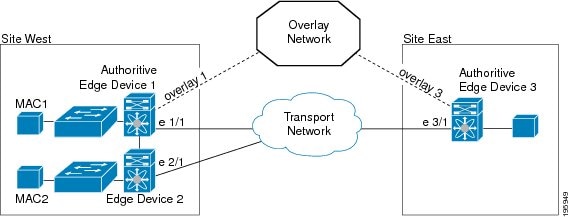
The overlay network consists of one or more logical overlay interfaces that are created on the edge device in each remote site that connects to the physical transport network. You associate the logical overlay interface with a physical interface that connects to the transport network. The OTV control plane is responsible for discovering the edge devices in remote sites, creating control-protocol adjacencies to these sites, and establishing protocol adjacencies among the sites. The OTV control-plane protocol uses the Intermediate-System-to-Intermediate-System (IS-IS) protocol to establish the adjacencies and exchange MAC reachability across the overlay network.
 Note |
You do not need to configure IS-IS to use OTV. IS-IS runs in the background once OTV is enabled. |
The OTV control-plane protocol also sends and receives MAC routing updates between remote sites and updates the OTV routing information base (ORIB) with these MAC to IP address pairs.
- Overlay Interfaces
- MAC Address Learning
- Multicast Group Addresses and IGMP Snooping
- High Availability and ISSU
- Virtualization Support
Overlay Interfaces
The overlay interface is a logical interface that connects to the remote edge devices on the overlay network through an associated physical interface on the transport network. From the perspective of MAC-based forwarding on the site, the overlay interface is simply another bridged interface. As a bridged interface, the overlay interface has unicast MAC addresses that are associated with it and is eligible for inclusion in the Outbound Interface List (OIL) for different multicast groups. However, no STP packets are forwarded over the overlay interface. Unknown unicast packets are also not flooded on the overlay interface. From the perspective of the IP transport, the overlay interface is not visible.
OTV encapsulates Layer 2 frames in IP packets and transmits them on the overlay interface.
Note |
The overlay interface does not come up until you configure a multicast group address or if the site-VLAN does not have at least an active port on the device. |
MAC Address Learning
OTV learns MAC to IP address pairs from MAC address learning on the internal interfaces, the OTV control plane (IS-IS) updates over the overlay network, and through multicast IGMP snooping.
OTV edge devices snoop IGMP traffic and issue a Group Membership-Link State Packet (GM-LSP) to advertise the presence of receivers to remote edge devices. The remote edge devices include the overlay interface in the outbound interface list (OIL) for the corresponding multicast group. OTV does not program multicast MAC addresses in the forwarding tables, but rather updates OIL state as necessary.
All learned MAC addresses are stored in the OTV Routing Information Base (ORIB) with the VLAN ID and associated remote IP address.
Multicast Group Addresses and IGMP Snooping
OTV uses a multicast group address that is assigned from the transport network to create a unique multicast group between remote sites on the overlay network. Each edge device in the overlay network acts as a multicast host and sends an IGMP report message to join the multicast group. OTV sends encapsulated OTV control plane hello messages and MAC routing updates across this multicast group.
OTV uses IGMP snooping and group membership advertisements (GM-LSPs) to learn all multicast group members from remote sites. OTV also uses IGMP snooping to detect all multicast groups in the local site.
High Availability and ISSU
OTV supports stateful restarts and stateful switchovers. A stateful restart occurs when the OTV process fails and is restarted. A stateful switchover occurs when the active supervisor switches to the standby supervisor. The software applies the run-time configuration after the switchover.
Any upgrade from an image that is earlier than Cisco NX-OS 5.2(1) to an image that is Cisco NX-OS 5.2(1) or later in an OTV network is disruptive. A software image upgrade from Cisco NX-OS 5.2(1) or later to Cisco NX-OS 6.0(1) is not disruptive.
You must upgrade all edge devices in the site and configure the site identifier on all edge devices in the site before traffic is restored. You can prepare OTV for ISSU in a dual-homed site to minimize this disruption. An edge device with an older Cisco NX-OS release in the same site can cause traffic loops. You should upgrade all edge devices in the site during the same upgrade window. You do not need to upgrade edge devices in other sites as OTV interoperates between sites with different Cisco NX-OS versions.
Virtualization Support
The software supports multiple instances of OTV that run on the same system. OTV supports virtual routing and forwarding instances (VRFs) on the physical interface that is associated with the overlay interface. VRFs exist within virtual device contexts (VDCs). By default, the software places you in the default VDC and default VRF unless you specifically configure another VDC and VRF.
In Cisco NX-OS Release 5.0(3) and later releases, the OTV join interface must belong to the default VRF. The VRF of the physical interface that is associated with the overlay interface determines the Layer 3 reachability to the remote edge device.
Licensing Requirements for OTV
The following table shows the licensing requirements for this feature:
| Product |
License Requirement |
|---|---|
| Cisco NX-OS |
OTV requires the Transport Services license. For a complete explanation of the Cisco NX-OS licensing scheme and how to obtain and apply licenses, see the Cisco NX-OS Licensing Guide. |
Prerequisites for OTV
OTV has the following prerequisites:
- Globally enable the OTV feature.
- Enable IGMPv3 on the join interfaces.
- Ensure connectivity for the VLANs to be extended to the OTV edge device.
- If you configure VDCs, install the Advanced Services license and enter the desired VDC (see the Cisco Nexus 7000 Series NX-OS Virtual Device Context Configuration Guide).
Guidelines and Limitations for OTV
OTV has the following configuration guidelines and limitations:
- If the same device serves as the default gateway in a VLAN interface and the OTV edge device for the VLANs being extended, configure OTV on a device (VDC or switch) that is separate from the VLAN interfaces (SVIs).
- An overlay interface will only be in an up state if the overlay interface configuration is complete and enabled (no shutdown). The join interface has to be in an up state.
- Configure the join interface and all Layer 3 interfaces that face the IP core between the OTV edge devices with the highest maximum transmission unit (MTU) size supported by the IP core. OTV sets the Don't Fragment (DF) bit in the IP header for all OTV control and data packets so the core cannot fragment these packets.
- Only one join interface can be specified per overlay. You can decide to use one of the following methods: For a higher resiliency, you can use a port-channel, but it is not mandatory. There are no requirements for 1 Gigabit-Ethernet versus 10 Gigabit-Ethernet or dedicated versus shared mode.
- If your network includes a Cisco Nexus 1000V switch, ensure that switch is running 4.0(4)SV1(3) or later releases. Otherwise, disable Address Resolution Protocol(ARP) and Neighbor Discovery (ND) suppression for OTV.
- The transport network must support PIM sparse mode (ASM) or PIM-Bidir multicast traffic.
- OTV is compatible with a transport network configured only for IPv4. IPv6 is not supported.
- Do not enable PIM on the join-interface.
- Do not configure OTV on an F-series module.
- Ensure the site identifier is configured and is the same for all edge devices on a site. OTV brings down all overlays when a mismatched site identifier is detected from a neighbor edge device and generates a system message.
- Any upgrade from an image that is earlier than Cisco NX-OS 5.2(1) to an image that is Cisco NX-OS 5.2(1) or later in an OTV network is disruptive. A software image upgrade from Cisco NX-OS 5.2(1) or later to Cisco NX-OS 6.0(1) is not disruptive.
- You must upgrade all edge devices in the site and configure the site identifier on all edge devices in the site before traffic is restored. An edge device with an older Cisco NX-OS release in the same site can cause traffic loops. You should upgrade all edge devices in the site during the same upgrade window. You do not need to upgrade edge devices in other sites as OTV interoperates between sites with different Cisco NX-OS versions.
Default Settings for OTV
| Parameters |
Default |
|---|---|
| OTV feature |
Disabled |
Advertised VLANs |
None |
ARP and ND suppression |
Enabled |
Graceful restart |
Enabled |
Site VLAN |
1 |
Site identifier |
0x0 |
IS-IS hello interval |
10 seconds |
IS-IS hello multiplier |
3 |
IS-IS CSNP interval |
10 seconds |
IS-IS LSP interval |
33 milliseconds |
Configuring Basic OTV Features
This section describes how to configure basic OTV features.
Note |
If you are familiar with the Cisco IOS CLI, be aware that the Cisco NX-OS commands for this feature might differ from the Cisco IOS commands that you would use. |
- Enabling the OTV Feature
- Creating an Overlay Interface
- Configuring the Multicast Group Address
- Assigning a Physical Interface to the Overlay Interface
- Assigning the Extended VLAN Range
- Configuring the Site VLAN and Site Identifier
- Preparing OTV for ISSU to Cisco NX-OS 5.2(1) or Later Release in a Dual-Homed Site
Enabling the OTV Feature
By default, the OTV feature is disabled on the device. You must explicitly enable the OTV feature to access the configuration and verification commands.
1. configure terminal
2. feature otv
3. (Optional) show feature | include otv [interface]
4. (Optional) copy running-config startup-config
DETAILED STEPS
Creating an Overlay Interface
You can create a logical OTV overlay interface. Once you create the overlay interface, you must configure a multicast group address and associate the interface with a physical interface.
1. configure terminal
2. interface overlay interface
3. (Optional) description [dstring]
4. (Optional) show otv overlay [interface]
5. (Optional) copy running-config startup-config
DETAILED STEPS
Configuring the Multicast Group Address
You can configure a unique multicast group address for each overlay network.
OTV uses the following multicast groups in the Transport Network:
- An any source multicast (ASM) group for neighbor discovery and to exchange MAC reachability.
- A specific source multicast (SSM) group range to map internal multicast groups in the sites to the multicast groups in the core, which will be leveraged to extend the multicast data traffic across the overlay.
1. configure terminal
2. interface overlay interface
3. otv control-group mcast-address
4. otv data-group mcast-range1 [mcast-range2...]
5. (Optional) show otv data-group [local | remote] [detail]
6. (Optional) copy running-config startup-config
DETAILED STEPS
Assigning a Physical Interface to the Overlay Interface
You must define a physical Layer 3 interface as the join interface for the overlay.
1. configure terminal
2. interface overlay interface
3. otv join-interface interface
4. (Optional) show otv overlay [interface]
5. (Optional) copy running-config startup-config
DETAILED STEPS
Assigning the Extended VLAN Range
You can configure OTV to advertise MAC address updates for a range of VLANs on an OTV overlay interface. OTV does not forward Layer 2 packets for VLANs that are not in the extended VLAN range for the overlay interface. You can add or remove VLANs from an existing extended VLAN range.
Note |
You can assign a VLAN to only one overlay interface. Ensure that the VLANs do not overlap across the configured overlay interfaces. |
1. configure terminal
2. interface overlay interface
3. otv extend-vlan vlan-range
4. (Optional) otv extend-vlan {add | remove } vlan-range
5. (Optional) show otv vlan [vlan-range] [detail]
6. (Optional) copy running-config startup-config
DETAILED STEPS
| Command or Action | Purpose | |
|---|---|---|
| Step 1 | configure terminal Example: switch# configure terminal switch(config)# |
Enters global configuration mode. |
| Step 2 | interface overlay interface Example: switch(config)# interface overlay 1 switch(config-if-overlay)# |
Creates an overlay interface and enters interface configuration mode. |
| Step 3 | otv extend-vlan vlan-range Example: switch(config-if-overlay)# otv extends-vlan 2,5-34 |
Extends a range of VLANs over this overlay interface and enables OTV advertisements for these VLANs. The vlan-range is from 1 to 3967, and from 4048 to 4093. |
| Step 4 | otv extend-vlan {add | remove } vlan-range Example: switch(config-if-overlay)# otv extends-vlan add 3 |
(Optional) Adds or removes VLANs to the existing range of VLANs over this overlay interface. The vlan-range is from 1 to 3967, and from 4048 to 4093. |
| Step 5 | show otv vlan [vlan-range] [detail] Example: switch(config-if-overlay)# show otv vlan 2 |
(Optional) Displays the VLAN information for the overlay network |
| Step 6 | copy running-config startup-config Example: switch(config-if-overlay)# copy running-config startup-config |
(Optional) Copies the running configuration to the startup configuration. |
Configuring the Site VLAN and Site Identifier
You can configure the site VLAN. OTV uses the site VLAN to communicate with other edge devices in the local site. OTV sends hello messages on the site VLAN to determine if there are other edge devices on the local site. Ensure that the site VLAN is active on at least one of the edge device ports.
Note |
You must configure the site identifier in Cisco NX-OS release 5.2(1) or later releases. The overlay network will not become operational until you configure the site identifier. |
OTV uses the site identifier to support dual site adjacency. Dual site adjacency uses both site VLAN and site identifier to determine if there are other edge devices on the local site and if those edge devices can forward traffic. Ensure that the site identifier is the same on all neighbor edge devices in the site.
The Site-VLAN and site identifier must be configured before entering the no shutdown command for any interface overlay and must not be modified while any overlay is up within the site.
Enable the OTV feature.
1. configure terminal
2. otv site-vlan vlan-id
3. otv site-identifier id
4. (Optional) show otv site
5. (Optional) copy running-config startup-config
DETAILED STEPS
| Command or Action | Purpose | |||
|---|---|---|---|---|
| Step 1 | configure terminal Example: switch# configure terminal switch(config)# |
Enters global configuration mode. |
||
| Step 2 | otv site-vlan vlan-id Example: switch(config)# otv site-vlan 10 |
Configures a VLAN that all local edge devices communicate on. You must configure this VLAN ID to match on all local edge devices. Irt is recommended to use the same VLAN ID across all sites. The range is from 1 to 3967, and from 4048 to 4093. The default is 1. |
||
| Step 3 | otv site-identifier id Example: switch(config)# otv site-identifier 256 |
Configures the site identifier. You should configure this same site identifier on all local OTV edge devices. The site identifier should be unique across different sites. The range is from 0x1 to 0xffffffff. The default is 0x0. The format is either hexadecimal or MAC address format.
|
||
| Step 4 | show otv site Example: switch(config)# show otv site |
(Optional) Displays the OTV site information. |
||
| Step 5 | copy running-config startup-config Example: switch(config)# copy running-config startup-config |
(Optional) Copies the running configuration to the startup configuration. |
Preparing OTV for ISSU to Cisco NX-OS 5.2(1) or Later Release in a Dual-Homed Site
ISSU for OTV from a release earlier than Cisco NX-OS 5.2(1) to Cisco NX-OS 5.2(1) or later release is not supported. However, you can minimize the OTV traffic disruption in a dual-homed OTV site.
| Step 1 |
Shut down all overlay interfaces on the OTV VDC for the Cisco Nexus 7000 series chassis that you want to upgrade. ISSU does not proceed unless the overlay interfaces are administratively down. Example: edge-device-1(config)# interface overlay1 edge-device-1(config-if-overlay)# shutdown Once the overlay interface on the OTV VDC is down, the other OTV edge device should become the Authoritative Edge Device (AED) for all VLANs and no major traffic disruption should occur at this point. In this example, Edge Device 2 becomes the AED. |
||
| Step 2 |
Initiate the ISSU on this Cisco Nexus 7000 series chassis. In this example, ISSU occurs on Edge Device 1. Wait until the chassis upgrade completes. |
||
| Step 3 |
Configure the site identifier on this upgraded device. Example: edge-device-1(config)# otv site-identifier 256 You should configure this same site identifier on all local OTV edge devices. The site identifier should be unique across different sites. The range is from 0x1 to 0xffffffff. The default is 0x0. The format is either hexadecimal or a MAC address format.
|
||
| Step 4 |
Switch back to the default VDC and enter configuration mode. Example: edge-device-1(config)# switchback switch# configure terminal switch(config)# |
||
| Step 5 |
Apply the default CoPP policy. Example: switch(config)# copp profile strict Upgrade to Cisco NX-OS 5.2(1) and later requires configuring the default CoPP policy. |
||
| Step 6 |
Switch to the OTV VDC and enter configuration mode. Example: switch(config)# switchto vdc edge-device-1 edge-device-1# configure terminal edge-device-1(config)# |
||
| Step 7 |
Bring the overlay interface back up on the upgraded OTV VDC. Example: edge-device-1(config)# interface overlay1 edge-device-1(config-if-overlay)# no shutdown The overlay interface becomes operational. |
||
| Step 8 |
Shut down the overlay interface of the other OTV VDC in the dual-homed site. This action causes a disruption in OTV traffic. Example: edge-device-2(config)# interface overlay1 edge-device-2(config-if-overlay)# shutdown OTV traffic is disrupted until your upgraded OTV edge device becomes the AED. In this example, Edge Device 1 becomes AED. |
||
| Step 9 |
Repeat Step 1 to Step 7 on the other Cisco Nexus 7000 series chassis in the dual-homed site that runs Cisco NX-OS 5.1 or earlier releases. You must configure the same site identifier on all edge devices in this site. |
The upgraded OTV VDC comes up and becomes the AED for a subset of VLANs. OTV load balances VLANs across the two upgraded edge devices in this site.
Verifying the OTV Configuration
To display the OTV configuration, perform one of the following tasks:
| Command |
Purpose |
|---|---|
show running-configuration otv [all] |
Displays the running configuration for OTV. |
| show otv overlay [interface] |
Displays information about overlay interfaces. |
show otv adjacency [detail] |
Displays information about the adjacencies on the overlay network. |
show otv [overlay interface] [vlan [ vlan-range] [authoritative | detail]] |
Displays information about VLANs that are associated with an overlay interface. |
show otv site [ all] |
Displays information about the local site. |
show otv [route [interface [neighbor-address ip-address]] [vlan vlan-range] [mac-address]] |
Displays information about the OTV routes. |
show mac address-table |
Displays information about MAC addresses. |
Configuration Examples for OTV
This example displays how to configure a basic OTV network that uses the configuration default values:
!Configure the physical interface that OTV uses to reach the
! DCI transport infrastructure
interface ethernet 2/1
 ip address 192.0.2.1/24
 ip igmp version 3
 no shutdown

!Configure the VLAN that will be extended on the overlay network
! and the site-vlan
vlan 2,5-10

 ! Configure OTV including the VLANs that will be extended.
feature otv
otv site-vlan 2
otv site-identifier 256
interface Overlay1
 otv control-group 239.1.1.1
 otv data-group 232.1.1.0/28
 otv join-interface ethernet 2/1
!Extend the configured VLAN
 otv extend-vlan 5-10
 no shutdown
Additional References
This section includes additional information related to implementing OTV.
Related Documents
| Related Topic | Document Title |
|---|---|
| Cisco NX-OS licensing |
Cisco NX-OS Licensing Guide |
| Command reference |
Cisco Nexus 7000 Series NX-OS OTV Command Reference |
Standards
| Standards |
Title |
|---|---|
| No new or modified standards are supported by this feature, and support for existing standards has not been modified by this feature. |
— |
Feature History for OTV
| Feature Name |
Releases |
Feature Information |
|---|---|---|
ARP Neighbor Discovery timeout |
6.1(1) |
Added configuration support for ARP ND timeout. |
OTV Adjacency Server |
5.2(1) |
Added OTV Adjacency Server support. |
Dual Site Adjacency |
5.2(1) |
Added site identifier support for dual site adjacency. |
Extended VLAN range |
5.2(1) |
Added support to add or remove VLANs to the extended VLAN range. |
IPv6 unicast forwarding and multicast flooding |
5.2(1) |
Added support for IPv6 unicast forwarding and multicast flooding across the OTV overlay. |
Configuration limits |
5.2(1) |
Enhanced the OTV scalability limits. |
| OTV |
5.0(3) |
OTV was introduced. |
 Feedback