Cisco Nexus 5000 Series NX-OS Software Upgrade and Downgrade Guide, Release 5.2(1)N1(1)
Available Languages
Table of Contents
Cisco Nexus 5000 Series NX-OS Software Upgrade and Downgrade Guide, Release 5.2(1)N1(1)
Information About Software Images
Cisco Nexus 5000 Series Switches and Associated Expansion Modules
Cisco Nexus 5500 Platform Switches and Associated Expansion Modules
Cisco Nexus 2000 Series Fabric Extenders
Upgrading the BIOS and Power Sequencer Images
Supported Upgrade and Downgrade Paths for Cisco NX-OS Release 5.2(1)N1(1)
ISSU Support For Cisco Nexus 2000 Series Fabric Extenders
ISSU Support for vPC Topologies
ISSU Support for vPC Topologies with Fabric Extenders
ISSU Support With Fibre Channel and FCoE Topologies
Summary of ISSU-Supported Topologies
Summary of ISSU Unsupported Topologies
Management Services After an ISSU
Fiber Channel/FCoE Protocol and Services During an ISSU
Ethernet Interfaces on the Switch and the Fabric Extenders
Copying the Running Configuration from an External Flash Memory Device
Copying the Startup Configuration from an External Flash Memory Device
Upgrade Process in a Non-vPC Topology
Upgrade Process for a vPC Topology on the Primary Switch
Upgrade Process for a vPC Topology on the Secondary Switch
Disruptive Installation Process
Upgrading From Cisco NX-OS Release 5.0(2)N2(1a) and Earlier Releases (Disruptive Upgrade)
Minimizing the Impact of a Disruptive Upgrade
Upgrading a Direct vPC or a Single-Homed FEX Access Layer
Upgrading a Dual-Homed FEX Access Layer
Downgrading from a Higher Release
Troubleshooting ISSUs and Disruptive Installations
Obtaining Documentation and Submitting a Service Request
Cisco Nexus 5000 Series NX-OS Software Upgrade and Downgrade Guide, Release 5.2(1)N1(1)
First Published: July 13, 2012
Last Modified: February 8, 2017
This document describes how to upgrade or downgrade Cisco NX-OS software on Cisco Nexus 5000 Series switches and Cisco Nexus 2000 Series Fabric Extenders. Use this document in combination with documents listed in the “Obtaining Documentation and Submitting a Service Request” section.
This document includes these sections:
- Information About Software Images
- Supported Hardware
- Upgrade Guidelines
- Using the Install All Command
- In-Service Software Upgrades
- Supported Upgrade and Downgrade Paths for Cisco NX-OS Release 5.2(1)N1(1)
- Upgrading Procedures
- Disruptive Installation Process
- Forcing an Upgrade
- Upgrading From Cisco NX-OS Release 5.0(2)N2(1a) and Earlier Releases (Disruptive Upgrade)
- Minimizing the Impact of a Disruptive Upgrade
- Monitoring the Upgrade Status
- Downgrading from a Higher Release
- Troubleshooting ISSUs and Disruptive Installations
- Obtaining Documentation and Submitting a Service Request
Information About Software Images
Cisco Nexus 5000 Series switches are shipped with the Cisco NX-OS software preinstalled on the switches. Before upgrading or downgrading from an existing image, you should read through the information in this document to understand the guidelines, prerequisites, and procedures for upgrading the software. For updated information about the Cisco NX-OS software for the Cisco Nexus 5000 Series switch, see the Cisco Nexus 5000 Series and Cisco Nexus 2000 Series Fabric Extender Release Notes .
The Cisco NX-OS software consists of the kickstart image and the system image. The system image includes the software for the Cisco Nexus 5000 Series switch and the Cisco Nexus 2000 Series Fabric Extenders (FEXs) that are connected to the switch. The images contain a major release identifier, a minor release identifier, and a maintenance release identifier, and they can also contain a rebuild identifier, which may also be referred to as a support patch. The following figure shows the version identifiers that are used with a combination of platform-independent and platform-dependent schemes for the Cisco NX-OS software.
Figure 1-1 Cisco NX-OS Version Identifier
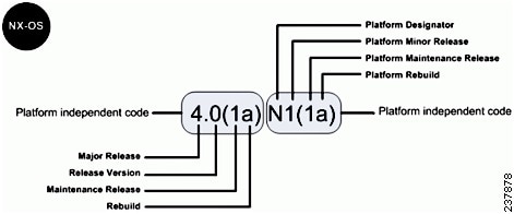
The platform designator is N for the Nexus 5000 Series Switches, E for the Nexus 4000 Series Switches, and S for the Nexus 1000 Series Switches. Applicable features, functions, and fixes in the platform-independent code are present in the platform-dependent release.
Applicable fixes in the Cisco NX-OS Software Release 4.0(1a) are present in the 4.0(1a)N1(1a) release.
Supported Hardware
Cisco Nexus 5000 Series switches are shipped with the Cisco NX-OS software preinstalled. Cisco NX-OS upgrades and downgrades are supported on the hardware listed in the following sections:
Cisco Nexus 5000 Series Switches and Associated Expansion Modules
- Cisco Nexus 5000 2RU Chassis (N5K-C5020P-BF)
- Cisco Nexus 5000 1RU Chassis (N5K-C5010P-BF)
- Cisco Nexus 5000 Series Module 6-port 10 Gigabit Ethernet (N5K-M1600)
- Cisco Nexus 5000 Series Module 4x10GE 4xFC 4/2/1 (N5K-M1404)
- Cisco Nexus 5000 Series Module 6xFC 8/4/2/1 (N5K-M1060)
- Cisco Nexus 5000 Series Module 8xFC 4/2/1 (N5K-M1008)
Upgrade Guidelines
When upgrading system software, follow these guidelines:
You cannot enter configuration mode during an upgrade. You should save, commit, or discard any active configuration sessions before upgrading or downgrading the Cisco NX-OS software image. The active configuration session is deleted without a warning during a reload.
Use the show configuration session summary command to verify that there are no active configuration sessions.
For more information on configuration sessions, see the Cisco Nexus 5000 Series NX-OS System Management Configuration Guide.

Note CLI and SNMP configuration change requests are denied during a in-service software upgrade (ISSU).
- Topology—You should make topology changes such as Spanning Tree Protocol (STP) or Fiber Channel (FC) fabric changes, that affect zoning, Fabric Shortest Path First (FSPF), or FC domains before you perform an upgrade. You should perform module installations or removals only before or after an upgrade.
- Scheduling—You should upgrade when your network is stable and steady. Ensure that everyone who has access to the switch or the network is not configuring the switch or the network during this time. You cannot configure a switch during an upgrade.
- Space—Verify that sufficient space is available in the location where you are copying the images. The internal bootflash requires approximately 200 MB of free space.
- Hardware—Avoid power interruptions during an installation procedure. Power interruptions can corrupt the software image.
- Connectivity to remote servers
Configure the IPv4 address or IPv6 address for the 10/100/1000 BASE-T Ethernet port connection (interface mgmt0). Ensure that the switch has a route to the remote server. The switch and the remote server must be in the same subnetwork if you do not have a router to route traffic between subnets.
- Software image—Ensure that the specified system and kickstart images are compatible with each other as follows:
– If the kickstart image is not specified, the switch uses the current running kickstart image.
– If you specify a different system image, ensure that it is compatible with the running kickstart image.
– Locally—Images are locally available on the switch.
– Remotely—Images are in a remote location and you specify the destination using the remote server parameters and the filename to be used locally.
– Use the ping command to verify connectivity to the remote server.
– Use the dir command to verify the required space is available for the image files to be copied.
– Use the show install all impact command to identify the upgrade impact. This command displays information describing the impact of the upgrade on each Fabric Extender such as the current and upgrade-image versions. This command also displays if the upgrade is disruptive or the reason why the upgrade is disruptive, if the Fabric Extender needs to be rebooted, and the reason why it needs to be rebooted.
Note We recommended that you log in to the console port to begin the upgrade process. In Virtual Port Channel (vPC) topologies, the first upgrade can be performed on either the primary or secondary switch in the topology
Table 1-1 summarizes the terms used in the install all command output to verify module and software image compatibility.
Using the Install All Command
The install all command triggers an ISSU on Cisco Nexus 5000 Series switches and Cisco Nexus 2000 Series Fabric Extenders. The following images are upgraded during the installation:
The install-all command provides the following benefits:
- You can upgrade the Cisco Nexus 5000 Series switches and the Nexus 2000 Series Fabric Extenders using just one command.
- You can receive descriptive information about the intended changes to your system before you continue with the installation. For example, it identifies potential disruptive upgrades.
- You can continue or cancel the upgrade when you see this question (the default is no):
- You can upgrade the Cisco NX-OS software using a non disruptive procedure, when supported.
- The command automatically checks the image integrity, which includes the running kickstart and system images. The command sets the kickstart and system boot variables.
- The command performs a platform validity check to verify that a wrong image is not used.
- Pressing Ctrl +C gracefully ends the install all command. The command sequence completes the update step in progress and returns to the EXEC prompt.
- After entering the install all command, if any step in the sequence fails, the upgrade ends.
- The following message appears to warn you about the impact of upgrading the power sequencer:
Note After a successful power sequence upgrade, you must switch off the power to the system and then power it up.
Upgrading the BIOS and Power Sequencer Images
Changes to BIOS and power sequencers are rare; however, when they occur, they are included in the Cisco NX-OS system image, and the BIOS and power sequencer are upgraded. The summary displayed by the installer during the installation process indicates the current version of the BIOS and power sequencer and the target version.
Note After a successful power sequence upgrade, you must switch off the power to the system and then power it up.
Supported Upgrade and Downgrade Paths for Cisco NX-OS Release 5.2(1)N1(1)
Cisco NX-OS supports in-service software upgrades (ISSUs) that allow a Cisco Nexus 5000 Series switch and any connected FEXs to be upgraded without any traffic disruption (with a brief control plane disruption). A few conditions have to be met for the system to be upgraded via ISSU process – the access layer topology should be ISSU compliant, the current and target versions should be ISSU capable and the network should be stable.
If the conditions required for ISSU are not met or if the user intends to downgrade the software version, the installation process will be disruptive. For example the Cisco Nexus 5000 Series switch and any connected FEX are rebooted, which causes a disruption. If Cisco’s virtual port channel (vPC) is configured on Cisco Nexus 5000 Series switches, it is possible to achieve an upgrade/downgrade with very minimal traffic disruption to servers/hosts.
Table 2 Supported Upgrade and Downgrade Paths for Cisco NX-OS Release 5.2(1)N1(1)
5.0(3)N2(2b)
5.0(3)N2(2a)
5.0(3)N2(2)
5.0(3)N2(1)
5.0(3)N1(1c)
Note Doing a disruptive upgrade between incompatible images will result in loss of certain configurations such as unified ports, Fibre Channel (FC), breakout, and FEX configurations. See CSCul22703 for details.
Note If a supported upgrade or downgrade path is not taken, then certain configurations, especially related to unified ports, Fibre Channel (FC) ports, breakout, and FEX may be lost.
Note If you want to upgrade from a release not listed in the “Current Cisco NX-OS Release” column of Table 2 to 5.2(1)N1(1), then you must first upgrade to a release that is listed in the “Current Cisco NX-OS Release" column and then to 5.2(1)N1(1).
Note If you want to upgrade from a release, that is not listed in the “Current Cisco NX-OS Release” column of Table 2 to the latest Cisco NX-OS release version, then you must first upgrade to a release that is listed in the “Current Cisco NX-OS Release” column and then to the latest release version.
In-Service Software Upgrades
Support for an ISSU on Cisco Nexus 5000 Series switches and Cisco Nexus 2000 Series Fabric Extenders was added with the 4.2(1)N1(1) NX-OS software release.
With a single supervisor system like a Cisco Nexus 5000 Series switch, an ISSU on the Cisco Nexus 5000 Series switch causes the supervisor CPU to reset and load the new software version. The control plane is inactive, but the data plane keeps forwarding packets that lead to an upgrade with no service disruption. After the CPU loads the updated version of Cisco NX-OS, the system restores the control plane to a previous ly known configuration and the runtime state and the data plane are synchronized, because the data plane keeps forwarding packets while the control plane is upgraded, any servers connected to the Cisco Nexus 5000 Series switch access layer should see no traffic disruption.
ISSU and Layer 3
Cisco Nexus 5500 Platform switches support Layer 3 functionality. However, the system cannot be upgraded with the ISSU process (non disruptive upgrade) when Layer 3 is enabled. It is required to unconfigure all Layer 3 features, remove the L3 license, and reload the switch, to be able to upgrade in a nondisruptive way with an ISSU.
ISSU Supported Topologies
This section includes the following topics:
- ISSU Support For Cisco Nexus 2000 Series Fabric Extenders
- ISSU Support for vPC Topologies
- ISSU Support for vPC Topologies with Fabric Extenders
- ISSU Support With Fibre Channel and FCoE Topologies
- Summary of ISSU-Supported Topologies
- Summary of ISSU Unsupported Topologies
- Management Services After an ISSU
- Fiber Channel/FCoE Protocol and Services During an ISSU
- Layer-2 Protocols Impact
- Fiber Channel/FCoE Protocol and Services During an ISSU
ISSU Support For Cisco Nexus 2000 Series Fabric Extenders
Cisco Nexus 2000 Series Fabric Extenders act as line cards to Cisco Nexus 5000 Series switches. The fabric extenders add flexibility to datacenter networking infrastructure by decoupling the physical and logical (Layer 2) topology, reducing the operation expense by lowering management and troubleshooting points, and building a larger layer 2 fabric that is loop-free, with a single layer of switching.
The ISSU process initiated on the Cisco Nexus 5000 Series switches upgrades the entire access layer including the switch and the FEXs that are connected to the switch.
An ISSU first upgrades the switches. Once the switch is operational with the upgraded software, the FEX’s are upgraded. This upgrade of the FEX is done in a rolling fashion, one FEX at a time. This upgrade on the Fabric Extenders is nondisruptive, similar to the upgrade of the switch.
The time required for an ISSU to complete depends on the number of FEX’s that are connected. You should plan a maintenance window with the total upgrade time in mind. The entire upgrade is nondisruptive and is not expected to cause any outage to connected servers.
ISSU Support for vPC Topologies
An ISSU is completely supported when two switches are paired in a vPC configuration. In a vPC configuration, one switch functions as a primary switch and the other functions as a secondary switch .They both run the complete switching control plane, but coordinate forwarding decisions to have optimal forwarding to devices at the other end of the vPC. Additionally, the two devices appear as a single device that supports EtherChannel (static and 802.3ad) and provide simultaneously data forwarding services to that device.
While upgrading devices in a vPC topology,you should start with the switch that is the primary switch. The vPC secondary device should be upgraded after the ISSU process completes successfully on the primary device. The two vPC devices continue their control plane communication during the entire ISSU process (except when the ISSU process resets the CPU of the switch being upgraded).
This example shows how to determine the vPC operational role of the switch:
You can monitor the status of an ISSU on the primary from the primary device command, after the primary switch reloads by using the show install all status command.
Any attempt to initiate an upgrade on the vPC peer switch, when ISSU is progress on the other switch, is blocked.
Note During an upgrade, the configuration on peer switches is locked and the vPC state on vPC peer switches is suspended until the upgrade is complete.
Verifying the vPC Status on a Peer Switch During an Upgrade
To view the vPC status, enter the show vpc command on a peer switch as follows:.
The following message is displayed on the vPC peer switch when an ISSU is started on the other switch:
Viewing System Messages on Peer Switches
A keepalive message such as the following may appear on a peer switch during an upgrade:
Installation status messages such as the following may appear on peer switches as the primary switch is upgraded.
ISSU Support for vPC Topologies with Fabric Extenders
An ISSU is supported in vPC topologies that include FEXs that are connected in dual-homed topologies to a parent switch and when the FEX is in a single-homed topology.
To perform a nondisruptive upgrade, in a vPC environment that has FEXs connected to a switch, perform the following steps:
1. Perform a nondisruptive upgrade on the first switch.
2. Check the status of FEXs on the second switch prior to performing a nondisruptive upgrade on it. If any of the FEXs are in Active-Active (AA) version mismatch state, shut the corresponding NIF ports of the impacted FEXs.
3. Perform a nondisruptive upgrade on the second switch using the install all command.
4. After the upgrade is complete on the second s witch, bring up the ports that were shut in the Step 2.
Note After the upgrade procedure, ensure all the FEX ports are in online state, including the Active-Active version mismatch ports.
ISSU Support With Fibre Channel and FCoE Topologies
ISSUs are supported on access layer switches when Fibre Channel and Fibre Channel over Ethernet (FCoE) is enabled. You must ensure that the FC fabric is stable before initiating an ISSU in this topology.
Summary of ISSU-Supported Topologies
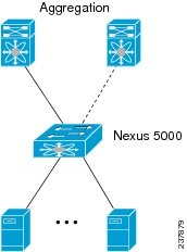
The following figure shows an access switch topology.
Figure 1-2 Access Switch Topology
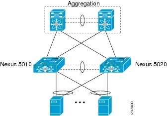
The following figure shows a vPC peering topology.
Figure 1-3 vPC Peering Topology
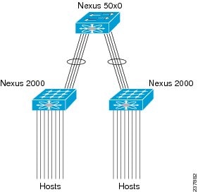
The following figure shows a virtual modular system with static fabric connectivity for FEXs.
Figure 1-4 Virtual Modular System With Static Fabric Connectivity For FEXs

The following figure shows a vertical modular system.
Figure 1-5 Virtual Modular System
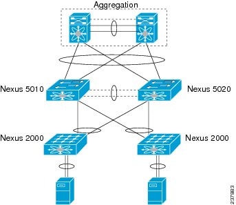
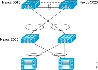
The following figure shows a vPC-peered dual-supervisor virtual modular system with dual-homed FEXs.
Figure 1-6 vPC-Peered Dual-Supervisor Virtual Modular System Dual-Homed FEXs
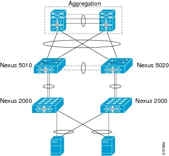
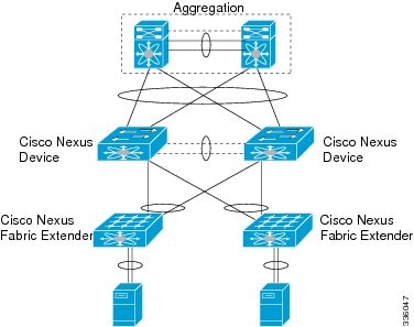
The following figure shows a vPC-peered dual-supervisor virtual modular system with dual-homed and single-homed FEXs.
Figure 1-7 vPC-Peered Dual-Supervisor Virtual Modular System Dual-Homed and Single-Homed FEXs
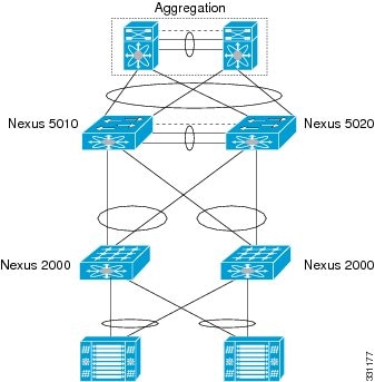
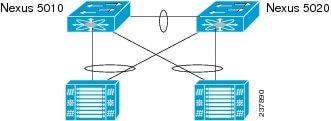
The following figure shows a vPC-peered dual-supervisor virtual modular system with dual-homed FEXs.
Figure 1-8 vPC Peered Dual-Supervisor Virtual Modular System Dual-Homed FEXs
Summary of ISSU Unsupported Topologies
Two important spanning tree-related requirements for a Cisco Nexus 5000 Series switch undergoing an ISSU are as follows. Note that a switch undergoing an ISSU has its control plane inactive while the switch is reset and the new software version is loaded. Not having these restrictions could render the network unstable, if there are any unexpected topology changes:
- STP enabled switches cannot be present downstream to the switch undergoing an ISSU.
- The STP Bridge Assurance feature cannot be configured except on a vPC peer link. Bridge Assurance is enabled by configuring an interface as a spanning-tree port type network.
If the STP conditions are not met, the installation check will indicate that the upgrade would be disruptive. In this case, you can perform an upgrade at a later time after making necessary changes to the topology to meet these conditions or perform a disruptive upgrade.
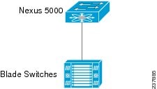
The following figure shows a Cisco Nexus 5000 Series switch that is connected to a blade switch that is running STP.
Figure 1-9 Connection to a Blade Switch that is Running STP
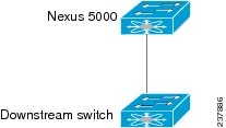
The following figure shows a Cisco Nexus 5000 Series switch that is connected to a downstream switch that is running STP.
Figure 1-10 Connection to a Downstream Switch that is Running STP
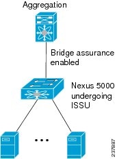
The following figure shows a Cisco Nexus 5000 Series switch that is running Bridge Assurance with another switch.
Figure 1-11 Cisco Nexus 5000 Series Switch Running Bridge Assurance with Another Switch
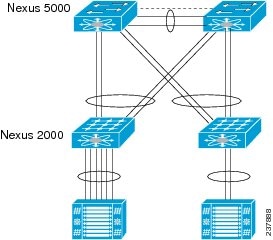
The following figure shows dual-homed FEXs connected to a stub switch.
Figure 1-12 Dual-Homed FEXs Connected to a Stub Switch
The following figure shows a single-homed FEX that is connected to stub switches.
Figure 1-13 Single-Homed FEX Connected to Stub Switches
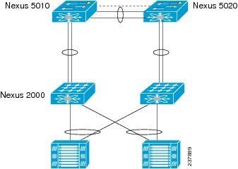
The following figure shows a dual-homed FEX that is connected to stub switches.
Figure 1-14 Dual-Homed FEX Connected to Stub Switches
ISSU Prerequisites
All the upgrade guidelines listed in Cisco NX-OS Upgrade Guidelines section should be strictly adhered to for ISSU to work smoothly. In particular, make sure that the network is stable and no changes are made while an ISSU is in progress. Make sure that you check for feature compatibility between the current running release and the target release.
The following figure shows upgrade restrictions.
Figure 1-15 Upgrade Restrictions
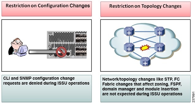
In addition, there are some specific requirements for a non disruptive upgrade (ISSU).
Topology requirements— A Cisco Nexus 5000 Series switch on which an ISSU is being initiated should not be in one of the unsupported topologies listed in the previous figure. No interface should be in a spanning-tree designated forwarding state. Also, bridge assurance should not be configured on any interface of the Cisco Nexus 5000 series switch. vPC peer-link is an exception to these requirements.
Layer 2 requirement— The ISSU process will be aborted if the system has any Link Agregration Control Protocol (LACP) fast timers configured.
FC/FCoE requirements—Check that the topology is stable for an ISSU to work smoothly. The following is a list of things you must check:
Domain Manager—As part of the installation process, domain manager checks if the fabric is in a stable state. If the fabric is not stable, the installation will abort.
CFS—As part of the installation process, CFS checks if any application (ntp,fsm, rcsn, fctime) is locked. If any application is holding a CFS lock, the installation will abort.
Zone Server— The installation process aborts if a zone merge or zone change request is in progress.
FSPF—As part of the upgrade process, Fabric Shortest Path First (FSPF) verifies if the configured interface dead interval is more than 80 seconds; otherwise, installation will abort.
Management Services After an ISSU
Before the switch is reset for an ISSU, inband and management ports are brought down and are brought back up after the ISSU completes. Services that depend on the inband and management ports are impacted during this time.
Fiber Channel/FCoE Protocol and Services During an ISSU
During an ISSU, the control plane is offline for up to 80 seconds. Any state changes in the network during this time are not processed. Depending on the change, the impact may vary. We always recommended that you ensure a stable fabric during an ISSU. See the following table for other ISSU impacts.
Layer-2 Protocols Impact
The following table lists the ISSU impacts to Layer 2 protocols.
Ethernet Interfaces on the Switch and the Fabric Extenders
To avoid link down to link up transitions during the control plane outage time, the laser is turned off for administratively up ports that are operationally down. This situation occurs during the ISSU reboot starting state when the switch and the FEX applications stop communicating with each other. After the ISSU reboot and a stateful restart, the laser is turned back on. This action prevents the link state from transitioning from down to up during an ISSU.
PreInstallation Checks
You should do certain sanity checks to ensure that the system is ready for an ISSU and to understand the impact of ISSU:
- Enter the show incompatibility command to verify that the target image is feature-wise compatible with the current image.
- Enter the show logging level command to ensure that the severity level for all processes is set to 5 or below.
- Enter the show install all impact command to identify the upgrade impact.
- Enter the show fex command to verify that all the FEXs are online.
- Enter the show vpc role command to verify the vPC switch role in a vPC topology.
- Enter the install all command to update to the latest Cisco NX-OS software.
- Review the installer impact analysis and choose to continue.
Note The switch might reload at this time and cause a traffic disruption if the upgrade is not an ISSU.
- Monitor the installation progress.
- Verify the upgrade.
- Enter the show install all status command to verify the status of the installation
The following table lists the show commands that identify the impact or potential problems that may occur when performing an ISSU.
You can also perform the following tasks to identify potential problems before they occur:
- Ensure that you have enough space to store the images on bootflash:
- Display incompatible configurations on the current system that will impact the upgrade version.
Use the show lacp issu-impact command to display if any port or a peer switch is configured in rate fast mode.
Upgrading Procedures
The ISSU process is triggered when you enter the install all command. This section describes the sequence of events that occur when you upgrade a single Cisco Nexus 5000 Series switch or a single Cisco Nexus 5000 Series switch that is connected to one or more FEXs.
Note To use the ISSU process for Release 4.2(1)N1(1) through Release 5.0(2)N2(1a), you must first upgrade to Release 5.1(3)N1(1). After that, use the ISSU process to upgrade to Release 5.2.
The section includes the following topics:
- Installation At-A-Glance
- Copying the Running Configuration from an External Flash Memory Device
- Copying the Startup Configuration from an External Flash Memory Device
- Upgrade Process in a Non-vPC Topology
- Upgrade Process for a vPC Topology on the Primary Switch
- Upgrade Process for a vPC Topology on the Secondary Switch
- Upgrading From Cisco NX-OS Release 5.0(2)N2(1a) and Earlier Releases (Disruptive Upgrade)
- Minimizing the Impact of a Disruptive Upgrade
- Upgrading a Direct vPC or a Single-Homed FEX Access Layer
- Upgrading a Dual-Homed FEX Access Layer
Installation At-A-Glance
The following table shows an overview of the upgrade process.
Copying the Running Configuration from an External Flash Memory Device
You can copy configuration files from an external flash memory device.
Note This procedure applies to the Cisco Nexus 5500 Platform running Cisco NX-OS Release 5.0.2 and later releases.
Insert the external flash memory device into the active supervisor module.
Copying the Startup Configuration from an External Flash Memory Device
You can recover the startup configuration on your Cisco NX-OS device by downloading a new startup configuration file saved on an external flash memory device.
Note This procedure applies to the Cisco Nexus 5000 Platform running Cisco NX-OS Release 5.0.2 and later releases.
Insert the external flash memory device into the active supervisor module.
Upgrade Process in a Non-vPC Topology
The following list summarizes the upgrade process in a non-vPC topology:
1. The install all command triggers the installation upgrade.
2. The compatibility checks display the impact of the upgrade.
3. The installation proceeds or not based on the upgrade impact.
4. The current state is saved.
5. The system unloads and runs the new image.
6. The stateful restart of the system software and application occurs.
7. The installer resumes with the new image.
8. The FEXs are upgraded sequentially.
9. The installation completes.
Upgrade Process for a vPC Topology on the Primary Switch
The following list summarizes the upgrade process on a primary switch in a vPC topology. Steps that differ from a switch upgrade in a non-vPC topology are in bold.
Note In vPC topologies, the two peer switches must be upgraded individually. An upgrade on one peer switch does not automatically update the vPC peer switch.
1. The install all command issued on the vPC primary switch triggers the installation upgrade.
2. The compatibility checks display the impact of the upgrade.
3. The installation proceeds or not based on the upgrade impact.
4. The configuration is locked on both vPC peer switches.
5. The current state is saved.
6. The system unloads and runs the new image.
7. The stateful restart of the system software and application occurs.
8. The installer resumes with the new image.
9. The FEXs are upgraded sequentially.
10. The installation is complete.
When the installation is complete, the vPC primary switch and the FEXs that are connected to the primary switch are upgraded. The single-homed FEXs and the dual-homed FEXs are now running the upgraded software.
Note The dual-homed FEXs are now connected to the primary and secondary switches that are running two different versions of the Cisco NX-OS software. The vPC primary switch is running the upgraded version and the vPC secondary switch is running the original software version. The Cisco NX-OS software has been designed to allow an upgraded dual-home FEX to interoperate with vPC secondary switches running the original version of Cisco NX-OS while the primary switch is running the upgrade version.
Upgrade Process for a vPC Topology on the Secondary Switch
The following list summarizes the upgrade process on a secondary switch in a vPC topology. Steps that differ from a switch upgrade in a non-vPC topology are in bold.
1. The install all command issued on the vPC second switch triggers the installation upgrade.
2. The compatibility checks display the impact of the upgrade.
3. The installation proceeds or not based on the upgrade impact.
4. The current state is saved.
5. The system unloads and runs the new image.
6. The stateful restart of the system software and application occurs.
7. The installer resumes with the new image.
8. The FEXs are upgraded sequentially. The upgrade completes on the single-homed FEXs and a sanity check is performed on the dual-homed FEXs.
Note The dual-homed FEXs were upgraded by the primary switch.
9. The configuration is unlocked on the primary and secondary switches.
Disruptive Installation Process

Caution Doing a disruptive upgrade between incompatible images will result in loss of certain configurations such as unified ports, breakout, and FEX configurations. See CSCul22703 for details.
The following lists conditions where a nondisruptive ISSU might not be possible when upgrading a Cisco Nexus 5000 Series access layer switch:
- The topology and/or features are not ISSU ready. See the section on ISSU prerequisites for more information.
- The current release or target release is lower than 5.0(3)N1(1). An ISSU can work only when both the current and target releases are equal or later than 5.0(3)N1(1).
Note To use the ISSU process for Release 4.2(1)N1(1) through Release 5.0(2)N2(1a), you must first upgrade to Release 5.1(3)N1(1). After that, use the ISSU process to upgrade to Release 5.2(1)N1(1).
- The installation is a downgrade, such as a higher release to a lower release, unless stated otherwise in Upgrade Guidelines section.
- You want to do a disruptive upgrade. See the Forcing an Upgrade section.
Restoring the Configuration
Perform the following steps to restore the configuration if the configurations contain interface breakout or unified port configurations:
1. Save the configuration to bootflash using the command copy running-config bootflash :[ directory/ ] filename.
2. Use the default interface command to restore the default configurations of the breakout interfaces. Example: default interface e1/49/1-4, e2/25/1-4 .
3. Save the running configuration to startup configuration using the copy running-config startup-config command.
4. Perform software migration using the install all command from Cisco NX-OS Release 5.2(1)N1(1) to a lower version. In case of VPC, downgrade the primary switch first and then the secondary switch.
5. After the switch is up, power-off and power-on the module for the interface breakout to be effective. If the breakout is configured on Baseboard module, save the running configuration to startup configuration using the copy running-config startup-config command and then reload the switch again.
6. If breakout is not configured on the Baseboard, then an additional reload is required if running configuration contains hardware profile route resource service-template .
7. After the switch is up (with all the modules), copy the saved configuration from bootflash: <filename> to running-config .
8. Verify if all the interfaces are up and traffic is resumed.
Forcing an Upgrade
You can choose to do a disruptive upgrade if one of the ISSU conditions are not met. One additional reason where you might choose to do a disruptive upgrade is when FEXs are upgraded in a rolling fashion (one FEX at a time), which requires a longer maintenance window. With a disruptive upgrade, all the connected FEXs are upgraded simultaneously, so the maintenance window can be shorter. If you need a shorter maintenance window (with traffic disruption), you can force a disruptive upgrade even if an ISSU can be leveraged. It is important to note the possibility of an outage if you do a disruptive upgrade.
You can also add force at the end of the install all command as follows:
Upgrading From Cisco NX-OS Release 5.0(2)N2(1a) and Earlier Releases (Disruptive Upgrade)
This section describes how to upgrade from Cisco NX-OS Release 5.0(2)N2(1a) and earlier releases. An upgrade from these releases will be disruptive. Upgrading a Cisco Nexus 5000 Series switch also upgrades connected Fabric Extenders.
Note To perform a nondisruptive upgrade from Cisco NX-OS Release 5.0(3)N1(1) and later releases, see the “In-Service Software Upgrades” section. You can upgrade Cisco NX-OS Release 4.2(1)N1(1) through Release 5.0(2)N2(1a) using a two-step ISSU process.
DETAILED STEPS
Step 1 Log in to Cisco.com to access the Software Download Center. To log in to Cisco.com, go to http://www.cisco.com/ and click Log In at the top of the page. Enter your Cisco username and password.
Note Unregistered Cisco.com users cannot access the links provided in this document.
Access the Software Download Center at http://www.cisco.com/cisco/software/navigator.html?a=a&i=rpm . Navigate to the software downloads for Cisco Nexus 5000 Series switches. Links to the download images for the switch are listed.
Step 2 Choose and download the kickstart and system software files to a local server.
Step 3 Verify that the required space is available in the bootflash: directory for the image file(s) to be copied.
We recommend that you keep the kickstart and system image files for at least one previous software release to use if the new image files do not load successfully.
Step 4 (Optional) If you need more space on the bootflash, delete unnecessary files to make space available.
Step 5 Copy the new kickstart and system images to the switch bootflash by using a transfer protocol such as FTP, TFTP, SCP, or SFTP. The examples in this procedure use SCP.
switch# copy scp://user@scpserver.cisco.com/downloads/n5000-uk9.5.2.1.N1.1.bin bootflash:n5000-uk9.5.2.1.N1.1.binStep 6 Display the impact of the upgrade.
Step 7 Install the new images, specifying the new image names that you downloaded in the previous step.
Step 8 Verify that the switch is running the required software release.
Minimizing the Impact of a Disruptive Upgrade
A non-ISSU upgrade is a disruptive upgrade that results in the reload of the Cisco Nexus 5000 Series switch and the Cisco Nexus 2000 Series Fabric Extenders. The reload is a cold reboot that brings down the control plan and the data plane. The reload causes disruptions to the connected servers and hosts. When a vPC is deployed in the access layer, it is possible to minimize the impact of a non-ISSU upgrade. When one of the vPC switches is being reset during the upgrade process, all the server traffic can flow through its vPC peer.
Upgrading a Direct vPC or a Single-Homed FEX Access Layer
The following figures show topologies in which the access layer includes a vPC configuration to hosts or downstream switches.
Figure 1-16 Hosts Directly Connected to vPC Peers
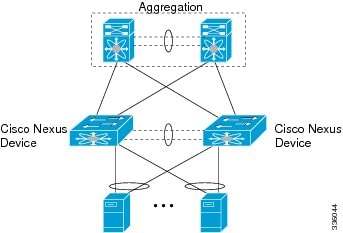
Figure 1-17 vPC Peered Dual-Supervisor Virtual Modular System Dual-Homed FEXs and Singled-Homed FEXs
Figure 1-18 Cisco Nexus 5000 Series Switches Connected To Downstream Switches
To upgrade the access layer without a disruption to hosts, follow these tasks:
- Upgrade the first vPC switch (vPC primary switch). During this upgrade, the switch is reloaded. When the switch is reloaded, the servers or the downstream switch detects a loss of connectivity to the first switch and starts forwarding traffic to the second (vPC secondary) switch.
- Verify that the upgrade of the switch has completed successfully. At the completion of the upgrade, the switch restores vPC peering, connected Nexus 2000 Fabric Extenders and all the links.
- Upgrade the second switch. Repeating the same process on the second switch causes the second switch to reload during the upgrade process. During this reload, the first (upgraded) switch forwards all the traffic to/from servers.
- Verify that the upgrade of the second switch has completed successfully.
Note Flows that are forwarded to a switch during an upgrade on the switch, will failover to the second switch. Also, flows are redistributed when vPC peers are active. The traffic disruption is limited to the time required for the server or host to detect the link-down and link-up events and to redistribute the flows.
Note Upgrading Cisco NX-OS Software by changing the boot-variables and performing a reload is not supported in Cisco Nexus 5000 and 6000 Series Switches. This may result in loss of configuration and forwarding issues.
Upgrading a Dual-Homed FEX Access Layer
A disruptive upgrade causes a switch and connected FEXs to reload. The time required for a FEX to reload is less than the time required for a switch to reload. When hosts are connected to a dual-homed FEX, it is possible to keep the traffic disruption of the hosts to same time as required by FEX to reload (approximately 120 seconds), instead of the time required for an upgrade of the entire access layer.
The following figure shows a dual-homed FEX topology in which the access layer includes a vPC configuration to hosts or downstream switches.
Figure 19 vPC-Peered Dual-Supervisor Virtual Modular System Dual-Homed FEXs
Note The following dual-homed FEX procedure is supported only for an upgrade and not for a downgrade.
Step 1 Configure FEX module pre-provisioning for all the FEXs connected to both the switches (vPC primary and vPC secondary switches).
Upgrade the vPC primary switch with the new image using the install all kickstart image system image command. During the upgrade process, the switch is reloaded. When the switch is reloaded, only singled-homed FEXs connected to the switch are reloaded and dual-homed FEXs are not reloaded. Servers connected to the dual-homed FEXs retain network connectivity through the vPC secondary switch.
Step 2 Verify that the upgrade of the vPC primary switch is completed successfully. At the completion of the upgrade, the vPC primary switch restores vPC peering. However, dual-homed FEXs are connected only to the secondary vPC switch.
Step 3 Reload the dual-homed FEXs using the reload fex command from the vPC secondary switch. Reload the FEXs one-by-one or in a bunch of two or three FEXs. The servers connected to the dual-homed FEXs will lose connectivity.
Step 4 Wait for the FEXs to reload. After the reload, the FEXs connect to the upgraded switch (vPC primary switch).
Step 5 Upgrade the vPC secondary switch with the new image using the install all kickstart image system image command. During the upgrade process, the switch is reloaded. When the switch is reloaded, only singled-homed FEXs connected to the switch are reloaded and dual-homed FEXs are not reloaded.
Step 6 Verify that the upgrade of the vPC secondary switch is completed successfully. At the completion of the upgrade, the vPC secondary switch restores vPC peering. Dual-homed FEXs connect to both the peer switches and start forwarding traffic.
Detailed Steps
Step 1 Log in to Cisco.com to access the Software Download Center. To log in to Cisco.com, go to http://www.cisco.com/ and click Log In at the top of the page. Enter your Cisco username and password.
Note Unregistered Cisco.com users cannot access the links provided in this document.
Access the Software Download Center at http://www.cisco.com/cisco/software/navigator.html?a=a&i=rpm . Navigate to the software downloads for Cisco Nexus devices. Links to the download images for the switch are listed.
Step 2 Choose and download the kickstart and system software files to a local server.
Step 3 Verify that the required space is available in the bootflash: directory for the image file(s) to be copied.
We recommend that you keep the kickstart and system image files for at least one previous software release to use if the new image files do not load successfully.
Step 4 (Optional) If you need more space on the bootflash, delete unnecessary files to make space available.
Step 5 Copy the new kickstart and system images to each switch bootflash by using a transfer protocol such as FTP, TFTP, SCP, or SFTP.
Step 6 Configure FEX Module pre-provisioning for the type of FEX present in the system. Perform this step on both the switches in a vPC pair. For more information on how to configure FEX module pre-provisioning, refer the Cisco Nexus 5000 Series NX-OS System Management Configuration Guide.
This example shows how to select slot 130 and the N2K-C2348UPQ module to pre-provision.
Step 7 Enter the show install all impact command to validate the upgrade process and the components being upgraded.
switch-1# show install all impact kickstart bootflash:n5000-uk9-kickstart.5.2.1.N1.1 system bootflash:n5000-uk9.5.2.1.N1.1Step 8 Enter the install all kickstart image system image command on the vPC primary switch.
switch# install all kickstart bootflash:n5000-uk9-kickstart.5.2.1.N1.1 system bootflash:n5000-uk9.5.2.1.N1.1[# ] 0%2017 Apr 4 11:58:11 switch %$ VDC-1 %$ %SATCTRL-FEX130-2-SATCTRL_IMAGE: FEX130 Image update in progress.2017 Apr 4 11:58:21 switch %$ VDC-1 %$ %SATCTRL-FEX198-2-SATCTRL_IMAGE: FEX198 Image update in progress.[#### ] 15%2017 Apr 4 12:03:41 switch %$ VDC-1 %$ %SATCTRL-FEX198-2-SATCTRL_IMAGE: FEX198 Image update complete. Install pending[###### ] 25%2017 Apr 4 12:05:49 switch %$ VDC-1 %$ %SATCTRL-FEX130-2-SATCTRL_IMAGE: FEX130 Image update complete. Install pending2017 Apr 4 12:06:03 switch %$ VDC-1 %$ %KERN-0-SYSTEM_MSG: [2007269.320144] Shutdown Ports.. - kernel2017 Apr 4 12:06:03 switch %$ VDC-1 %$ %KERN-0-SYSTEM_MSG: [2007269.329300] writing reset reason 49, - kernel2017 Apr 4 12:06:07 switch %$ VDC-1 %$ %VPC-2-PEER_KEEP_ALIVE_RECV_FAIL: In domain 572, VPC peer keep-alive receive has failedINIT: Apr 4 12:06:08 %LIBSYSMGR-3-SIGTERM_FORCE_EXIT Service "patch-installer" (PID 4196) is forced exit.Apr 4 12:06:08 %LIBSYSMGR-3-SIGTERM_FORCE_EXIT Service "__inst_001__ospf" (PID 5442) is forced exit.Apr 4 12:06:08 %LIBSYSMGR-3-SIGTERM_FORCE_EXIT Service "__inst_001__ospfv3" (PID 5535) is forced exit.Apr 4 12:06:08 %LIBSYSMGR-3-SIGTERM_FORCE_EXIT Service "Cert_enroll Daemon" (PID 4225) is forced exit.Apr 4 12:06:15 %ICMPV6-3-MTS_RECV icmpv6 [4324] Error returned from mts_recv(), errno: Interrupted system callx?x?xx??xx???????x????x??????????????x????x???x?????????????xx??????x??x??????xx?x???x???x?xx??x???????????xx?x???x???????x?????x????xx??x???x??????x????????xx?????x????x????x????????x?????xx???x?xx?x????x????xx???x?x?????x??x???x????xx???x?x?????x??x???x????xx???x?x?????x??x???x????xx???x?x?????x?????x????xx???x?x?????x??x???x????xx???x?x?????x??x???x????xx???x?x?????x??x???x????xx???x?x?????x???????x????xx???x?x?????x??x???x????xx???x?x?????x??x???x????xx???x?x?????x??x???x????xx???x?x?????x??x???x????xx???x?x?????x??x???x????xx???x?x?????x???????x????xx???x?x?????x??xxxx?x?x??x?xx?x?x??x?x?x?x?????x????x??x??x?xx?x???xxx?x?xxx??x?xx?xx??xx??xx?x?xx??????????xxxx??x??x?x?xx?xx?xxx??????xx?????x????x?????xxload_plugin: Can't get exclude list from /isan/plugin/0/boot/etc/plugin_exclude.conf (rc 0x40ea0017)2017 Apr 4 12:08:49 switch %$ VDC-1 %$ %SYSLOG-2-SYSTEM_MSG : Syslogs wont be logged into logflash until logflash is online2017 Apr 4 12:08:53 switch %$ VDC-1 %$ %KERN-0-SYSTEM_MSG: [ 13.421467] TCO_TMR val:1023, SMI_EN= 0x42033 NMI_STS_CNT_REG = 0x3d count7 . - kernel2017 Apr 4 12:09:02 switch %$ VDC-1 %$ %DAEMON-2-SYSTEM_MSG: <<%XMLMA-2-XMLMACRIT>> XML master agent: Starting sysmgr handshake. - xmlma[4313]2017 Apr 4 12:09:02 switch %$ VDC-1 %$ %DAEMON-2-SYSTEM_MSG: <<%XMLMA-2-XMLMACRIT>> XML master agent: Done with sysmgr handshake. - xmlma[4313]2017 Apr 4 12:09:57 switch %$ VDC-1 %$ %PFMA-2-PS_FAIL: Power supply 2 failed or shutdown(Serial number POG151850HC)switch login: 2017 Apr 4 12:13:35 switch %$ VDC-1 %$ clis: Enabling feature ospf: and calling licmgr_resgister2017 Apr 4 12:14:36 switch %$ VDC-1 %$ %VPC-2-VPC_SVI_DELAY_RESTORE_TIMER: Delay restore timer will be overwritten to 150 sec when l3 is installed. Old value:(150)2017 Apr 4 12:15:34 switch %$ VDC-1 %$ %PFMA-2-MOD_PWRUP: Module 2 powered up (Serial number FOC18293WRV)During the software upgrade on the primary switch, you can view the FEX upgrade progress using the vPC secondary switch (see the bold output):
switch-2# 2017 Apr 4 11:58:11 switch %$ VDC-1 %$ %SATCTRL-FEX130-2-SATCTRL_IMAGE: FEX130 Image update in progress.2017 Apr 4 11:58:21 switch %$ VDC-1 %$ %SATCTRL-FEX198-2-SATCTRL_IMAGE: FEX198 Image update in progress.2017 Apr 4 12:03:41 switch %$ VDC-1 %$ %SATCTRL-FEX198-2-SATCTRL_IMAGE: FEX198 Image update complete. Install pending2017 Apr 4 12:05:49 switch %$ VDC-1 %$ %SATCTRL-FEX130-2-SATCTRL_IMAGE: FEX130 Image update complete. Install pending
Note The Fabric Extender remains online on the vPC secondary switch while the vPC primary switch is reloaded.
Step 9 Ensure that the upgrade on vPC primary switch is completed. Use the show version command to verify the upgrade on vPC primary switch.
Step 10 On the vPC primary switch after the upgrade, the FEXs connected to the switch are in Active/Active mismatch state.
Step 11 On the vPC secondary switch, reload the first Fabric Extenders (reload only dual-homed FEXs) one at a time and wait for them to come online on the newly upgraded vPC primary switch before proceeding to the next FEX.
2017 Apr 4 13:49:14 switch %$ VDC-1 %$ %ETH_PORT_CHANNEL-5-FOP_CHANGED: port-channel130: first operational port changed from Ethernet2/1 to none2017 Apr 4 13:49:14 switch %$ VDC-1 %$ %ETH_PORT_CHANNEL-5-PORT_DOWN: port-channel130: Ethernet2/1 is down2017 Apr 4 13:49:14 switch %$ VDC-1 %$ %ETH_PORT_CHANNEL-5-PORT_DOWN: port-channel130: port-channel130 is down2017 Apr 4 13:49:14 switch %$ VDC-1 %$ %FEX-5-FEX_PORT_STATUS_NOTI: Uplink-ID 1 of Fex 130 that is connected with Ethernet2/1 changed its status from Active to Disconnected2017 Apr 4 13:49:14 switch %$ VDC-1 %$ %NOHMS-2-NOHMS_ENV_FEX_OFFLINE: FEX-130 Off-line (Serial Number FOC1818R2MF)switch# 2017 Apr 4 13:55:35 switch %ETH_PORT_CHANNEL-5-FOP_CHANGED: port-channel198: first operational port changed from Ethernet2/2 to none2017 Apr 4 13:55:35 switch %FEX-5-FEX_PORT_STATUS_NOTI: Uplink-ID 1 of Fex 198 that is connected with Ethernet2/2 changed its status from Active to Disconnected2017 Apr 4 13:55:35 switch %NOHMS-2-NOHMS_ENV_FEX_OFFLINE: FEX-198 Off-line (Serial Number FOC1910R0R1)
Note Only the vPC primary switch shows that the Fabric Extender is online because the vPC secondary switch does not have the new image. The secondary switch shows the Fabric Extender in Active/Active version mismatch state.
Note Make sure that the first Fabric Extender comes up before reloading the subsequent Fabric Extenders on the vPC secondary switch.
When all the Fabric Extenders are loaded, go to the next step.
To upgrade the vPC secondary switch, follow Step 2 to Step 9.
Step 12 Verify all the FEXs connected to the vPC secondary switch are online. Use the show fex command to view the FEX status.
Note You should do certain sanity checks to ensure that the system is ready for an ISSU and to understand the impact of an ISSU.
Monitoring the Upgrade Status
Table 1-8 lists the show commands that are used to monitor installation upgrades.
The following example shows the output from the show install all status command:
The following example shows the output from the show fex command on two vPC peer switches where FEX 198 and FEX 199 are upgraded:
Downgrading from a Higher Release
Downgrading from Cisco NX-OS Release 5.2(1)N1(1) to any lower version using the install all command is the same as manually setting the boot variables and reloading the switch. Note that the downgrades are disruptive. The ASCII configuration replay for downgrade on Cisco Nexus 5000 Series switches will be enabled. You can use the show incompatibility system command to ensure that there are no feature incompatibilities between the current release and the target release.
Note For FEX configurations, before performing a downgrade, the FEX configurations must be converted to use the FEX pre-provisioning configurations. For pre-provisioning a FEX, use the slot <slot-id> provision model <model-number> command.
After FEX pre-provisioning is done, perform the following steps to restore the configuration if the configurations contain interface breakout or unified port configurations:
1. Save the configuration to bootflash using the command copy running-config bootflash :[ directory/ ] filename.
2. Use the default interface command to restore the default configurations of the breakout interfaces. Example: default interface e1/49/1-4, e2/25/1-4 .
3. Save the running configuration to startup configuration using the copy running-config startup-config command.
4. Perform in-service software downgrade (ISSD) using the install all command from Cisco NX-OS Release 5.2(1)N1(1) to a lower release. In case of vPC, downgrade the primary switch first and then the secondary switch.
5. After the switch is up, power-off and power-on the module for the interface breakout to be effective. If the breakout is configured on Baseboard module, save the running configuration to startup configuration using the copy running-config startup-config command and then reload the switch again.
6. If breakout is not configured on the Baseboard module, then an additional reload is required if running configuration contains hardware profile route resource service-template .
7. After the switch is up (with all the modules), copy the saved configuration from bootflash: <filename> to running-config .
8. Verify if all the interfaces are up and traffic is resumed.
Note Before you downgrade to a specific release, check the release notes for the current release installed on the switch to ensure that your hardware is compatible with the specific release. You must be aware of special caveats before you downgrade the switch software to a Cisco NX-OS 4.0(0)-based release. See the Release Notes for your platform for details.
Troubleshooting ISSUs and Disruptive Installations
Some common causes for ISSU failure are as follows:
- ISSU requirements are not met – bridge assurance is active or the switch is not a leaf node in the STP topology. These problems are described in the commands explained in Pre-ISSU Checks section.
- bootflash: does not have enough space to accept the updated image.
- Specified system and kickstart are not compatible.
- Hardware is installed or removed while the upgrade is in process.
- Any power disruption while an upgrade is in progress.
- The entire path for the remote server location is not specified accurately.
Related Documentation
Documentation for Cisco Nexus 5000 Series Switches and Cisco Nexus 2000 Series Fabric Extenders is available at the following URL:
http://www.cisco.com/c/en/us/support/switches/nexus-5000-series-switches/tsd-products-support-series-home.html
The documentation set includes the following types of documents:
- Licensing Information Guide
- Release Notes
- Installation and Upgrade Guides
- Configuration Guides
- Configuration Examples and TechNotes
- Programming Guides
- Operations Guides
- Error and System Message Guides
- Field Notices
- Security Advisories, Responses and Notices
- Troubleshooting Guide
- Command References
- MIB Reference Guide
Documentation Feedback
To provide technical feedback on this document or to report an error or omission, please send your comments to nexus5k-docfeedback@cisco.com . We appreciate your feedback.
Obtaining Documentation and Submitting a Service Request
For information on obtaining documentation, using the Cisco Bug Search Tool (BST), submitting a service request, and gathering additional information, see What’s New in Cisco Product Documentation .
To receive new and revised Cisco technical content directly to your desktop, you can subscribe to the What’s New in Cisco Product Documentation RSS feed . The RSS feeds are a free service.
 Feedback
Contact Cisco
- Open a Support Case

- (Requires a Cisco Service Contract)