Feedback
Table Of Contents
FabricPath Versus Classical Ethernet Networks
Guidelines and Limitations of FabricPath
Verifying the FabricPath Configuration
Migrating to a vPC+ Environment
Using FabricPath
This chapter describes how to configure FabricPath on the Cisco Nexus 5500 Series devices.
This chapter includes the following sections:
•
FabricPath Versus Classical Ethernet Networks
•
•
•
Information About FabricPath
Note
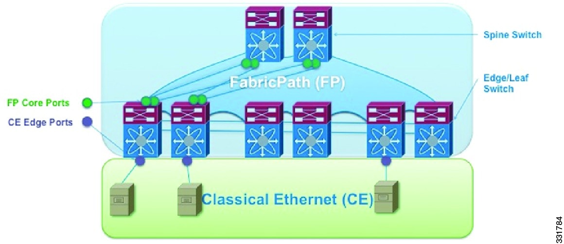
FabricPath switching allows multipath networking at the Layer 2 level without using the Spanning Tree Protocol (STP) see Figure 1-1. The FabricPath network still delivers packets on a best-effort basis, which is similar to the Classical Ethernet (CE) network, but the FabricPath network can use multiple paths for Layer 2 traffic. In a FabricPath network, you do not run STP with its blocking ports. Instead, you use FabricPath across datacenters, some of which have only Layer 2 connectivity with no need for Layer 3 connectivity and IP configurations.
FabricPath encapsulation facilitates MAC address mobility and server virtualization, which means that you can physically move the Layer 2 node but retain the same MAC address and VLAN association for the virtual machine. FabricPath also allows LAN extensions across datacenters at Layer 2, which is useful in disaster recovery operations, and clustering applications such as databases.
Finally, FabricPath is useful in high-performance, low-latency computing. With FabricPath, you use the Layer 2 Intermediate System-to-Intermediate System (IS-IS) protocol for a single control plane that functions for unicast, broadcast, and multicast packets. There is no need to run STP because the domain is purely Layer 2. This FabricPath Layer 2 IS-IS is a separate process from Layer 3 IS-IS.
Figure 1-1 FabricPath Topology Overview
FabricPath Versus Classical Ethernet Networks
FabricPath and CE networks use two different protocols: FabricPath networks use Intermediate System-to-Intermediate System (ISIS) and CE networks use STP to construct a forwarding topology. In both networks, broadcast and unknown unicast traffic are flooded along a loop-free computed graph. However, because two different protocols govern the forwarding graph, a mechanism is needed to control the interaction between the two clouds when FabricPath and CE networks are interconnected forming a physical loop.
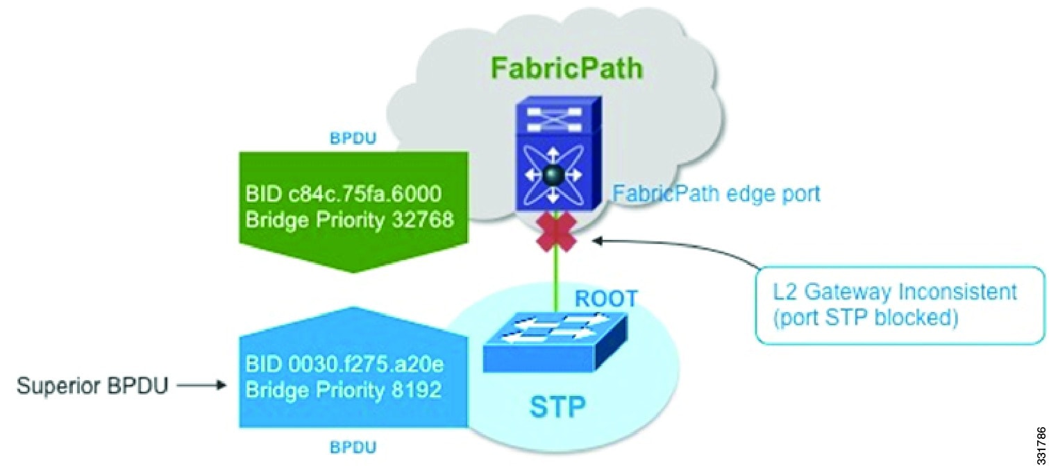
STP bridge protocol data units (BPDUs) are not carried through the FabricPath network. CE interfaces continue to run STP and exchange BDPUs see Figure 1-2.
Layer 2 Gateway Spanning Tree Protocol (L2G-STP) builds a loop-free tree topology. However, it has some limitations. One limitation is that the STP root must always (virtually) be in the FabricPath cloud. For example, it is not possible to have two FabricPath networks connected through a CE cloud. A bridge ID for STP consists of a MAC address and bridge priority. When running in FabricPath mode, the system automatically assigns the edge devices with the MAC address c84c.75fa.6000 from a pool of reserved MAC addresses. As a result, each device has the same MAC address used for the Bridge ID.
Figure 1-2 CE and FabricPath Example
The devices that are in both the FabricPath domain and CE domain are considered to be edge devices or gateway devices. Edge ports have a FabricPath root guard-like function enabled implicitly. If a superior BPDU is received on an edge port, the port is placed in the Layer 2 Gateway inconsistent state until the condition is cleared.
%STP-2-L2GW_BACKBONE_BLOCK: L2 Gateway Backbone port inconsistency blocking port
port-channel100 on VLAN0010.
As a best practice, you should configure all edge devices with the lowest STP priority of all devices in the STP domain to which they are attached. By setting all of the edge devices to be the root bridge, the entire FabricPath domain looks like one virtual bridge to the CE domain. The same recommendation applies to a virtual port channel+ (vPC+) domain; you must configure each device (primary and secondary) as the root.
You configure all FabricPath edge devices by manually setting the bridge priority lower than any STP bridge or by entering these commands.
sw7-vpc(config)# spanning-tree vlan <x> root primary
sw7-vpc(config)# spanning-tree vlan 1-50 root primary
To have a loop-free topology for the CE/FabricPath hybrid network, the FabricPath network automatically displays as a single bridge to all connected CE devices. The STP domains do not cross into the FabricPath network. If multiple STP domains are defined, BPDUs and topology change notifications (TCNs) are localized to the domain. If a connected STP domain is multihomed to the FabricPath domain, a TCN must be able to reach to all devices in the STP domain through the FabricPath domain. As a result, the TCN is sent to the FabricPath domain through the IS-IS protocol data unit (PDU) by default.
vPC+ Environment Migration
The virtual port channel (vPC) feature was introduced on the Cisco Nexus 5000 Series platforms to provide two active paths, to eliminate the need to run the STP protocol, and to have Active-Active redundancy. vPCs are mainly used for servers that can do port channeling as well as connect to Cisco Nexus 2000 Fabric Extenders. vPCs are deployed in the CE domain. When you migrate to a FabricPath network, devices evolve from a vPC to a vPC+ design.
The vPC+ feature was introduced to allow interoperability between FabricPath and vPCs. The functionality and behavior of a vPC+ and a vPC is identical. The same rules apply in both technologies. That is, both require peer link and peer keepalive messages, the configurations must match between the vPC peers, and consistency checks still take place. In a vPC+ domain, a unique FabricPath switch ID is configured and the peer link is configured as a FabricPath core port. This FabricPath switch ID under the vPC+ domain is called the Emulated switch ID. The Emulated switch ID must be the same between the two peers and must be unique per vPC+.
The benefits of using a vPC+ at the edge of a domain are as follows:
•
•
•
•
•
Note
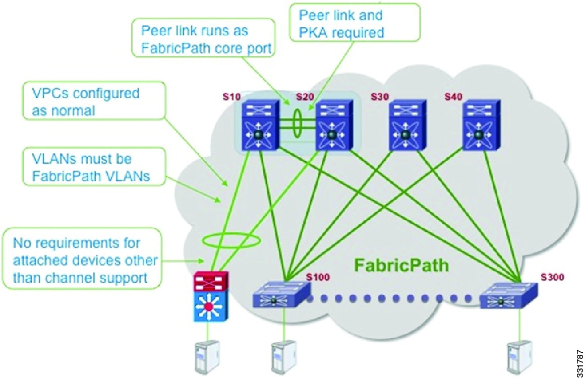
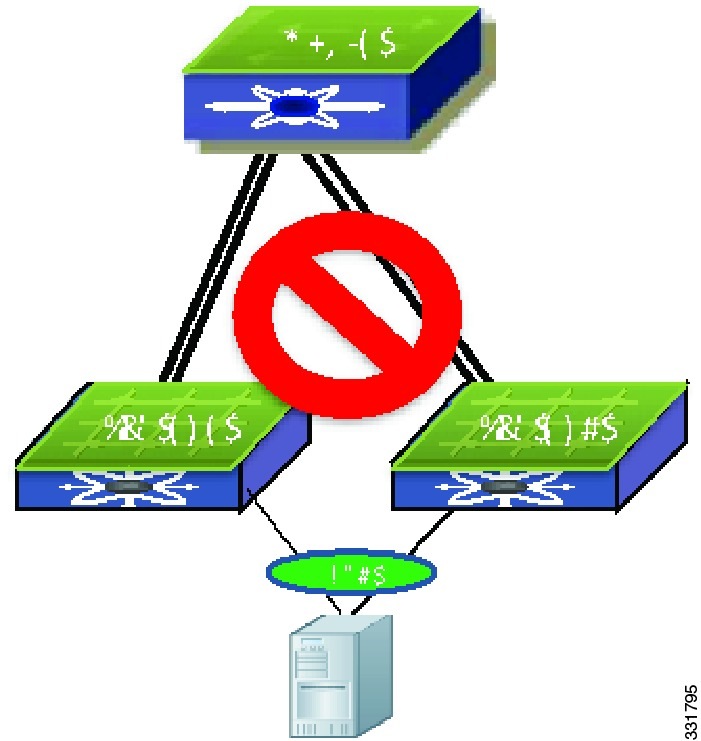
A device can be part of a VPC domain or VPC+ domain, but not both domains. When the peer link is a FabricPath core port, all VLANs that traverse the peer link must be FabricPath VLANs see Figure 1-3.
Figure 1-3 FabricPath Migration Example
FabricPath Link Metrics
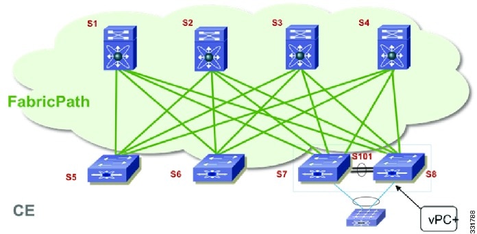
This example shows how to display the FabricPath device ID table. A device's switch ID is shown in addition to the emulated switch ID. The same system ID is displayed twice for each device: one is associated with the switch ID and one is associated with the emulated switch ID.
sw7-vpc# show fabricpath switch idFABRICPATH SWITCH-ID TABLELegend: '*' - this system===================================================================SWITCH-ID SYSTEM-ID FLAGS STATE STATIC EMULATED--------------------------------------+----------------+------------+-----------+--------- -----------1 0022.5579.b1c1 Primary Confirmed Yes No2 0022.5579.b1c2 Primary Confirmed Yes No3 001b.54c2.7f41 Primary Confirmed Yes No4 001b.54c2.7f42 Primary Confirmed Yes No5 0005.73b1.f0c1 Primary Confirmed Yes No*6 0005.73af.08bc Primary Confirmed Yes No7 0005.73b2.0fbc Primary Confirmed Yes No8 0005.73af.0ebc Primary Confirmed Yes No101 0005.73af.0ebc Primary Confirmed No Yes101 0005.73b2.0fbc Primary Confirmed No YesAfter the peer link has been configured with switchport mode fabricpath, it becomes part of the FabricPath topology see Figure 1-4. After a link is detected in a FabricPath topology, the metric of the link is verified and used towards the unicast routing table and the calculation of trees for multidestination traffic. To take advantage of the equal cost multipath (ECMP) paths that are available from edge to spine in the FabricPath topology, we recommend that you increase the IS-IS metric of the peer link to be lower so that it is not added as part of the multidestination tree.
The preferred path to any switch ID is calculated based on the metric to any given destination. The metric is as follows:
•
•
•
Figure 1-4 FabricPath Preferred Paths
You must verify the metric of the links.
This example shows how to display the FabricPath interface information:
sw7-vpc# show fabricpath isis interface briefFabricpath IS-IS domain: defaultInterface Type Idx State Circuit MTU Metric Priority Adjs/AdjsUp--------------------------------------------------------------------------------port-channel1 P2P 2 Up/Ready 0x01/L1 1500 20 64 1/1Ethernet1/7 P2P 4 Up/Ready 0x01/L1 1500 40 64 1/1Ethernet1/8 P2P 1 Up/Ready 0x01/L1 1500 40 64 1/1Ethernet1/9 P2P 3 Up/Ready 0x01/L1 1500 40 64 1/1Because the peer link is a port channel, the metric will be the lowest cost. As a best practice, you should increase the metric so it is higher than the rest of the ECMP links that are part of the FabricPath cloud.
This example shows how to display the FabricPath metric:
sw7-vpc(config-if)# fabricpath isis metric 100sw7-vpc(config-if)# show fabricpath isis interface briefFabricpath IS-IS domain: defaultInterface Type Idx State Circuit MTU Metric Priority Adjs/AdjsUp--------------------------------------------------------------------------------port-channel1 P2P 2 Up/Ready 0x01/L1 1500 100 64 1/1Ethernet1/7 P2P 4 Up/Ready 0x01/L1 1500 40 64 1/1Ethernet1/8 P2P 1 Up/Ready 0x01/L1 1500 40 64 1/1Ethernet1/9 P2P 3 Up/Ready 0x01/L1 1500 40 64 1/1FabricPath Switch IDs
When FabricPath is enabled globally, each device is atomatically assigned with a switch ID (12 bits) You have the option to manually configure the switch ID, but you must ensure all devices in the FabricPath domain have unique values. The switch ID is encoded in the outer MAC addresses of the FabricPath MAC-in-MAC frames.
The Dynamic Resource Allocation Protocol (DRAP) automatically assigns a switch ID and ensures that no duplicate IDs exist in the FabricPath domain. The FabricPath network automatically detects conflicting switch IDs and prevents the data path initialization on the FabricPath interface. As a best practice, we recommend that you manually set the switch IDs.
The emulated switch ID is used in a VPC+ to identify the VPC+ bundle. The emulated switch ID must be unique within each VPC+ virtual switch domain. In a vPC+ domain, three switch ID's will be used—one unique switch ID for each vPC peer and one emulated switch ID that is common between both vPC peers.
This example shows how to display and manually configure the switch ID:
sw5# show fabricpath switch-idFABRICPATH SWITCH-ID TABLELegend: '*' - this system=========================================================================SWITCH-ID SYSTEM-ID FLAGS STATE STATIC EMULATED----------+----------------+------------+-----------+--------------------*3428 0005.73b1.f0c1 Primary Confirmed No NoConversational MAC Learning
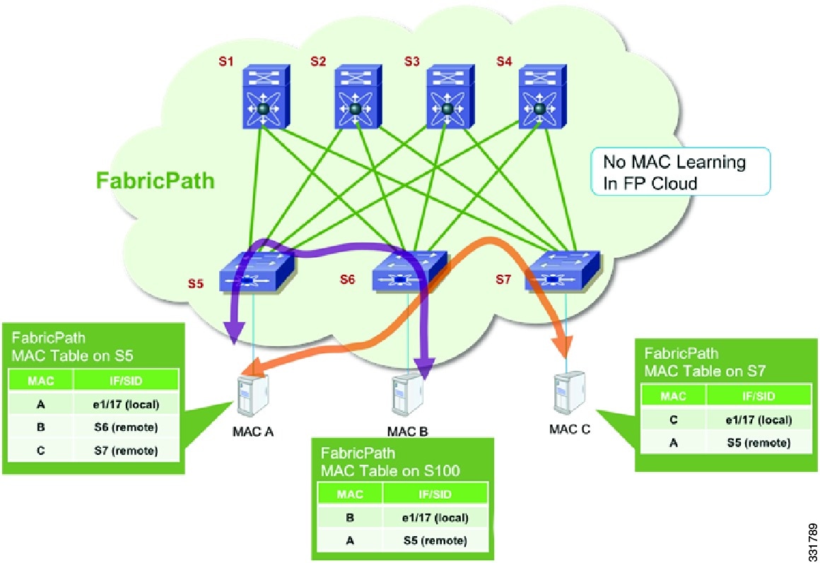
In conversational MAC learning the device learns MAC addresses only if there is an active conversation between a local MAC and a remote MAC (bidirectional traffic) see Figure 1-5. By default, conversational MAC learning is enabled for all FabricPath VLANs. All CE VLANs learn MAC addresses the traditional (CE) way. The default MAC address aging times for both CE and FabricPath VLANs is 300 seconds. If Layer 3 is enabled, the ARP aging timer by default is 1500 seconds. When Layer 3 is enabled, you should set the MAC address aging timer to a higher value than the ARP table to avoid any unnecessary flooding.
Figure 1-5 MAC Address Learning with FabricPath
Note
This example shows how to display the dynamic MAC address table for switches S5 through S7:
S5:S5# show mac address-table dynamicLegend:* - primary entry, G - Gateway MAC, (R) - Routed MAC, O - Overlay MACage - seconds since last seen,+ - primary entry using vPC Peer-LinkVLAN MAC Address Type age Secure NTFY Ports/SWID.SSID.LID---------+-----------------+--------+---------+------+----+------------------5 0000.0000.000c dynamic 0 F F 1:0:75 0000.0000.000a dynamic 0 F F Eth1/175 0000.0000.000b dynamic 10 F F 1:0:6S6:S6# show mac address-table dynamicLegend:* - primary entry, G - Gateway MAC, (R) - Routed MAC, O - Overlay MACage - seconds since last seen,+ - primary entry using vPC Peer-LinkVLAN MAC Address Type age Secure NTFY Ports/SWID.SSID.LID---------+-----------------+--------+---------+------+----+------------------5 0000.0000.000a dynamic 0 F F 1:0:55 0000.0000.000b dynamic 0 F F Eth1/17S7:S7# show mac address-table dynamicLegend:* - primary entry, G - Gateway MAC, (R) - Routed MAC, O - Overlay MACage - seconds since last seen,+ - primary entry using vPC Peer-LinkVLAN MAC Address Type age Secure NTFY Ports/SWID.SSID.LID---------+-----------------+--------+---------+------+----+------------------5 0000.0000.000c dynamic 0 F F Eth1/175 0000.0000.000a dynamic 0 F F 1:0:5Guidelines and Limitations of FabricPath
FabricPath has the following configuration guidelines and limitations:
•
•
•
•
Note
•
•
For a complete list of ISSU guidelines, see the Cisco Nexus 5000 Series NX-OS Software Upgrade and Downgrade Guide, Release 4.2(1)N1(1).
CE and FabricPath VLANs
The CE VLANs carry traffic from the CE hosts to the FabricPath interfaces, and the FabricPath VLANs carry traffic throughout the FabricPath topology. Only the active FabricPath VLANs that are configured on a device are advertised as part of the topology in the Layer 2 IS-IS messages. The device automatically assigns all FabricPath interfaces and FabricPath VLANs to the default topology (Topology 0). Therefore, no additional configuration is required. If a VLAN is a CE VLAN only, it cannot traverse the FabricPath cloud. In order for traffic to transit across the FabricPath cloud, you must specify the VLAN as a FabricPath VLAN.
When configuring a port to be a FabricPath port, enter the switchport mode fabricpath command to put the interface in FabricPath mode and forward all FabricPath VLANs. With FabricPath, you do not need to enter the switchport trunk allowed vlan command. All of the VLANs that are defined you entered the mode fabricpath command are automatically carried on interfaces when you entered the switchport mode fabricpath command. Because all FabricPath VLANs forward on a FabricPath port, you do not need to use the switchport trunk allow vlan x command.
You must exit the VLAN configuration mode for the VLAN mode change to take effect. When running a vPC+, the peer link is configured as a FabricPath core interface. To forward the VLANs downstream on a vPC, you must configure them as FabricPath VLANs and they must be reachable across the peer link.
This example shows how to display the configuration of the FabricPath VLANs:
sw7-vpc# show vpcLegend:(*) - local vPC is down, forwarding via vPC peer-linkvPC domain id : 100vPC+ switch id : 101Peer status : peer adjacency formed okvPC keep-alive status : peer is alivevPC fabricpath status : peer is reachable through fabricpathConfiguration consistency status: successPer-vlan consistency status : successType-2 consistency status : successvPC role : secondary, operational primaryNumber of vPCs configured : 2Peer Gateway : DisabledDual-active excluded VLANs : -Graceful Consistency Check : EnabledvPC Peer-link status---------------------------------------------------------------------id Port Status Active vlans-- ---- ------ --------------------------------------------------1 Po1 up 5vPC status---------------------------------------------------------------------------id Port Status Consistency Reason Active vlans vPC+ Attrib-- ---------- ------ ----------- ------ ------------ -----------111 Po111 up success success - DF: PartialTrees
An Ethernet domain, always have two kinds of traffic, unicast traffic and multidestination traffic. In a FabricPath topology, unicast traffic occurs when the traffic is sent to another host (1:1), and the source and destination are known. For unicast traffic, FabricPath uses the routing table to identify the next hop. If there is one best hop, the protocol chooses the individual link. If there is equal cost multipathing (ECMP), the unicast traffic is load balanced across the core interfaces.
In the current release of FabricPath, up to 16 equal cost paths are possible. The default load-balancing scheme for ECMP is a mixed mode (Layer 3 and Layer 4 ports).
This example shows how to display the FabricPath load-balancing configuration:
sw5# show fabricpath load-balanceECMP load-balancing configuration:L3/L4 Preference: MixedHash Control: SymmetricUse VLAN: TRUEYou can modify the variables by using the fabricpath load-balance unicast command.
This example shows how to configure all of the arguments that are available with this command:
sw5(config)# fabricpath load-balance unicast ?<CR>destination Include destination parametersinclude-vlan Use vlanlayer3 Only Layer-3 parameters consideredlayer4 Only Layer-4 parameters consideredmixed Mix of Layer-3 and Layer-4 parameters (default)source Include source parameterssource-destination Include source and destination parametersFabricPath introduces a loop-free broadcast functionality that carries broadcast, unknown unicast, and multicast packets (also known as multidestination traffic). For each broadcast, unknown unicast, and multicast traffic flow, the device chooses the forwarding path from multiple system-created paths or trees.
The device creates two trees to forward the multidestination traffic for each topology. Each tree is identified in the FabricPath network by a unique value or FTag. For the FabricPath network, the device creates Tree 1 (FTag1) that carries broadcast traffic, unknown unicast traffic, and multicast traffic through the FabricPath network. The swtich also creates a second tree, Tree 2 (FTag 2). All of the multicast traffic flows are load balanced across these two trees for each flow.
Within the FabricPath network, the swtich elects a root node that becomes the root for the broadcast tree. That node also identifies another bridge to become the root for the second multidestination tree, which load balances the multicast traffic. In a unicast-only environment, Tree 1 or FTag1 is always used and is seen in all show commands.
The FabricPath network elects a single root device for the first (broadcast) multidestination tree in the topology. All FabricPath devices announce their root priority in the Router Capability TLV. The device with the highest priority value becomes the root for the tree. In the event of a tie, the FabricPath network chooses the device with the highest system ID, and if there is still a tie, then it uses the device with the highest switch ID. The broadcast root determines the roots of any additional multicast trees and announces them in the Router Capability TLV. Multicast roots spread among available devices to balance the load. The selection is based on the same criteria as described above.
As a best practice, we recommended that you manually define the spine devices that are the root of each tree.
Note
This example shows how to configuration of two spine devices at the root of two trees:
Spine 1:fabricpath domain defaultroot-priority 255Spine 2:fabricpath domain defaultroot-priority 254This example shows how to display the multidestination trees for ftag 1 and 2:
spine# show fabricpath isis topology summaryFabricpath IS-IS domain: default FabricPath IS-IS Topology SummaryMT-0Configured interfaces: Ethernet7/1 Ethernet7/2 Ethernet7/3 Ethernet7/4Number of trees: 2Tree id: 1, ftag: 1, root system: 0022.5579.b1c1, 1Tree id: 2, ftag: 2, root system: 0022.5579.b1c2, 2spine# show fabricpath isis trees multidestination 1Fabricpath IS-IS domain: defaultNote: The metric mentioned for multidestination tree is from the root of that tree to that switch-idMT-0Topology 0, Tree 1, Swid routing table2, L1via Ethernet7/4, metric 403, L1via Ethernet7/1, metric 804, L1via Ethernet7/1, metric 805, L1via Ethernet7/2, metric 406, L1via Ethernet7/1, metric 407, L1via Ethernet7/3, metric 408, L1via Ethernet7/3, metric 60101, L1via Ethernet7/3, metric 60Enabling FabricPath
BEFORE YOU BEGIN
•
•
•
PROCEDURE
Step 1
sw7-vpc(config)# install license bootflash:///enhanced_layer2_pkg.licStep 2
sw7-vpc(config)# install feature-set fabricpathStep 3
Note
sw5(config)# vlan 5-20sw5(config-vlan)# mode fabricpathsw5(config-vlan)# exitStep 4
sw5(config)# int ether 1/8-10sw5(config-if-range)# switchport mode fabricpathFigure 1-6 FabricPath Topology Example
Verifying the FabricPath Configuration
PROCEDURE
Step 1
Step 2
sw5# show vlan id 5VLAN Name Status Ports---- -------------------------------- --------- -------------------------------5 VLAN0005 active Po101, Eth1/5, Eth1/6, Eth1/7Eth1/8, Eth1/9VLAN Type Vlan-mode---- ----- ----------5 enet FABRICPATHStep 3
sw5# show fabricpath isis adjacencyFabricpath IS-IS domain: default Fabricpath IS-IS adjacency database:System ID SNPA Level State Hold Time Interfacevveerapp-7k3 N/A 1 UP 00:00:31 Ethernet1/7vveerapp-7k4 N/A 1 UP 00:00:26 Ethernet1/8vveerapp-7k1 N/A 1 UP 00:00:31 Ethernet1/9vveerapp-7k2 N/A 1 UP 00:00:32 Ethernet1/10
Migrating to a vPC+ Environment
BEFORE YOU BEGIN
Install the FabricPath feature.
PROCEDURE
Step 1
sw5# vpc domain 100peer-keepalive destination 172.25.204.86 source 172.25.204.85fabricpath switch-id 101
Note
Step 2
sw5# vlan <range>mode fabricpathStep 3
sw5# interface port-channel1switchport mode fabricpathvpc peer-link
Note
sw7-vpc(config-vpc-domain)# fabricpath switch-id 101
Configuring fabricpath switch id will flap vPCs. Continue (yes/no)? [no] yes