Feedback
Table Of Contents
Information about the Adapter-FEX
Virtual Ethernet Interfaces, vNICs, and Channel Number
Cisco Nexus 5500 Adapter-FEX Topologies
Switch with Adapter-FEX Topologies
Active-Standby Adapter-FEX Topologies
Removing a Server with a Server Network Adapter
Relocating a Server to a Different Physical Interface
Relocating a Server Network Adapter to a Different Server
Servers with Server Network Adapter Topology Configuration Examples
Configuring the Adapter-FEX on the Device
Configuring the Adapter-FEX on the Adapter
Configuring vNICs on the Adapter
Initializing the Server Network Adapter
Dual-Homed FEX Topology Configuration Examples
Active-Standby Server Network Adapter Topology Configuration Examples
Adapter-FEX Initialization with Active-Standby Uplinks in vPC Topology
Adapter-FEX Initialization with Active-Standby Uplinks Dual-Homed FEXs
Configuring Virtual Ethernet Interfaces
Creating Virtual Ethernet Interfaces Automatically
Configuring Virtual Ethernet Interfaces Manually
Configuration Conflicts Between the Switch and Server Network Adapter
Configuring the Adapter-FEX
This chapter describes how to configure the Cisco Nexus 5000 Series Adapter-FEX.
This chapter includes the following sections:
•
Information about the Adapter-FEX
•
•
Information about the Adapter-FEX
The Cisco Nexus 5000 Series platform introduces virtualization of interfaces as part of the Fibre Channel over Ethernet (FCoE) deployment where a single Ethernet interface is virtualized into a Fibre Channel interface and an Ethernet interface. This consolidation allows both Ethernet and Fibre Channel traffic to use the same link.
The Cisco Fabric Extender Link (FEXLink) architecture enhanced this concept by virtualizing multiple Cisco Nexus 2000 Series Fabric Extender (FEX) host/server interfaces over a few fabric uplinks that connect to the parent device (Cisco Nexus 5000 Series device with or without a Cisco Nexus 2000 Series Fabric Extender).
The Cisco NX-OS Adapter-FEX provides the advantages of the FEXLink architecture with that of a server I/O virtualization to create multiple virtual interfaces over a single Ethernet interface to allow the deployment of a dual port NIC on the server and to configure more than two virtual interfaces that the server sees as a regular Ethernet interface. This approach reduces the power and cooling costs and number of network ports required in the data center.
Note
Virtual Ethernet Interfaces, vNICs, and Channel Number
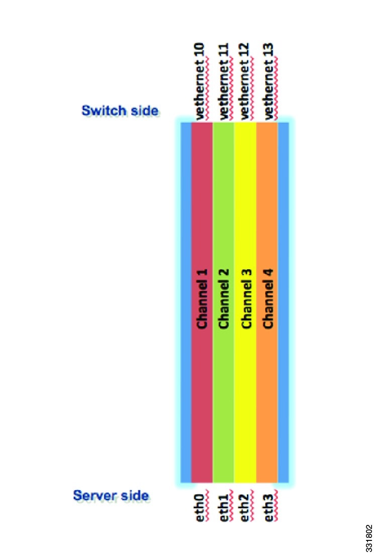
The Adapter-FEX uses a mechanism to divide a single physical link into multiple virtual links or channels see Figure 3-1. Each channel is identified by a unique channel number and its scope is limited to the physical link.
The physical link connects a port on a server network adapter with an Ethernet port on the device, which allows the channel to connect a virtual network interface card (vNIC) on the server with a virtual Ethernet interface on the device.
Packets on each channel are tagged with a virtual network tag (VNTag) with a specific source virtual interface identifier (VIF). The VIF allows the receiver to identify which channel that the source transmit is using, to the packet.
Figure 3-1 Multiple Virtual Links
Supported Platforms
At the access layer, the Adapter-FEX requires a FEX-enabled adapter on a server that connects to a parent device that supports virtualization of interfaces. The Adapter-FEX is supported on the following platforms:
•
•
Note
Note
Cisco Nexus 5500 Adapter-FEX Topologies
This section lists the topologies that are supported and used in the examples described in this document.
Switch with Adapter-FEX Topologies
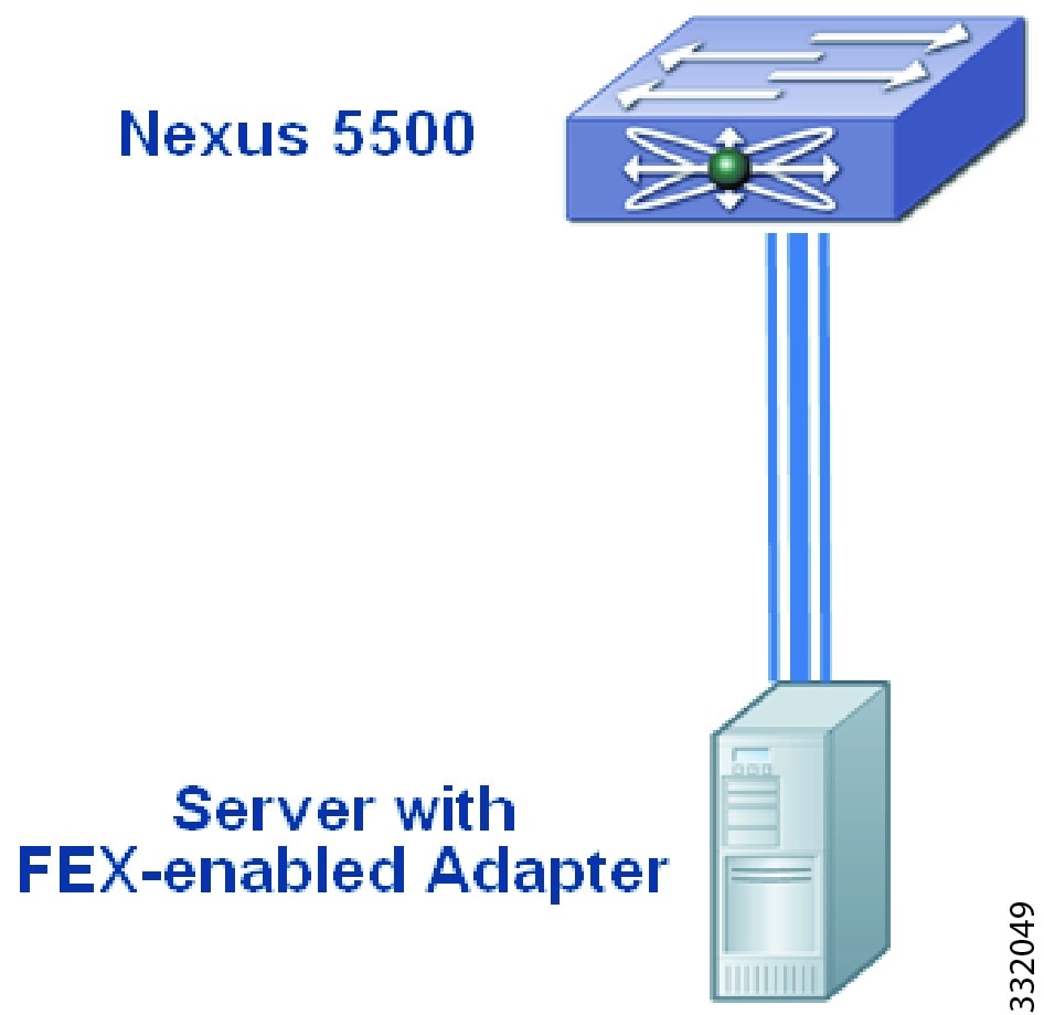
Figure 3-2 shows the topology of a server network adapter that is connected to a Cisco Nexus 5500 Series device.
Figure 3-2 Adapter-FEX-Enabled Server Connected to a Cisco Nexus 5000 Series Device
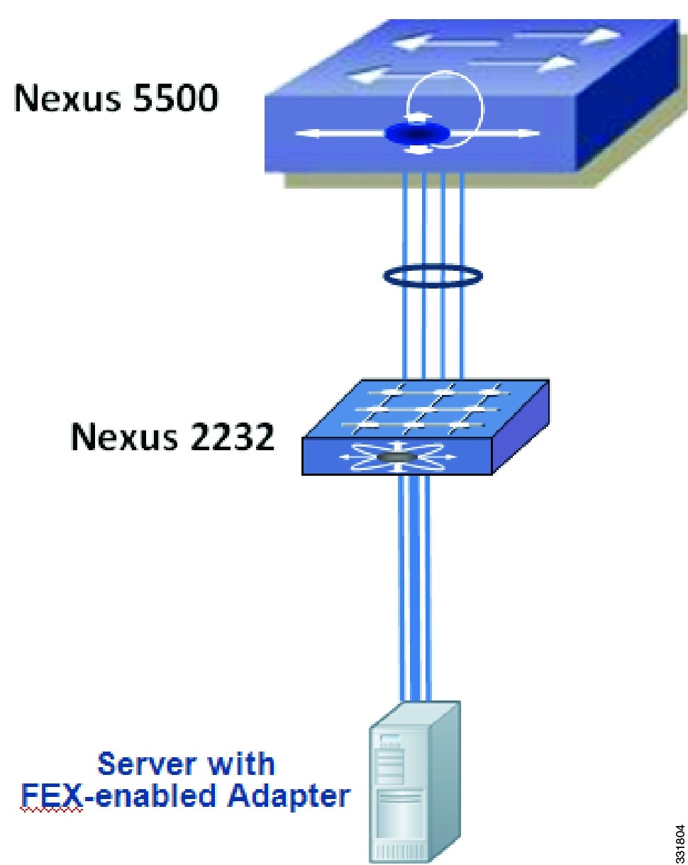
Figure 3-3 shows the topology of a server network adapter connected to a Cisco Nexus 2000 Series Fabric Extender that is connected to a parent Cisco Nexus 5500 Series device.
Figure 3-3 Adapter-FEX-Enabled Server Connected to a Cisco Nexus 2000 Series Fabric Extender
Dual-Homed FEX Topologies
Figure 3-4 shows a server network adapter connected to a Cisco Nexus 2000 Series Fabric Extender that is connected to two peer Cisco Nexus 5500 Series devices in a virtual port channel (vPC) topology.
Figure 3-4 Adapter-FEX-Enabled Server Connected to a Dual-Homed FEX in a vPC Topology
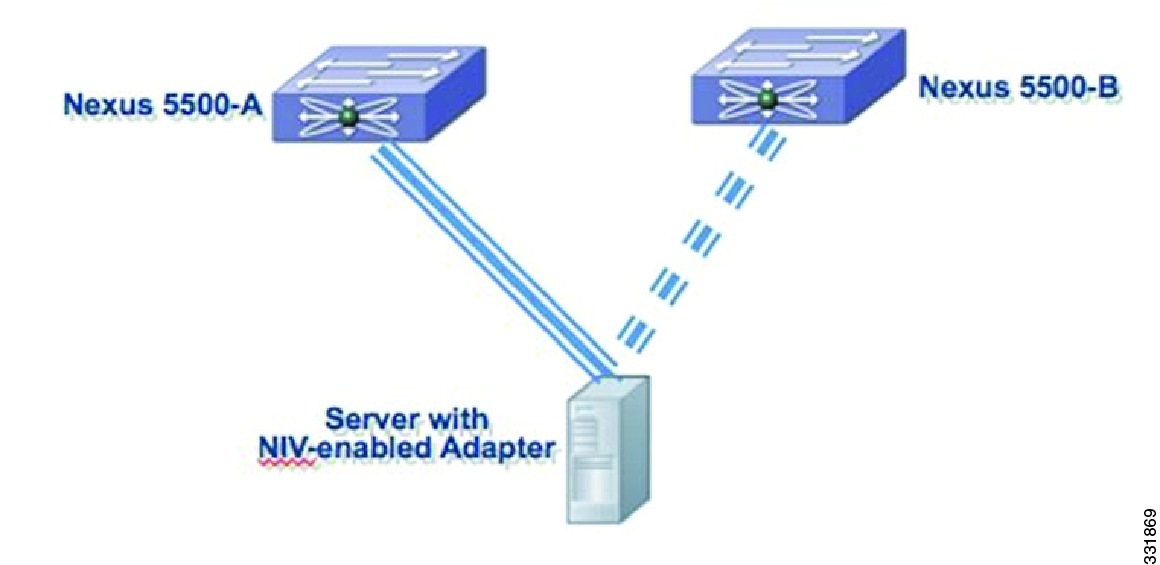
Active-Standby Adapter-FEX Topologies
Adapters that support active-standby uplinks support the following additional topologies.
Note
Note
Figure 3-5 shows a server network adapter connected to the Cisco Nexus 5500-A device by an active uplink interface and to the Cisco Nexus 5500-B device by a standby uplink interface.
Figure 3-5 Adapter-FEX-Enabled Server with Active-standby Uplinks
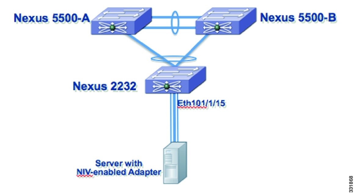
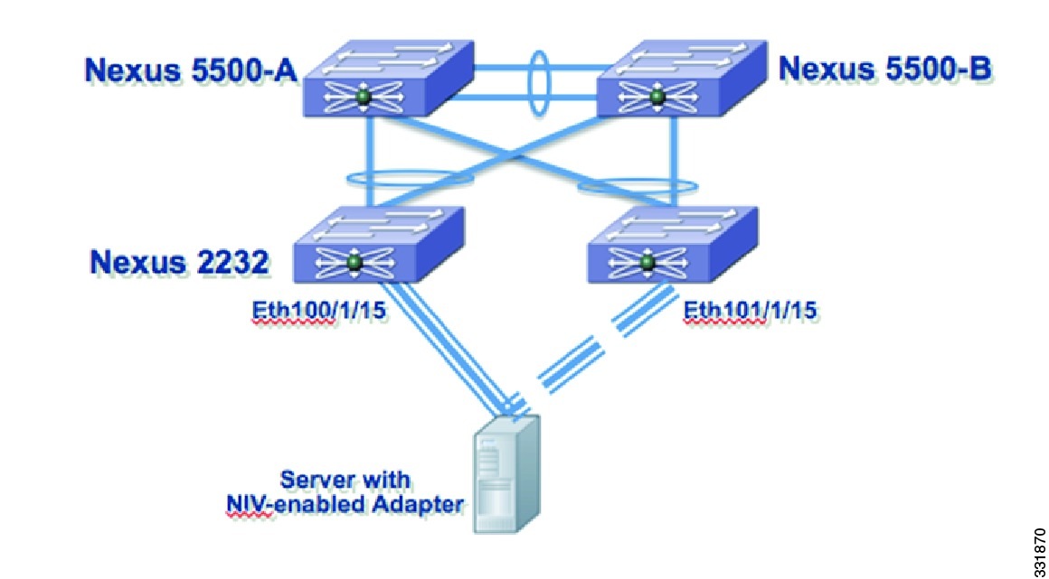
Figure 3-6 shows a server network adapter connected to dual-homed Cisco Nexus 2000 Series Fabric Extenders that are connected to two peer Cisco Nexus 5500 Series devices in a virtual port channel (vPC) topology. The active uplink interface of the adapter is connected to Ethernet 100/1/15 on the Fabric Extender and the standby uplink interface to Ethernet 101/1/15 on the second Fabric Extender.
Figure 3-6 Adapter-FEX-Enabled Server with Active-Standby Uplinks to Dual-Homed FEXs
Troubleshooting
This section explains troubleshooting procedures.
Removing a Server with a Server Network Adapter
When a server that is connected to the server network adapter is connected to a Cisco Nexus 5500 Series device, virtual Ethernet interfaces are created to support the server network adapter. When you disconnect or power down the server, virtual Ethernet interfaces are set to the down state and remain on the device until they are manually deleted.
Before you permanently disconnect the server, make sure that you delete all virtual Ethernet interfaces from the device using the no interface virtual Ethernet command and save the running system configuration using the copy running-config startup-config command.
Relocating a Server to a Different Physical Interface
When a server that is connected to the server network adapter is relocated from one physical interface on a Cisco Nexus 5500 Series device to another interface on the same device, new virtual Ethernet interfaces are created and are bound to the new physical interface. The original virtual Ethernet interfaces that were bound to the original physical interface exist until they are deleted. Make sure that you delete the original virtual Ethernet interfaces from the device using the no interface virtual Ethernet command and save the running system configuration using the copy running-config startup-config command.
When a new server is connected to the physical interface that was originally connected to the relocated server that has a server network adapter (the original virtual Ethernet interfaces that were bound to this physical interface exist), the virtual Ethernet interfaces are reused. This topology leads to a configuration conflict on the device and server network adapter (see the "Configuration Conflicts Between the Switch and Server Network Adapter" section).
In a vPC topology, virtual Ethernet numbers for a vNIC must be identical on both vPC peers. Moving a server that has a server network adapter from one physical interface to another interface on one of the vPC peers without first deleting the virtual Ethernet interfaces on that peer device results in new virtual Ethernet interfaces with different numbers. This results in having the two vPC peers that are not synchronized and a virtual Ethernet interface not getting created. You should delete the original virtual Ethernet interfaces on the peer device before you connect the server to the new physical interface.
Procedure:
Step 1
switch# configure terminalswitch(config)# interface ethernet 1switch(config-if)# shutdownswitch(config-if)# exitswitch(config) #Step 2
switch(config)# no interface vethernet 1switch(config)#Repeat this step to delete all virtual Ethernet interfaces on the server.
Step 3
vPC Peer A:switch# configure terminalswitch(config)# interface ethernet 1switch(config-if)# no switchport mode vntagswitch(config-if)#vPC Peer B:switch# configure terminalswitch(config)# interface ethernet 1switch(config-if)# no switchport mode vntagswitch(config-if)#Step 4
Step 5
Step 6
Changes to Port Profiles
When a new port profile for a virtual Ethernet interface is added on the device, it is immediately passed to all connected server network adapters and becomes available on those adapters. Similarly, when a port profile is removed, its name is withdrawn from every connected server network adapter.
Since only port profile names are passed to the server network adapter, changing the configuration within a port profile does not pass the configuration changes to the server network adapter.
When you use a newly added port profile, such as associating it with a new or existing vNIC, you might need to reboot the server. For more information, see the documentation for your specific adapter.
When you delete a port profile, all virtual Ethernet interfaces associated with the port profile are set to the administratively down state.
Relocating a Server Network Adapter to a Different Server
When a server network adapter is moved from one server to another, the server network adapter configuration, such as the information about vNICs, moves with the server network adapter. The configuration is saved on the server network adapter.
Configuration Examples
This section describes the configuration examples:
Servers with Server Network Adapter Topology Configuration Examples
This section describes how to configure a server with a server network adapter for the Adapter-FEX.
Configuring the Adapter-FEX on the Device
You must enable the Adapter-FEX feature on each Cisco Nexus 5500 series device that is connected to the server with a server network adapter. You must also configure the device to support Adapter-FEX.
Procedure:
Step 1
switch# configure terminalswitch(config)# install feature-set virtualizationswitch(config)#Step 2
switch(config)# feature-set virtualizationswitch(config)#Step 3
switch(config)# virtual Ethernet auto-createswitch(config)#The Adapter-FEX feature is enabled on the device.
Step 4
This example shows how to create and configure a port profile, user_data, on the device:
switch(config)# port profile type virtual Ethernet user_dataswitch(config-port-prof)# switchport trunk allowed vlan 2-100switch(config-port-prof)# switchport trunk native vlan 2switch(config-port-prof)# switchport mode trunkswitch(config-port-prof)# state enabledswitch(config-port-prof)# exitswitch(config)#This example shows how to create and configure a port profile, user_management, on the device:
switch(config)# port profile type virtual Ethernet user_managementswitch(config-port-prof)# switchport access vlan 1switch(config-port-prof)# state enabledswitch(config-port-prof)# exitswitch(config)#This example shows how to create and configure a port profile, user_backup, on the device:
switch(config)# port profile type virtual Ethernet user_backupswitch(config-port-prof)# switchport mode trunkswitch(config-port-prof)# switchport trunk allowed vlan 2-100switch(config-port-prof)# switchport trunk native vlan 2switch(config-port-prof)# mac port access-group mac_acl1switch(config-port-prof)# ip port access-group ip_acl1 inswitch(config-port-prof)# ipv6 port traffic-filter ipv6_acl1 inswitch(config-port-prof)# state enabledswitch(config-port-prof)# exitswitch(config)#Step 5
switch(config)# interface ethernet1/5switch(config-if)# description ucs_vic2/0switch(config-if)# switchport mode vntagswitch(config-if)#The device is configured to support Adapter-FEX. Connect the uplink interfaces of the adapter from the server to the device or Fabric Extender.
This example shows a Cisco Nexus 5500 series configuration:
install feature-set virtualizationfeature-set virtualizationvethernet auto-createport-profile type vethernet user_dataswitchport trunk allowed vlan 2-100switchport trunk native vlan 2switchport mode trunkstate enabledport-profile type vethernet user_managementswitchport access vlan 1state enabledport-profile type vethernet user_backupswitchport mode trunkswitchport trunk allowed vlan 2-100switchport trunk native vlan 2mac port access-group mac_acl1ip port access-group ip_acl1 inipv6 port traffic-filter ipv6_acl1 instate enabledinterface Ethernet1/5description ucs_vic2/0switchport mode vntagServer Network Adapter Initial Handshake and Negotiation
When you connect the server network adapter to the VNTag-mode Ethernet port on the Cisco Nexus 5500 series device or a Fabric Extender that is connected to a Cisco Nexus 5500 series device, a handshake is initiated.
An exchange of information about NIV capabilities takes place and communications begin in VNTag mode. The device passes the list of configured port profiles (type vEthernet) to the adapter. These port profile names are displayed in the configuration utility of the server network adapter as options for selection.
Note
If the server network adapter is not connected to the device, it is still possible to configure the vNICs on the server. However, the port profile names are not available on the adapter.
Configuring the Adapter-FEX on the Adapter
Using the server network adapter configuration utility on the server, enable Network Interface Virtualization (NIV) on the adapter. See the documentation of your specific server network adapter for details.
To complete the configuration, you might have to reboot the server to reset the network adapter.
Note
Note
Configuring vNICs on the Adapter
Using the network adapter configuration utility on the server, create the appropriate number of vNICs. Create each vNIC with the appropriate properties, such as the unique channel number, MAC address, uplink failover properties, or port profile names.
Note
Each vNIC has a unique channel number associated with it. A vNIC is identified on the device by the bind command that associates a physical port and the channel number of the vNIC to a virtual Ethernet interface. See the documentation of your specific server network adapter for details.
Note
Note
When the VNTag connectivity is established, only port profile names (type vEthernet) are passed to the server network adapter. The configurations in the port profile are not passed to the server network adapter.
The port profiles names are displayed in the network adapter configuration utility as options for selection.
Initializing the Server Network Adapter
Consider the topology as shown in Figure 3-2 and Figure 3-3.
After configuring vNICs on the server network adapter, you might have to reload the drivers or reboot the server and the adapter to complete the configuration. See the documentation for your specific server network adapter for details.
When the configuration is complete, the server network adapter and the device re establishes a link and performs the initial handshake and negotiation process. The server network adapter and the device also establishes higher level control plane connectivity using the Virtual Interface Configuration (VIC) protocol.
Note
When the VIC protocol connectivity is established, the server network adapter requests that the device create a virtual Ethernet interface for each vNIC that is configured on the server network adapter. The server network adapter also passes the following attributes over the uplink interface in addition to the virtual Ethernet interface creation request:
•
•
•
•
The device creates a virtual Ethernet interface for each vNIC on the server network adapter and associates the port profile and channel number to the virtual Ethernet interface.
The server boot up process might be suspended at the BIOS configuration phase until virtual Ethernet interfaces are created. When the virtual Ethernet interfaces creation completes, the boot up process resumes and the OS is loaded. See the documentation for your specific adapter for details.
Note
Note
Note
Note
When you manually create virtual Ethernet interfaces, you can select any number for the virtual Ethernet interface. We recommend that you choose a number less that 32678, in the range from 1 to 2000.
This example shows the configuration that is associated with virtual Ethernet interfaces on the device:
interface vethernet 21bind interface ethernet 1/5 channel 1inherit port-profile user_datainterface vethernet 22bind interface ethernet 1/5 channel 2inherit port-profile user_datainterface vethernet 23bind interface ethernet 1/5 channel 3inherit port-profile user_managementinterface vethernet 24bind interface ethernet 1/5 channel 4inherit port-profile user_backupDual-Homed FEX Topology Configuration Examples
Consider the topology shown in Figure 3-4. Server network adapter initialization can take place when an uplink interface is connected to a dual-homed Fabric Extender.
When the virtual Ethernet interface creation is complete, the virtual Ethernet interface configuration on the Cisco Nexus 5500-A device is as follows:
interface vethernet 21bind interface ethernet 101/1/15 channel 1inherit port-profile user_datainterface vethernet 22bind interface ethernet 101/1/15 channel 2inherit port-profile user_datainterface vethernet 23bind interface ethernet 101/1/15 channel 3inherit port-profile user_managementinterface vethernet 24bind interface ethernet 101/1/15 channel 4inherit port-profile user_backupThe virtual Ethernet interface configuration on the Cisco Nexus 5500-B device is as follows:
interface vethernet 21bind interface ethernet 101/1/15 channel 1inherit port-profile user_datainterface vethernet 22bind interface ethernet 101/1/15 channel 2inherit port-profile user_datainterface vethernet 23bind interface ethernet 101/1/15 channel 3inherit port-profile user_managementinterface vethernet 24bind interface ethernet 101/1/15 channel 4inherit port-profile user_backup
Note
Active-Standby Server Network Adapter Topology Configuration Examples
This section includes the following topics:
•
•
Adapter-FEX Initialization with Active-Standby Uplinks in vPC Topology
Consider the topology in Figure 3-5 that has one uplink interface as active and the other uplink interface as standby. Channel numbers for virtual Ethernet interfaces created on the standby uplink device are the same as the channel numbers on the active uplink interface.
In a vPC topology, the virtual Ethernet interfaces associated with a single vNIC will have the same interface number on the vPC primary and secondary device.
Assume that the server network adapter in this example has four vNICs (eth0, eth1, eth2, eth3) and two uplinks (uplink_0, uplink_1) with the following configuration:
Also assume that uplink_0 is connected to Ethernet 1/5 on the Cisco Nexus 5500-A device and uplink_1 is connected to Ethernet 1/15 on the Cisco Nexus 5500-B device.
When the virtual Ethernet interface creation completes, the virtual Ethernet interface configuration on the Cisco Nexus 5500-A device is as follows:
interface vethernet 37bind interface ethernet 1/5 channel 1inherit port-profile user_datainterface vethernet 38bind interface ethernet 1/5 channel 2inherit port-profile user_datainterface vethernet 39bind interface ethernet 1/5 channel 3inherit port-profile user_managementinterface vethernet 40bind interface ethernet 1/5 channel 4inherit port-profile user_backupThe virtual Ethernet interface configuration on the Cisco Nexus 5500-B device is as follows:
interface vethernet 37bind interface ethernet 1/5 channel 1inherit port-profile user_datainterface vethernet 38bind interface ethernet 1/5 channel 2inherit port-profile user_datainterface vethernet 39bind interface ethernet 1/5 channel 3inherit port-profile user_managementinterface vethernet 40bind interface ethernet 1/5 channel 4inherit port-profile user_backup
Note
In a vPC active-standby topology, virtual Ethernet interface numbers are allocated only by the vPC primary device. When a virtual Ethernet interface create request is received, the vPC secondary device requests the primary device for an allocation. The show vpc brief command displays the vPC role of a device.
If a server that is connected to a server network adapter is moved from one physical interface to another on just one of the vPC peers, the server network adapter connectivity is not established until the old virtual Ethernet interfaces are deleted.
Adapter-FEX Initialization with Active-Standby Uplinks Dual-Homed FEXs
Consider the topology shown in Figure 3-6 that has one uplink interface as active and the other uplink interface as standby.
Assume that the network server adapter has four vNICs (eth0, eth1, eth2, eth3) and two uplinks (uplink_0, uplink_1) with the following configuration:
:
Also assume that uplink_0 is connected to Ethernet 100/1/15 on the Fabric Extender and uplink_1 is connected to Ethernet 101/1/15 on the Fabric Extender.
When the virtual Ethernet interface creation completes, the virtual Ethernet interface configuration on the Cisco Nexus 5500-A device is as follows:
interface vethernet 37bind interface ethernet 100/1/15 channel 1bind interface ethernet 101/1/15 channel 1inherit port-profile user_datainterface vethernet 38bind interface ethernet 100/1/15 channel 2bind interface ethernet 101/1/15 channel 2inherit port-profile user_datainterface vethernet 39bind interface ethernet 100/1/15 channel 3bind interface ethernet 101/1/15 channel 3inherit port-profile user_managementinterface vethernet 40bind interface ethernet 100/1/15 channel 4bind interface ethernet 101/1/15 channel 4inherit port-profile user_backupThe virtual Ethernet interface configuration on the Cisco Nexus 5500-B device is as follows:
interface vethernet 37bind interface ethernet 100/1/15 channel 1bind interface ethernet 101/1/15 channel 1inherit port-profile user_datainterface vethernet 38bind interface ethernet 100/1/15 channel 2bind interface ethernet 101/1/15 channel 2inherit port-profile user_datainterface vethernet 39bind interface ethernet 100/1/15 channel 3bind interface ethernet 101/1/15 channel 3inherit port-profile user_managementinterface vethernet 40bind interface ethernet 100/1/15 channel 4bind interface ethernet 101/1/15 channel 4inherit port-profile user_backup
Note
Configuring Virtual Ethernet Interfaces
This section describes how to create and configure a virtual Ethernet interface.
Creating Virtual Ethernet Interfaces Automatically
This section describes how to create virtual Ethernet interfaces automatically when a server network adapter is connected to a VNTag-mode Ethernet interface on a Cisco Nexus 5500 series device.
The server network adapter requests the Cisco Nexus 5500 series device to create a virtual Ethernet interfaces one at a time.
Saving Virtual Ethernet Interface in a Startup Configuration File
Virtual Ethernet interfaces that are created with a request to create the VIC protocol interface are stored in the running configuration. If the running configuration is saved, the virtual Ethernet interfaces and their configurations are saved to the startup configuration file.
When you reload the device, the device loads the startup configuration file and the virtual Ethernet interface is created statically from the startup configuration. When the VNTag interface is initialized and the server network adapter makes a request to create a virtual Ethernet interface, the already existing virtual Ethernet interface is used. For more information, see the "Configuring Virtual Ethernet Interfaces Manually" section.
A virtual Ethernet interface can be deleted from the system with the no interface vethernet command. Since virtual Ethernet interfaces are saved in the startup configuration, we recommend that you save the running configuration to the startup configuration file.
Configuring Virtual Ethernet Interfaces Manually
You can manually create virtual Ethernet interfaces on a Cisco Nexus 5500 series device using the interface vethernet command. You can configure a maximum of 2000 virtual Ethernet interfaces on a Cisco Nexus 5500 series device.
Note
When a device connected to a server network adapter receives a request to create a virtual Ethernet interface, the device checks for a manually configured virtual Ethernet interface that matches the channel number of the virtual Ethernet interface creation request. If the manually configured virtual Ethernet interface already exists, the manually configured virtual Ethernet interface is used and a new virtual Ethernet interface is not created. If the virtual Ethernet interface does not exist, a new virtual Ethernet interface is created.
Note
Configuration Conflicts Between the Switch and Server Network Adapter
Conflicts with port profile names may occur between the configuration of a virtual Ethernet interface that was manually configured or one that was saved in the start up configuration and the configuration on the server network adapter.
For example, the server network adapter might associate the vNIC with channel number 5 to the port profile user_backup, whereas the device might associate the virtual Ethernet interface bound to channel number 5 to the port profile user_data.
When a conflict of this kind occurs, the configuration from the server network adapter takes precedence and overwrites the configuration on the device.
When a port profile is associated to a vNIC, but the port profile does not exist on the device, the virtual Ethernet interface creation and initialization fails.