Feedback
Table Of Contents
Information About Enhanced vPC
Enhanced vPC Topology and Scalability
Supported Enhanced vPC Topology
Unsupported Enhanced vPC Topology
vPC Between Hosts and a Pair of FEXs that are Connected to a Single Cisco Nexus 5500 Series Device
Port Channel Between Host and Ports from More Than Two FEXs
Total Number of FEXs Per Cisco Nexus 5000 Series Device
SAN A and SAN B Traffic Isolation
Port Channel Member Port Failure
Cisco Nexus 5000 Series Switch Failure
Deploying and Monitoring Enhanced vPC
Enhanced vPC Consistency Checks
Different Port Channel Members
Port Channel Interface Level Configuration Checks
FCoE Configuration with Enhanced vPC
Software Upgrade with Enhanced vPC
Monitoring the Traffic in Enhanced vPC
Using Enhanced vPC
This chapter provides an overview of Enhanced virtual port channelling(vPC).
This chapter includes the following sections:
•
Information About Enhanced vPC
•
•
•
Information About Enhanced vPC
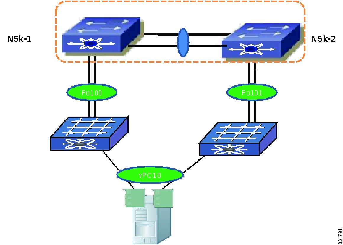
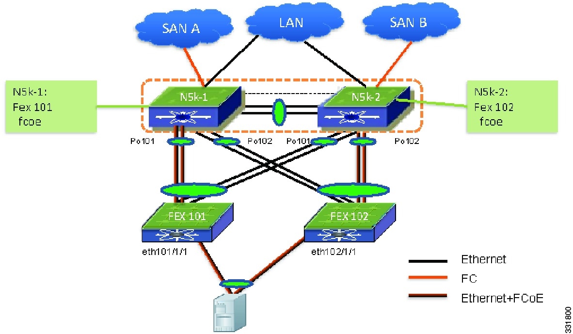
Enhanced vPC enables you to support server connectivity with one topology and address requirement for both high availability and high bandwidth. Enhanced vPC is technology that supports the topology that is shown in Figure 6-1, where a Cisco Nexus 2000 Fabric Extender (FEX) is dual-homed to a pair of Cisco Nexus 5500 Series devices while the hosts are also dual-homed to a pair of FEXs using a vPC.
Figure 6-1 Enhanced vPC Topology
With Enhanced vPC, all available paths from hosts to FEXs and from FEXs to the Cisco Nexus 5500 Series device are active, carry Ethernet traffic, and maximize the available bandwidth. All available paths in the Enhanced vPC topology can carry Ethernet traffic.
With Enhanced vPC, you could choose either a single-homed FEX topology see Figure 6-2 or a dual-homed FEX topology see Figure 6-3 for a dual-homed FEX topology example.
The single-homed FEX topology is well suited for servers with multiple NICs that support 802.3ad port channel. The dual-homed FEX topology is ideal for servers with one NIC, because the failure of one Cisco Nexus 5500 Series device does not bring down the FEX and does not cut the single NIC server out of the network. The Dual-homed FEX topology can also be deployed for servers that have multiple NICs but do not support 802.3ad. Without an Enhanced vPC server, you cannot connect port channels to FEXs when the FEXs are dual-homed to both Cisco Nexus 5500 Series devices.
Figure 6-2 Single-Homed FEX Topology
Figure 6-3 Dual-Homed FEX Topology
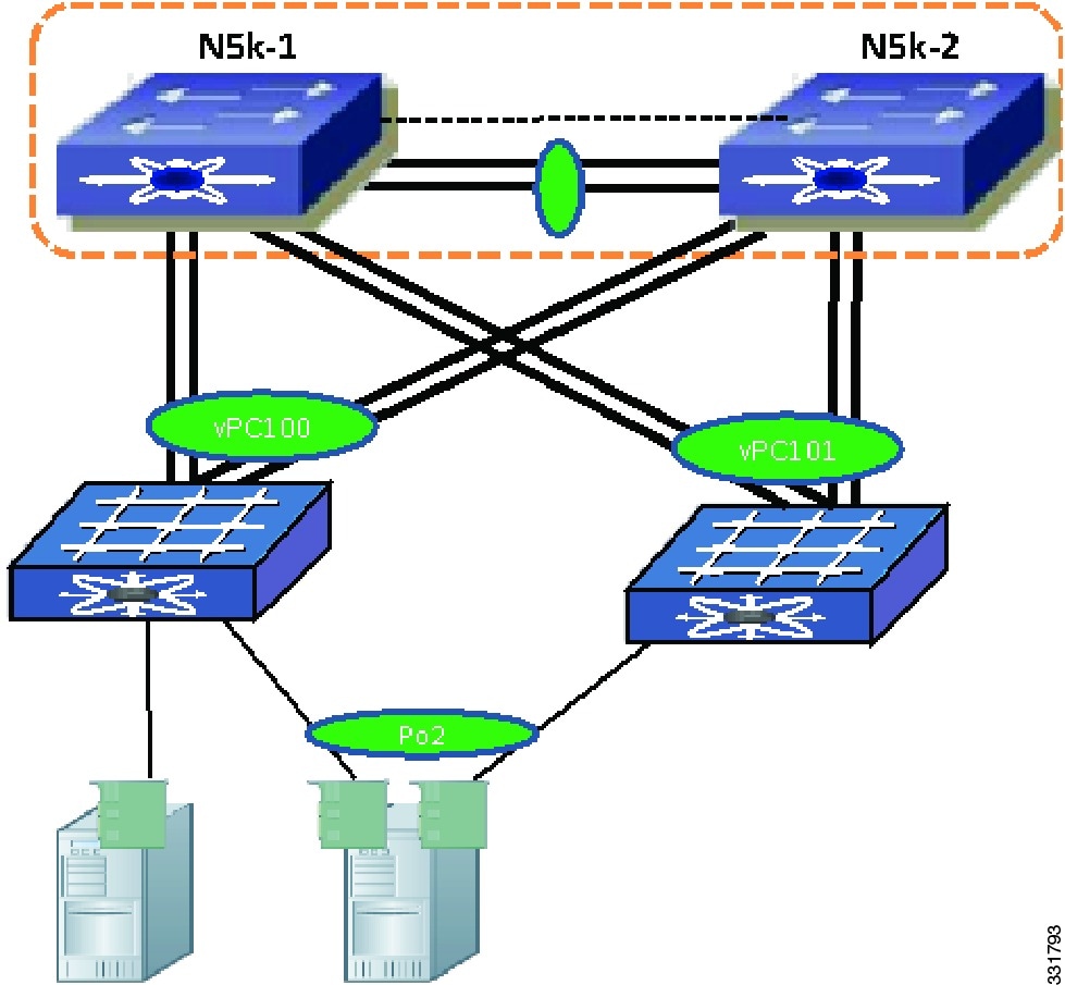
Use Enhanced vPC if you want to connect a dual-homed FEX to a Cisco Nexus 5000 Series device to have better redundancy for a single NIC server and at the same time, want to run port channels between the servers that have multiple NICs and FEXs. See Figure 6-4 for an example of enhanced vPC with a single-homed server and host vPC.
Figure 6-4 Enhanced vPC with Single-Homed Server and Host vPC
Supported Platform
Cisco NX-OS 5.1(3)N1(1) supports Enhanced vPC on the Cisco Nexus 5548P, Cisco Nexus 5548UP, and Cisco Nexus 5596UP devices. The Cisco Nexus 5010 and Cisco Nexus 5020 devices cannot support Enhanced vPC. Enhanced vPC is implemented on the Cisco Nexus 5500 Series device and has no specific requirements from a FEX. As a result, different types of FEXs can be deployed in an Enhanced vPC topology.
Enhanced vPC is also supported with Layer 3 running on Cisco Nexus 5500 Series devices, but it does not change any Layer 3 CLI or how Layer 3 features are implemented on a Cisco Nexus 5500 Series device.
With the introduction of the Enhanced vPC, the three topologies supported by a Cisco Nexus 5500 Series device and FEX are the single-homed FEX topology, the dual-homed FEX topology, and the Enhanced vPC topology. A hybrid topology is also supported, where the FEX and hosts are connected to the same pair of Cisco Nexus 5500 Series devices.
Enhanced vPC Topology and Scalability
Supported Enhanced vPC Topology
Figure 6-5 shows various server connections that are supported with an Enhanced vPC topology.
Figure 6-5 Enhanced vPC with Various Types of Server Connections
The figure shows the following configurations:
•
•
•
•
•
•
•
Unsupported Enhanced vPC Topology
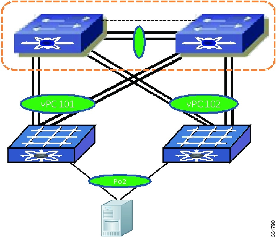
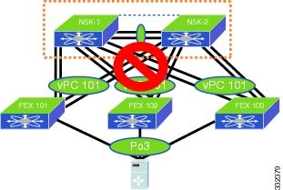
vPC Between Hosts and a Pair of FEXs that are Connected to a Single Cisco Nexus 5500 Series Device
Figure 6-6 shows unsupported topology where a vPC is between hosts and two FEXs that are connected to one Cisco Nexus 5500 Series device. This topology does not provide a good high availability solution because the server loses the connectivity to the network when the Cisco Nexus 5000 Series device fails.
Figure 6-6 Unsupported Topology—Host vPC With One Cisco Nexus 5000 Series Device
If you need to connect a multi-homing server to a pair of FEXs when there is only one Cisco Nexus 5000 Series device, you have the option to run active or standby NIC teaming from the server.
Port Channel Between Host and Ports from More Than Two FEXs
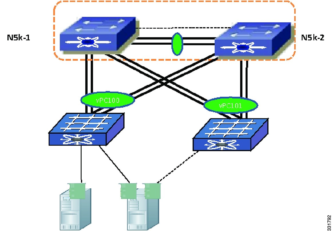
With Enhanced vPC, the port channel can be formed among ports from up to two FEXs that are connected to the same pair of Cisco Nexus 5000 Series devices. This topology which is shown in Figure 6-7, does not work and is not supported.
Figure 6-7 Unsupported Topology—Host vPC Spans Across More Than Two FEXs
This topology adds little value in terms of high availability but increases the complexity of cabling and management. The CLI rejects the configuration when it detects the port channel members are from more than two FEXs.
Enhanced vPC Scalability
In general, the Enhanced vPC does not change the scalability of a Cisco Nexus 5000 Series device and a FEX. Scalability is similar to the dual-homed FEX topology.
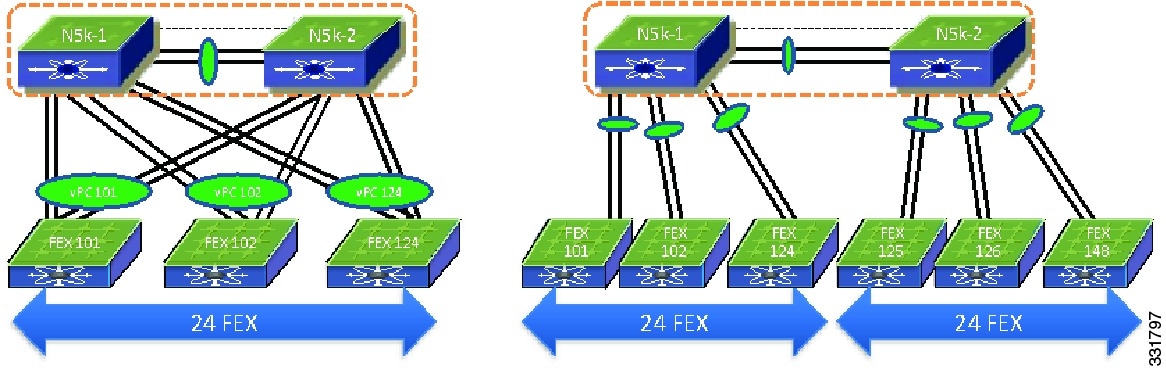
Total Number of FEXs Per Cisco Nexus 5000 Series Device
From the Cisco NX-OS 5.1(3)N1(1) release and later releases, each Cisco Nexus 5500 Series device can manage and support up to 24 FEXs without Layer 3. With Layer 3, the number of FEXs supported per Cisco Nexus 5500 Series device is 8. With Enhanced vPC and a dual-homed FEX topology each FEX is managed by both Cisco Nexus 5000 Series devices. As a result, one pair of Cisco Nexus 5500 Series devices can support up to 24 FEXs and 16 FEXs for Layer 2 and Layer 3.
There are differences in scalability between the straight-through topology, the dual-homed FEX topology, and the Enhanced vPC topology. In the straight through topology, only one Cisco Nexus 5000 Series device manages each FEX and a pair of Cisco Nexus 5500 Series devices manage up to 48 FEXs. This difference is shown in Figure 6-8 for an Layer 2 scenario.
Figure 6-8 FEX Scalability
Because the total number of FEXs that are supported by a pair of Cisco Nexus 5000 Series devices is different between these two topologies, the FEX straight-through design with more than 24 FEXs per one pair of Cisco Nexus 5000 Series devices cannot migrate to Enhanced vPC topology.
The configurations are as follows:
•
•
The Cisco Nexus 2148 device does not support port channels. With the Cisco Nexus 2148 device, the host vPC can have up to two ports with one from each Cisco Nexus 2148.
The Cisco Nexus 2248, Cisco Nexus 2224, Cisco Nexus 2232 and Cisco Nexus 2248TP-E devices support hardware port channels and up to 16 ports in a host vPC with up to 8 ports from each FEX.
Enhanced vPC with FCoE
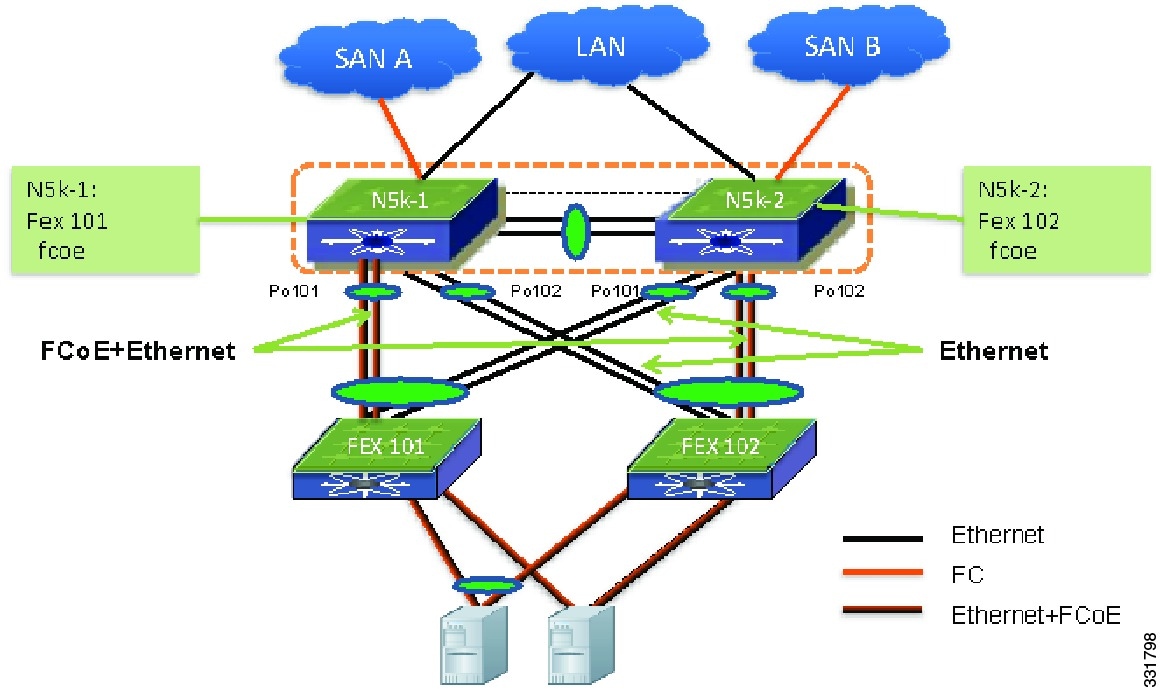
SAN A and SAN B Traffic Isolation
You can deploy FCoE in an Enhanced vPC topology. Traditionally, the SAN network maintains two fabrics, the SAN A and SAN B. The traffic from side A is isolated from side B. Hosts and storage arrays are attached to host SAN networks for high availability. The FCoE traffic in an Enhanced vPC topology maintain the traffic isolation for two SAN networks. The FCoE command ensures the FCoE traffic from the FEX is only sent to one Cisco Nexus 5000 Series device is as follows:
N5k-1(config)# fex 101N5k-1(config-fex)# fcoeN5k-2(config)# fex 102N5k-2(config-fex)# fcoeIn this configuration, the FCoE traffic from FEX 101 is sent only to N5k-1 and the FCoE traffic from FEX 102 is sent only to N5k-2 although both FEXs are connected to both devices. This is true for the reverse FCoE traffic from a Cisco Nexus 5000 Series device to a FEX where the FCoE traffic is sent only on a FEX. As a result, SAN A and SAN B separation is achieved.
Starting the Cisco NX-OS 5.1(3)N1(1) release, FCoE is supported for an Enhanced vPC topology and dual-homed FEX topology.
For an Ethernet-only network with Enhanced vPC, you have the option to connect hosts to random selected pairs of FEXs, such as the host H3 and H4 in Figure 6-9. However, this approach is not recommended because it may have hosts connected to the two FEXs that are mapped to the same side of a SAN network.
From the Cisco NX-OS 5.1(3)N1(1) release and later releases, the topology that has four ports in the host vPC (two ports to each FEX) is not supported.
Figure 6-9 FCoE Traffic Flow with Enhanced vPC
FEX Uplink Traffic Load
In the Enhanced vPC topology, the traffic load for the FEX uplinks is not even, because the FCoE traffic from a FEX is forwarded to one Cisco Nexus 5000 Series device for SAN traffic isolation. Po101 between N5k-1 and FEX 101, and Po102 between N5k-2 and FEX 102 carries more traffic than the rest of two the port channels between a FEX and a Cisco Nexus 5000 Series device. You must provision enough bandwidth to prevent the undesirable oversubscription for links that carry both FCoE and Ethernet traffic.
To avoid the imbalance of traffic distribution, we recommend a FEX straight-through topology for FCoE deployments that have a FEX. In an enhanced vPC topology, you can have only up to four 10-Gigabyte Ethernet links for FCoE traffic for each of the Cisco Nexus 2232 devices. However, in a FEX straight-through topology, all eight 10-Gigabyte Ethernet uplinks can carry FCoE traffic.
You can control how the bandwidth of a FEX uplink is shared between the Ethernet and FCoE traffic by configuring an ingress and egress queuing policy. The default QoS template allocates half of the bandwidth to each. For the links that carry both Ethernet and FCoE traffic, each gets half of the guaranteed bandwidth in case of congestion. When there is congestion, each type of traffic can take all available bandwidth. For links that carry only Ethernet traffic, all 10-Gbps bandwidth is available for Ethernet traffic.
Enhanced vPC Failure Reaction
Port Channel Member Port Failure
If one port channel member fails, the traffic flow is moved to the remaining port channel members. If the host loses all its connections to one FEX, the traffic flow is redirected to another flow for both host to network and network to host.
FEX Failure
If a FEX fails, all flows are moved to the second FEX in the Enhanced vPC topology. For both directions, the traffic does not need to traverse the vPC peer link.
Cisco Nexus 5000 Series Switch Failure
When one Cisco Nexus 5000 Series device goes down, all FEXs remain connected to the other Cisco Nexus 5000 Series devices. All FEX front panel ports are still operational. All traffic flows continue to be forwarded by all FEXs.
FEX Uplink Failure
When a FEX loses its uplinks, it shuts down its front panel ports and the traffic is carried by another FEX for Enhanced vPC topology.
vPC Peer-Link Failure
When the vPC secondary device detects a peer-link failure it checks if the primary device is alive via a peer keepalive link. If the primary device is alive, the secondary device suspends all its vPC member ports. In an Enhanced vPC topology, the vPC secondary device suspends all the interfaces that connects to a FEX. As a result, all FEXs are connected only to a vPC primary device. All FEX host ports are up and running and traffic continues to be distributed to both FEXs.
Because the FEXs are not connected to a vPC secondary device when the peer-link fails, the vPC secondary device cannot carry the FCoE traffic and the secondary device shuts down all the VFC interfaces that are bound to the FEX host ports. The multi pathing software that runs on the host moves all the SAN traffic flow to the remaining VFC interface.
If the secondary device cannot reach the primary device via the keepalive link, the secondary device keeps its vPC member ports up and running.
vPC Keepalive Failure
The vPC keepalive failure does not have any impact on the vPC and traffic flow. We recommend that you check and restore the keepalive link as soon as possible.
Deploying and Monitoring Enhanced vPC
Enhanced vPC Configuration
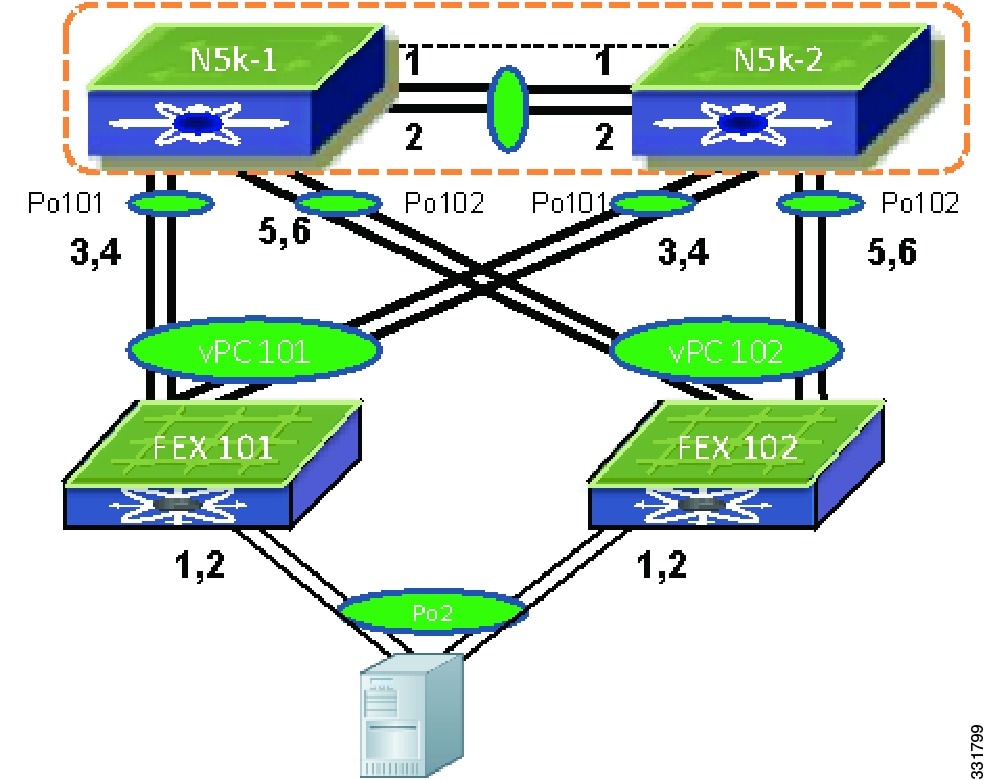
In the Enhanced vPC topology, the FEXs are virtual line cards and the FEX front panel ports are mapped to the virtual interfaces on a parent Cisco Nexus 5000 Series device. From the CLI perspective, the configuration of Enhanced vPC is the same as a regular port channel with member ports from two FEXs. You do not have to enter the CLI vpc vpc ID to create an Enhanced vPC. An example of how to create an Enhanced vPC with topology.
The following procedure uses the topology in Figure 6-10. In the figure, the number next to the line is the interface ID. Assume all the ports are base ports the interface ID 2 represent interface eth1/2 on the Cisco Nexus 5000 Series device.
Figure 6-10 Creating an Enhanced vPC Topology
Configuration on the first Cisco Nexus 5000 Series device:
N5k-1(config)# interface eth101/1/, eth101/1/2N5k-1(config-if)# channel-group 2 mode activeN5k-1(config-if)# interface eth102/1/, eth102/1/2N5k-1(config-if)# channel-group 2 mode activeConfiguration from the second Cisco Nexus 5000 Series device:
N5k-2(config)# interface eth101/1/, eth101/1/2N5k-2(config-if)# channel-group 2 mode activeN5k-2(config-if)# interface eth102/1/, eth102/1/2N5k-2(config-if)# channel-group 2 mode activeAlthough the vPC vPC ID command is not required, the software assigns an internal vPC ID for each Enhanced vPC. The output of the show vpc command displays this internal vPC ID.
Step 1
N5k-1(config)# feature vpcN5k-1(config)# feature lacpN5k-2(config)# feature vpcN5k-2(config)# feature lacpStep 2
N5k-1(config)# vlan 10-20N5k-2(config)# vlan 10-20Step 3
N5k-1(config)# vpc domain 123N5k-1(config-vpc)# peer-keepalive destination 172.25.182.100N5k-2(config)# vpc domain 123N5k-2(config-vpc)# peer-keepalive destination 172.25.182.99Step 4
N5k-1(config)# interface eth1/1-2N5k-1(config-if)# channel-group 1 mode activeN5k-1(config-if)# interface Po1N5k-1(config-if)# switchport mode trunkN5k-1(config-if)# switchport trunk allowed vlan 1, 10-20N5k-1(config-if)# vpc peer-linkN5k-2(config)# interface eth1/1-2N5k-2(config-if)# channel-group 1 mode activeN5k-2(config-if)# interface Po1N5k-2(config-if)# switchport mode trunkN5k-2(config-if)# switchport trunk allowed vlan 1, 10-20N5k-2(config-if)# vpc peer-linkStep 5
N5k-1(config)# fex 101N5k-1(config-fex)# interface eth1/3-4N5k-1(config-if)# channel-group 101N5k-1(config-if)# interface po101N5k-1(config-if)# switchport mode fex-fabricN5k-1(config-if)# vpc 101N5k-1(config-if)# fex associate 101N5k-2(config)# fex 101N5k-2(config-fex)# interface eth1/3-4N5k-2(config-if)# channel-group 101N5k-2(config-if)# interface po101N5k-2(config-if)# switchport mode fex-fabricN5k-2(config-if)# vpc 101N5k-2(config-if)# fex associate 101Step 6
N5k-1(config)# fex 102N5k-1(config-fex)# interface eth1/5-6N5k-1(config-if)# channel-group 102N5k-1(config-if)# interface po102N5k-1(config-if)# switchport mode fex-fabricN5k-1(config-if)# vpc 102N5k-1(config-if)# fex associate 102N5k-2(config)# fex 102N5k-2(config-fex)# interface eth1/5-6N5k-2(config-if)# channel-group 102N5k-2(config-if)# interface po102N5k-2(config-if)# switchport mode fex-fabricN5k-2(config-if)# vpc 102N5k-2(config-if)# fex associate 102Step 7
N5k-1(config)# interface eth101/1/1, eth101/1/2N5k-1(config-if)# channel-group 2 mode activeN5k-1(config-if)# interface eth102/1/1, eth102/1/2N5k-1(config-if)# channel-group 2 mode activeN5k-1(config-if)# int po2N5k-1(config-if)# switchport access vlan 10N5k-2(config)# interface eth101/1/1, eth101/1/2N5k-2(config-if)# channel-group 2 mode activeN5k-2(config-if)# interface eth102/1/1, eth102/1/2N5k-2(config-if)# channel-group 2 mode activeN5k-2(config-if)# int po2N5k-2(config-if)# switchport access vlan 10As shown in the above procedure, the Enhanced vPC configuration is the same configuration as when you configure the host port channel with channel members from the same FEX.
Enhanced vPC Consistency Checks
Cisco NX-OS checks whether the vPC-related configuration is consistent between the two vPC peer devices to avoid undesired data forwarding behavior. Cisco NX-OS checks both global configuration parameters and interface level configuration parameters. For Enhanced vPC, the consistency check for global configuration parameters remain the same as for a dual-homed FEX topology. For details about the vPC consistency check, see the vPC operation guide:
http://www.cisco.com/en/US/docs/switches/datacenter/nexus5000/sw/operations/n5k_vpc_ops.html
Port Channel ID Checks
Cisco NX-OS requires that the same port channel ID is used on two peer devices for Enhanced vPC. The port channel and its channel members are suspended when different port channel IDs are used for the same FEX ports. The following example shows that the FEX interfaces eth110/1/1 and eth111/1/1 are assigned to different port channels on the two vPC devices. As a result, the two FEX interfaces are suspended on both Cisco Nexus 5000 Series devices and the port channel is not operational.
N5596-1# show run int e110/1/1,e111/1/1!Command: show running-config interface Ethernet110/1/1, Ethernet111/1/1!Time: Sun Aug 28 03:38:23 2011version 5.1(3)N1(1)interface Ethernet110/1/1channel-group 1002interface Ethernet111/1/1channel-group 1002N5596-2# show run int e110/1/1,e111/1/1!Command: show running-config interface Ethernet110/1/1, Ethernet111/1/1!Time: Mon Aug 29 21:01:20 2011version 5.1(3)N1(1)interface Ethernet110/1/1hardware N2348TP queue-limit 1024000 rxhardware N2348TP queue-limit 1024000switchport access vlan 20channel-group 1001interface Ethernet111/1/1switchport access vlan 20channel-group 1001N5596-2#N5596-2# show int e110/1/1Ethernet110/1/1 is down (suspended by vpc)Hardware: 100/1000 Ethernet, address: 7081.0500.2402 (bia 7081.0500.2402)MTU 1500 bytes, BW 1000000 Kbit, DLY 10 usec<snip>N5596-1# show int e110/1/1Ethernet110/1/1 is down (suspended by vpc)Hardware: 100/1000 Ethernet, address: 7081.0500.2402 (bia 7081.0500.2402)MTU 1500 bytes, BW 1000000 Kbit, DLY 10 usec<snip>Different Port Channel Members
The port channel is up and operational when there is at least one common port channel member between the two Cisco Nexus 5000 Series devices. The FEX interfaces that are assigned to A port channel on only one Cisco Nexus 5000 Series device are suspended. In the following example, FEX interfaces eth110/1/1 and eth111/1/1, are assigned to Po1001 on N5596-1. However, on N5596-2 only eth110/1/1 is assigned to Po1001. Therefore, only eth110/1/1 becomes the active port channel member and Po1001 is up on both Cisco Nexus 5000 Series devices. FEX interface eth111/1/1 is suspended on both Cisco Nexus 5000 Series devices. With this configuration, the host is connected only to FEX 110.
N5k-1(config)# interface eth110/1/1, eth111/1/1N5k-1(config-if)# channel-group 1001N5k-1(config-if)# int po1001N5k-1(config-if)# switchport access vlan 20N5k-2(config)# interface eth110/1/1N5k-2(config-if)# channel-group 1001N5k-2(config-if)# int po1001N5k-2(config-if)# switchport access vlan 20N5596-1(config)# show int e111/1/1Ethernet111/1/1 is down (suspended by vpc)Hardware: 100/1000 Ethernet, address: 7081.0500.2582 (bia 7081.0500.2582)MTU 1500 bytes, BW 1000000 Kbit, DLY 10 usecreliability 255/255, txload 1/255, rxload 1/255N5596-1# show port-channel summaryFlags: D - Down P - Up in port-channel (members)I - Individual H - Hot-standby (LACP only)s - Suspended r - Module-removedS - Switched R - RoutedU - Up (port-channel)M - Not in use. Min-links not metTable 6-1 shows the port channel summary for N5596-1.
Table 6-1 Port Channel Summary for N5596-1
N5596-1#N5596-2# show int e111/1/1Ethernet111/1/1 is down (suspended by vpc)Hardware: 100/1000 Ethernet, address: 7081.0500.2582 (bia 7081.0500.2582)MTU 1500 bytes, BW 1000000 Kbit, DLY 10 usecreliability 255/255, txload 1/255, rxload 1/255N5596-2# show port-channel summaryFlags: D - Down P - Up in port-channel (members)I - Individual H - Hot-standby (LACP only)s - Suspended r - Module-removedS - Switched R - RoutedU - Up (port-channel)M - Not in use. Min-links not metTable 6-2 shows the port channel summary for N5596-2.
Table 6-2 Port Channel Summary for N5596-2
Global vPC Consistency Check
The configuration that is subject to a global vPC consistency check is displayed as follows:
N5596-1# show vpc consistency-parameters globalLegend:Type 1 : vPC will be suspended in case of mismatchTable 6-3 shows the vPC consistency check.Table 6-3 vPC Consistency Check
For a type 2 consistency check parameter, a warning message displays to remind you to have identical configurations on both vPC devices. The vPC and vPC member ports is up and running on both Cisco Nexus 5000 Series devices. Starting in the Cisco NX-OS 5.0(2)N2(1) release, an enhancement called Graceful consistency check was introduced to improve the resilience for vPC. With this feature, the mismatch of the type 1 consistency check parameter on a vPC secondary device, suspends its vPC member port. The vPC primary device keeps the vPC member ports operational to avoid the complete loss of connectivity for a network device behind a vPC.
The graceful consistency check feature does not work for the dual-homed FEX topology and Enhanced vPC topology. With the mismatch of the type 1 consistency check parameters, both vPC devices suspend their vPC member ports for a dual-homed FEX and Enhanced vPC. For example, the output shown above indicates that the STP mode is configured differently on two Cisco Nexus 5596 devices. All the interfaces from dual-homed FEXs are suspended due to the mismatch of the type-1 configuration.
The vPC graceful consistency check works for the FEX straight through topology.
Port Channel Interface Level Configuration Checks
Under the port channel for Enhanced vPC configuration the two important parameters are the port mode (access vs. trunk) and the allowed VLAN for trunk mode.
The applicable configuration parameters that are subject to interface level consistency check are displayed with CLI show vpc consistency check interface.
N5K# show vpc consistency-parameters interface po1000Legend:Type 1 : vPC will be suspended in case of mismatchTable 6-4 shows the port channel interface level configuration checks.Table 6-4 Port Channel Interface Level Configuration Checks
FCoE Configuration with Enhanced vPC
Prior to the Cisco NX-OS 5.1(3)N1(1) release, when an Ethernet interface was a port channel member, the VFC interface could only be bound to a port channel.
This example shows how to configure FCoE with Enhanced vPC:
interface eth100/1/1Channe-group 1001Interface Po1001Switchport mode trunkSwitchport trunk allowed vlan 1, 100,2000Interface vfc 1bind interface Po1001This configuration model requires that there is only one member for the port channel. It cannot be supported for Enhanced vPC where the port channel has at least two interfaces. Starting from the Cisco NX-OS 5.1(3)N1(1) release and later releases the VFC interface can be bound to physical interfaces.
Figure 6-11 shows an FCoE configuration topology.
Figure 6-11 FCoE Configuration Example Topology
This example shows how to configure the topology that is shown in Figure 6-11:
N5k-1(config)# fex 101N5k-1(config-fex)# fcoeN5k-1(config-fex)# interface vfc1N5k-1(config-if)# bind interface eth101/1/1N5k-2(config)# fex 102N5k-2(config-fex)# fcoeN5k-2(config-fex)# interface vfc1N5k-2(config-if)# bind interface eth102/1/1The FCoE portion of the configuration on the two vPC devices are different for the SAN traffic isolation and they are not subject to vPC consistency check.
You can enter the fcoe command to create an association between a FEX and a Cisco Nexus 5000 Series device for FCoE traffic. This command allows you to specify which Cisco Nexus 5000 Series device the FCoE traffic should be forwarded to from the FEX.
The same FEX cannot be associated to both the Cisco Nexus 5000 Series devices. The configuration shown in the following exampls shows that with the same FEX that is associated with both Cisco Nexus 5000 Series device for FCoE is rejected.
N5k-1(config)# fex 101N5k-1(config-fex)# fcoeN5k-2(config)# fex 101N5k-2(config-fex)# fcoeOn a Cisco Nexus 5000 Series device, the VFC can only be bound to a FEX interface if the FEX where the interface resides has already been associated to the Cisco Nexus 5000 Series device from an FCoE point of view. In the following example, FEX 101 is associated with N5k-1. When you try to bind a VFC interface to an interface from the FEX 102, the commands are rejected.
N5k-1(config)# fex 101N5k-1(config-fex)# fcoeN5k-1(config-fex)# interface vfc1N5k-1(config-if)# bind interface eth102/1/1The FEX association to the Cisco Nexus 5000 Series device has to be configured before any VFC interfaces can be created for an Enhanced vPC topology.
Software Upgrade with Enhanced vPC
The Enhanced vPC topology does not change the Cisco NX-OS software upgrade procedure. It has an identical upgrade procedure as the dual-home FEX topology. It supports ISSU if the ISSU conditions are met. For the detailed software upgrade/downgrade procedure see the following URL:
http://www.cisco.com/en/US/docs/switches/datacenter/nexus5000/sw/upgrade/503_N1_1/n5k_upgrade_downgrade_503.html
Monitoring the Traffic in Enhanced vPC
The vPC topology presents a challenge for traffic monitoring because each vPC device carries half of the traffic flow. Prior to ERSPAN, you had to configure local SPAN on both vPC devices to monitor all flows sent to and received from the vPC. The procedure required that you combined the packets trace from two SPAN destination ports to get a complete view.
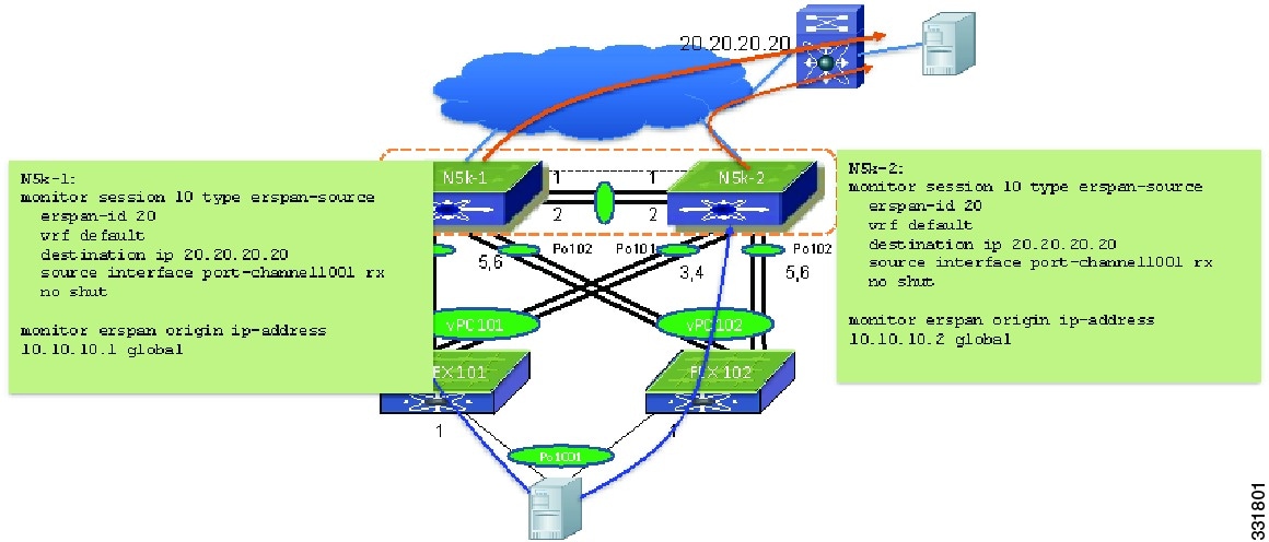
From the Cisco NX-OS 5.1(3)N1(1) release and later releases, the Cisco Nexus 5000 Series devices support ERSPAN source session. With ERSPAN, you can monitor and capture all the flows for the same vPC from one sniffer. The following example shows how to capture all the traffic flows from a host behind an Enhanced vPC.
Note
Figure 6-12 Monitoring the Traffic in Enhanced vPC
In the Enhanced vPC topology, a unicast and multicast flow can be sent to either one of two FEXs involved in the host vPC. The following example shows how to identify which path the traffic flow is forwarded to. In the following example po1001 is an Enhanced vPC host port channel consists of eth110/1/1 and eth111/1/1. The unicast flow from 30.30.1.2 to 30.30.3.2 is sent to FEX 111. Enter the command to determine which FEX interface from N5k-1 to FEX 111 is carrying the flow.
N5596-1# show port-channel load-balance forwarding-path interface po1001 Vlan 10 Src-ip
30.30.1.2 dst-ip 30.30.3.2 src-mac 0000.0100.1100 dst-mac 0000.0000.0b00
Missing params will be substituted by 0's.Load-balance Algorithm on FEX: source-dest-ipcrc8_hash: Not Used Outgoing port id: Ethernet111/1/1Param(s) used to calculate load-balance (Unknown unicast, multicast and broadcast packets):dst-mac: 0000.0000.0b00vlan id: 10This example shows FEX 110 and interface eth110/1/1 carries the multicast flow for Po1001:
N5596-1# show port-channel load-balance forwarding-path interface po1001 vlan 10 src-mac
0000.0100.1100 dst-mac 0100.5e01.010a src-ip 30.30.1.2 dst-ip 224.1.1.10
Missing params will be substituted by 0's.Load-balance Algorithm on FEX: source-dest-ipcrc8_hash: Not Used Outgoing port id: Ethernet110/1/1Param(s) used to calculate load-balance (Unknown unicast, multicast and broadcast packets):dst-ip: 224.1.1.10vlan id: 10N5596-1#