Cisco Nexus 5000 Series NX-OS Interfaces Configuration Guide, Release 5.2(1)N1(1)
Bias-Free Language
The documentation set for this product strives to use bias-free language. For the purposes of this documentation set, bias-free is defined as language that does not imply discrimination based on age, disability, gender, racial identity, ethnic identity, sexual orientation, socioeconomic status, and intersectionality. Exceptions may be present in the documentation due to language that is hardcoded in the user interfaces of the product software, language used based on RFP documentation, or language that is used by a referenced third-party product. Learn more about how Cisco is using Inclusive Language.
- Updated:
- July 13, 2012
Chapter: Configuring Layer 3 Interfaces
- Information About Layer 3 Interfaces
- Licensing Requirements for Layer 3 Interfaces
- Guidelines and Limitations for Layer 3 Interfaces
- Default Settings for Layer 3 Interfaces
- Configuring Layer 3 Interfaces
- Verifying the Layer 3 Interfaces Configuration
- Monitoring Layer 3 Interfaces
- Configuration Examples for Layer 3 Interfaces
- Related Documents for Layer 3 Interfaces
- MIBs for Layer 3 Interfaces
- Standards for Layer 3 Interfaces
Configuring Layer 3 Interfaces
This chapter contains the following sections:
- Information About Layer 3 Interfaces
- Licensing Requirements for Layer 3 Interfaces
- Guidelines and Limitations for Layer 3 Interfaces
- Default Settings for Layer 3 Interfaces
- Configuring Layer 3 Interfaces
- Verifying the Layer 3 Interfaces Configuration
- Monitoring Layer 3 Interfaces
- Configuration Examples for Layer 3 Interfaces
- Related Documents for Layer 3 Interfaces
- MIBs for Layer 3 Interfaces
- Standards for Layer 3 Interfaces
Information About Layer 3 Interfaces
Layer 3 interfaces forward packets to another device using static or dynamic routing protocols. You can use Layer 3 interfaces for IP routing and inter-VLAN routing of Layer 2 traffic.
- Routed Interfaces
- Subinterfaces
- VLAN Interfaces
- Loopback Interfaces
- Tunnel Interfaces
- IP Addressing Scheme with Private VLANs
Routed Interfaces
You can configure a port as a Layer 2 interface or a Layer 3 interface. A routed interface is a physical port that can route IP traffic to another device. A routed interface is a Layer 3 interface only and does not support Layer 2 protocols, such as the Spanning Tree Protocol (STP).
All Ethernet ports are switched interfaces by default. You can change this default behavior with the CLI setup script or through the system default switchport command.
You can assign an IP address to the port, enable routing, and assign routing protocol characteristics to this routed interface.
You can assign a static MAC address to a Layer 3 interface. For information on configuring MAC addresses, see the Layer 2 Switching Configuration Guide for your device.
You can also create a Layer 3 port channel from routed interfaces.
Subinterfaces
You can create virtual subinterfaces on a parent interface configured as a Layer 3 interface. A parent interface can be a physical port or a port channel.
Subinterfaces divide the parent interface into two or more virtual interfaces on which you can assign unique Layer 3 parameters such as IP addresses and dynamic routing protocols. The IP address for each subinterface should be in a different subnet from any other subinterface on the parent interface.
You create a subinterface with a name that consists of the parent interface name (for example, Ethernet 2/1) followed by a period and then by a number that is unique for that subinterface. For example, you could create a subinterface for Ethernet interface 2/1 named Ethernet 2/1.1 where .1 indicates the subinterface.
Cisco NX-OS enables subinterfaces when the parent interface is enabled. You can shut down a subinterface independent of shutting down the parent interface. If you shut down the parent interface, Cisco NX-OS shuts down all associated subinterfaces as well.
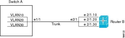
One use of subinterfaces is to provide unique Layer 3 interfaces to each VLAN that is supported by the parent interface. In this scenario, the parent interface connects to a Layer 2 trunking port on another device. You configure a subinterface and associate the subinterface to a VLAN ID using 802.1Q trunking.
The following figure shows a trunking port from a switch that connects to router B on interface E 2/1. This interface contains three subinterfaces that are associated with each of the three VLANs that are carried by the trunking port.
VLAN Interfaces
A VLAN interface or a switch virtual interface (SVI) is a virtual routed interface that connects a VLAN on the device to the Layer 3 router engine on the same device. Only one VLAN interface can be associated with a VLAN, but you need to configure a VLAN interface for a VLAN only when you want to route between VLANs or to provide IP host connectivity to the device through a virtual routing and forwarding (VRF) instance that is not the management VRF. When you enable VLAN interface creation, Cisco NX-OS creates a VLAN interface for the default VLAN (VLAN 1) to permit remote switch administration.
You must enable the VLAN network interface feature before you can configure it. The system automatically takes a checkpoint prior to disabling the feature, and you can roll back to this checkpoint. For information about rollbacks and checkpoints, see the System Management Configuration Guide for your device.
 Note | You cannot delete the VLAN interface for VLAN 1. |
You can route across VLAN interfaces to provide Layer 3 inter-VLAN routing by configuring a VLAN interface for each VLAN that you want to route traffic to and assigning an IP address on the VLAN interface. For more information on IP addresses and IP routing, see the Unicast Routing Configuration Guide for your device.
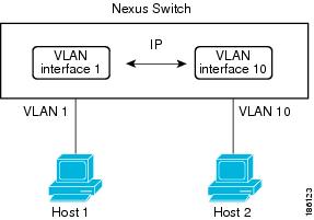
The following figure shows two hosts connected to two VLANs on a device. You can configure VLAN interfaces for each VLAN that allows Host 1 to communicate with Host 2 using IP routing between the VLANs. VLAN 1 communicates at Layer 3 over VLAN interface 1and VLAN 10 communicates at Layer 3 over VLAN interface 10.
Loopback Interfaces
A loopback interface is a virtual interface with a single endpoint that is always up. Any packet that is transmitted over a loopback interface is immediately received by this interface. Loopback interfaces emulate a physical interface.
You can use loopback interfaces for performance analysis, testing, and local communications. Loopback interfaces can act as a termination address for routing protocol sessions. This loopback configuration allows routing protocol sessions to stay up even if some of the outbound interfaces are down.
Tunnel Interfaces
Cisco NX-OS supports tunnel interfaces as IP tunnels. IP tunnels can encapsulate a same- layer or higher layer protocol and transport the result over IP through a tunnel that is created between two routers.
IP Addressing Scheme with Private VLANs
When you assign a separate VLAN to each customer, an inefficient IP addressing scheme is created as follows:
-
Assigning a block of addresses to a customer VLAN can result in unused IP addresses.
-
If the number of devices in the VLAN increases, the number of assigned addresses might not be large enough to accommodate them.
These problems are reduced by using private VLANs, where all members in the private VLAN share a common address space, which is allocated to the primary VLAN. Hosts are connected to secondary VLANs, and the DHCP server assigns them IP addresses from the block of addresses allocated to the primary VLAN. Subsequent IP addresses can be assigned to customer devices in different secondary VLANs, but in the same primary VLAN. When new devices are added, the DHCP server assigns them the next available address from a large pool of subnet addresses.
Licensing Requirements for Layer 3 Interfaces
This feature does not require a license. Any feature not included in a license package is bundled with the Cisco NX-OS system images and is provided at no extra charge to you. For a complete explanation of the Cisco NX-OS licensing scheme, see the Cisco NX-OS Licensing Guide.
Guidelines and Limitations for Layer 3 Interfaces
-
If you change a Layer 3 interface to a Layer 2 interface, Cisco NX-OS shuts down the interface, reenables the interface, and removes all configuration specific to Layer 3.
-
If you change a Layer 2 interface to a Layer 3 interface, Cisco NX-OS shuts down the interface, reenables the interface, and deletes all configuration specific to Layer 2.
Default Settings for Layer 3 Interfaces
The default setting for the Layer 3 Admin state is Shut.
Configuring Layer 3 Interfaces
Configuring a Routed Interface
This example shows how to configure an IPv4-routed Layer 3 interface:
switch# configure terminal
switch(config)# interface ethernet 2/1
switch(config-if)# no switchport
switch(config-if)# ip address 192.0.2.1/8
switch(config-if)# copy running-config startup-config
Configuring a Subinterface
| Command or Action | Purpose | |
|---|---|---|
| Step 1 | switch(config-if)# copy running-config startup-config | (Optional)
Saves the change persistently through reboots and restarts by copying the running configuration to the startup configuration. |
| Step 2 | switch(config)# interface ethernet slot/port.number | Enters interface configuration mode. The range for the slot is from 1 to 255. The range for the port is from 1 to 128. |
| Step 3 | switch(config-if)# [ip | ipv6] address ip-address/length | Configures an IP address for this interface. |
| Step 4 | switch(config-if)# encapsulation dot1Q vlan-id | Configures IEEE 802.1Q VLAN encapsulation on the subinterface. The range for the vlan-id is from 2 to 4093. |
| Step 5 | switch(config-if)# show interfaces | (Optional) Displays the Layer 3 interface statistics. |
| Step 6 | switch(config-if)# copy running-config startup-config | (Optional)
Saves the change persistently through reboots and restarts by copying the running configuration to the startup configuration. |
This example shows how to create a subinterface:
switch# configure terminal
switch(config)# interface ethernet 2/1
switch(config-if)# ip address 192.0.2.1/8
switch(config-if)# encapsulation dot1Q 33
switch(config-if)# copy running-config startup-config
Configuring the Bandwidth on an Interface
You can configure the bandwidth for a routed interface, port channel, or subinterface.
| Command or Action | Purpose | |
|---|---|---|
| Step 1 | switch# configure terminal |
Enters global configuration mode. |
| Step 2 | switch(config)# interface ethernet slot/port | Enters interface configuration mode. The range for the slot is from 1 to 255. The range for the port is from 1 to 128. |
| Step 3 | switch(conifg-if)# bandwidth [value | inherit [value]] | Configures the bandwidth parameter for a routed interface, port channel, or subinterface, as follows: |
| Step 4 | switch(config-if)# copy running-config startup-config | (Optional)
Saves the change persistently through reboots and restarts by copying the running configuration to the startup configuration. |
This example shows how to configure Ethernet interface 2/1 with a bandwidth value of 80000:
switch# configure terminal
switch(config)# interface ethernet 2/1
switch(config-if)# bandwidth 80000
switch(config-if)# copy running-config startup-config
Configuring a VLAN Interface
| Command or Action | Purpose | |
|---|---|---|
| Step 1 | switch# configure terminal |
Enters global configuration mode. |
| Step 2 | switch(config)# feature interface-vlan | Enables VLAN interface mode. |
| Step 3 | switch(config)# interface vlan number | Creates a VLAN interface. The number range is from 1 to 4094. |
| Step 4 | switch(config-if)# [ip | ipv6 ] address ip-address/length | Configures an IP address for this interface. |
| Step 5 | switch(config-if)# no shutdown | Brings the interface up administratively. |
| Step 6 | switch(config-if)# show interface vlan number | (Optional) Displays the VLAN interface statistics. The number range is from 1 to 4094. |
| Step 7 | switch(config-if)# copy running-config startup-config | (Optional)
Saves the change persistently through reboots and restarts by copying the running configuration to the startup configuration. |
This example shows how to create a VLAN interface:
switch# configure terminal
switch(config)# feature interface-vlan
switch(config)# interface vlan 10
switch(config-if)# ip address 192.0.2.1/8
switch(config-if)# copy running-config startup-config
Mapping Secondary VLANs to the Layer 3 VLAN Interface of a Primary VLAN
To map secondary VLANs to the Layer 3 VLAN interface of a primary VLAN to allow Layer 3 switching of private VLAN ingress traffic, perform this task:
| Command or Action | Purpose | |||
|---|---|---|---|---|
| Step 1 | Router(config)# interface-vlan primary_vlan_ID |
Enters interface configuration mode for the primary VLAN.
| ||
| Step 2 | Router(config-if)# private-vlan mapping {secondary_vlan_list | add secondary_vlan_list | remove secondary_vlan_list} |
Maps the secondary VLANs to the Layer 3 VLAN interface of a primary VLAN to allow Layer 3 switching of private VLAN ingress traffic. When you map secondary VLANs to the Layer 3 VLAN interface of a primary VLAN, note the following information:
| ||
| Step 3 | Router(config-if)# no private-vlan mapping |
Clears the mapping between the secondary VLANs and the primary VLAN. | ||
| Step 4 | Router(config-if)# end |
Exits configuration mode. | ||
| Step 5 | Router show interface private-vlan mapping |
Verifies the configuration. |
This example shows how to permit routing of secondary VLAN ingress traffic from private VLANs 303 through 307, 309, and 440 and verify the configuration:
Router# configure terminal
 Router(config)# interface vlan 202
 Router(config-if)# private-vlan mapping add 303-307,309,440
 Router(config-if)# end
 Router# show interfaces private-vlan mapping
 Interface Secondary VLAN Type
 --------- -------------- -----------------
 vlan202   303            community
 vlan202   304            community
 vlan202   305            community
 vlan202   306            community
 vlan202   307            community
 vlan202   309            community
 vlan202   440            isolated
 Router#
Configuring a Loopback Interface
Ensure that the IP address of the loopback interface is unique across all routers on the network.
| Command or Action | Purpose | |
|---|---|---|
| Step 1 | switch# configure terminal | Enters global configuration mode. |
| Step 2 | switch(config)# interface loopback instance | Creates a loopback interface. The instance range is from 0 to 1023. |
| Step 3 | switch(config-if)# [ip | ipv6 ] address ip-address/length | Configures an IP address for this interface. |
| Step 4 | switch(config-if)# show interface loopback instance | (Optional) Displays the loopback interface statistics. The instance range is from 0 to 1023. |
| Step 5 | switch(config-if)# copy running-config startup-config | (Optional)
Saves the change persistently through reboots and restarts by copying the running configuration to the startup configuration. |
This example shows how to create a loopback interface:
switch# configure terminal
switch(config)# interface loopback 0
switch(config-if)# ip address 192.0.2.100/8
switch(config-if)# copy running-config startup-config
Assigning an Interface to a VRF
Assign the IP address for a tunnel interface after you have configured the interface for a VRF.
| Command or Action | Purpose | |
|---|---|---|
| Step 1 | switch# configure terminal |
Enters global configuration mode. |
| Step 2 | switch(config)# interface interface-typenumber |
Enters interface configuration mode. |
| Step 3 | switch(conifg-if)#vrf member vrf-name |
Adds this interface to a VRF. |
| Step 4 | switch(config-if)# [ip | ipv6]ip-address/length |
Configures an IP address for this interface. You must do this step after you assign this interface to a VRF. |
| Step 5 | switch(config-if)# show vrf [vrf-name] interface interface-type number | (Optional)
Displays VRF information. |
| Step 6 | switch(config-if)# show interfaces | (Optional)
Displays the Layer 3 interface statistics. |
| Step 7 | switch(config-if)# copy running-config startup-config | (Optional)
Saves the change persistently through reboots and restarts by copying the running configuration to the startup configuration. |
This example shows how to add a Layer 3 interface to the VRF:
switch# configure terminal
switch(config)# interface loopback 0
switch(config-if)# vrf member RemoteOfficeVRF
switch(config-if)# ip address 209.0.2.1/16
switch(config-if)# copy running-config startup-config
Verifying the Layer 3 Interfaces Configuration
Use one of the following commands to verify the configuration:
|
Command |
Purpose |
|---|---|
|
show interface ethernet slot/port |
Displays the Layer 3 interface configuration, status, and counters (including the 5-minute exponentially decayed moving average of inbound and outbound packet and byte rates). |
|
show interface ethernet slot/port brief |
Displays the Layer 3 interface operational status. |
|
show interface ethernet slot/port capabilities |
Displays the Layer 3 interface capabilities, including port type, speed, and duplex. |
|
show interface ethernet slot/port description |
Displays the Layer 3 interface description. |
|
show interface ethernet slot/port status |
Displays the Layer 3 interface administrative status, port mode, speed, and duplex. |
|
show interface ethernet slot/port.number |
Displays the subinterface configuration, status, and counters (including the f-minute exponentially decayed moving average of inbound and outbound packet and byte rates). |
|
show interface port-channel channel-id.number |
Displays the port-channel subinterface configuration, status, and counters (including the 5-minute exponentially decayed moving average of inbound and outbound packet and byte rates). |
|
show interface loopback number |
Displays the loopback interface configuration, status, and counters. |
|
show interface loopback number brief |
Displays the loopback interface operational status. |
|
show interface loopback number description |
Displays the loopback interface description. |
|
show interface loopback number status |
Displays the loopback interface administrative status and protocol status. |
|
show interface vlan number |
Displays the VLAN interface configuration, status, and counters. |
|
show interface vlan number brief |
Displays the VLAN interface operational status. |
|
show interface vlan number description |
Displays the VLAN interface description. |
|
show interface vlan number private-vlan mapping |
Displays the VLAN interface private VLAN information. |
|
show interface vlan number status |
Displays the VLAN interface administrative status and protocol status. |
Monitoring Layer 3 Interfaces
Use one of the following commands to display statistics about the feature:
|
Command |
Purpose |
|---|---|
|
show interface ethernet slot/port counters |
Displays the Layer 3 interface statistics (unicast, multicast, and broadcast). |
|
show interface ethernet slot/port counters brief |
Displays the Layer 3 interface input and output counters. |
|
show interface ethernet slot/port counters detailed [all] |
Displays the Layer 3 interface statistics. You can optionally include all 32-bit and 64-bit packet and byte counters (including errors). |
|
show interface ethernet slot/port counters error |
Displays the Layer 3 interface input and output errors. |
|
show interface ethernet slot/port counters snmp |
Displays the Layer 3 interface counters reported by SNMP MIBs. You cannot clear these counters. |
|
show interface ethernet slot/port.number counters |
Displays the subinterface statistics (unicast, multicast, and broadcast). |
|
show interface port-channel channel-id.number counters |
Displays the port-channel subinterface statistics (unicast, multicast, and broadcast). |
|
show interface loopback number counters |
Displays the loopback interface input and output counters (unicast, multicast, and broadcast). |
|
show interface loopback number counters detailed [all] |
Displays the loopback interface statistics. You can optionally include all 32-bit and 64-bit packet and byte counters (including errors). |
|
show interface loopback number counters errors |
Displays the loopback interface input and output errors. |
|
show interface vlan number counters |
Displays the VLAN interface input and output counters (unicast, multicast, and broadcast). |
|
show interface vlan number counters detailed [all] |
Displays the VLAN interface statistics. You can optionally include all Layer 3 packet and byte counters (unicast and multicast). |
|
show interface vlan counters snmp |
Displays the VLAN interface counters reported by SNMP MIBs. You cannot clear these counters. |
Configuration Examples for Layer 3 Interfaces
switch# configuration terminal
switch(config)# interface ethernet 2/1.10
switch(config-if)# description Layer 3 for VLAN 10
switch(config-if)# encapsulation dot1q 10
switch(config-if)# ip address 192.0.2.1/8
switch(config-if)# copy running-config startup-config
switch# configuration terminal
switch(config)# interface vlan 100
switch(config-if)# no switchport

switch(config-if)# ipv6 address 33:0DB::2/8
switch(config-if)# copy running-config startup-config
switch# configuration terminal
switch(config)# interface loopback 3
switch(config-if)# no switchport
switch(config-if)# ip address 192.0.2.2/32
switch(config-if)# copy running-config startup-config
Related Documents for Layer 3 Interfaces
| Related Topics | Document Title |
|---|---|
Command syntax |
For details about command syntax, see the command reference for your device. |
IP |
“Configuring IP” chapter in the Unicast Routing Configuration Guide for your device. |
VLAN |
“Configuring VLANs” chapter in the Layer 2 Switching Configuration Guide for your device. |
MIBs for Layer 3 Interfaces
| MIB | MIB Link |
|---|---|
IF-MIB |
To locate and download MIBs, go to the following URL: http://www.cisco.com/public/sw-center/netmgmt/cmtk/mibs.shtml |
CISCO-IF-EXTENSION-MIB |
|
ETHERLIKE-MIB |
Standards for Layer 3 Interfaces
No new or modified standards are supported by this feature, and support for existing standards has not been modified by this feature.
 Feedback