Feedback
Contents
- Initial Switch Configuration
- Image Files on the Switch
- Starting the Switch
- Boot Sequence
- Console Settings
- Upgrading the Switch Software
- Downgrading from a Higher Release
- Configuration Prerequisites
- Initial Setup
- Preparing to Configure the Switch
- Default Login
- Configuring the Switch
- Changing the Initial Configuration
- Accessing the Switch
- Assigning a Switch Name
- Configuring Date and Time
- Configuring Time Zone
- Adjusting for Daylight Saving Time or Summer Time
- NTP Configuration
- About NTP
- NTP Configuration Guidelines
- Configuring NTP
- NTP CFS Distribution
- Enabling NTP Distribution
- Committing NTP Configuration Changes
- Discarding NTP Configuration Changes
- Releasing Fabric Session Lock
- Database Merge Guidelines
- NTP Session Status Verification
- Management Interface Configuration
- About the mgmt0 Interface
- Configuring the Management Interface
- Displaying Management Interface Configuration
- Shutting Down the Management Interface
- Displaying the Switch Configuration
- Saving a Configuration
- Clearing a Configuration
- Setting the Current Directory
- Displaying the Current Directory
- Listing the Files in a Directory
- Creating a Directory
- Deleting an Existing Directory
- Moving Files
- Copying Files
- Deleting Files
- Displaying File Contents
- Saving Command Output to a File
- Compressing and Uncompressing Files
Initial Switch Configuration
This chapter describes the command-line interface (CLI) and CLI command modes of Cisco Nexus 5000 Series switches. It includes the following sections:
- Image Files on the Switch
- Upgrading the Switch Software
- Downgrading from a Higher Release
- Accessing the Switch
- NTP Configuration
- Management Interface Configuration
Configuring the Switch
Image Files on the Switch
The Cisco Nexus 5000 Series switches have the following images:
BIOS and loader images combined in one file
Kickstart image
System image that includes a BIOS image that can be upgraded
The switch has flash memory that consists of two separate flash parts:
A 2 MB flash part holds two BIOS and loader images.
A 1 GB flash part holds configuration files, kickstart images, systems images, and other files.
The upgradeable BIOS and the golden BIOS are programmed onto the 2 MB flash part. You cannot upgrade the golden BIOS.
When you download a new pair of kickstart and system images, you also get a new BIOS image because it is included in the system image. You can use the install all command to upgrade the kickstart, system, and upgradeable BIOS images.
Boot Sequence
When the switch boots, the golden BIOS validates the checksum of the upgradeable BIOS. If the checksum is valid, then control is transferred to the upgradeable BIOS image. The upgradeable BIOS launches the kickstart image, which then launches the system image. If the checksum of the upgradeable BIOS is not valid, then the golden BIOS launches the kickstart image, which then launches the system image.
You can force the switch to bypass the upgradeable BIOS and use the golden BIOS instead. If you press Ctrl-Shift-6 within two seconds of when power is supplied to the switch, the golden BIOS will be used to launch the kickstart image, even if the checksum of the upgradeable BIOS is valid.
Note
When you press Ctrl-Shift-6, the console settings must be set to their defaults: 9600 baud, 8 data bits, no parity, and 1 stop bit.
Before the boot sequence starts, the BIOS performs internal tests on the switch. If the tests fail, then the loader does not gain control. Instead, the BIOS image retains control and prints a message to the console at 9600 baud every 30 seconds that indicates a failure.
The following figure shows the normal and recovery boot sequence.
For additional information, see Troubleshooting.
Console Settings
The loader, kickstart, and system images have the following factory default console settings:
These settings are stored on the switch, and all three images use the stored console settings.
To change a console setting, use the line console command in configuration mode. The following example configures a line console and sets the options for that terminal line:
switch# configure terminalswitch(config)# line consoleswitch(config-console)# databits 7switch(config-console)# exec-timeout 30switch(config-console)# parity evenswitch(config-console)# stopbits 2You cannot change the BIOS console settings. These are the same as the default console settings.
Upgrading the Switch Software
SUMMARY STEPS
Note
You must have the network-admin role before you can upgrade the software image on the switch.
You must log in to the switch on its console port connection.
To upgrade the software on the switch, follow these steps:
1. Log in to Cisco.com to access the Software Download Center. To log in to Cisco.com, go to the URL http://www.cisco.com/ and click Log In at the top of the page. Enter your Cisco username and password.
2. Access the Software Download Center using this URL: http://www.cisco.com/kobayashi/sw-center/index.shtml
3. Navigate to the software downloads for Cisco Nexus 5000 Series switches.
4. Read the release notes for the related image file.
5. Select and download the kickstart and system software files to a local server.
6. Ensure that the required space is available in the bootflash: directory for the image file(s) to be copied.
7. If you need more space on the active supervisor module bootflash, delete unnecessary files to make space available.
8. Copy the kickstart and system images to the switch bootflash using a transfer protocol. You can use ftp, tftp, scp, or sftp. The examples in this procedure use scp.
9. Install the new images, specifying the new image names that you downloaded in the previous step.
10. After the switch completes the installation, log in and verify that the switch is running the required software version.
DETAILED STEPS
Step 1 Log in to Cisco.com to access the Software Download Center. To log in to Cisco.com, go to the URL http://www.cisco.com/ and click Log In at the top of the page. Enter your Cisco username and password.
Note Unregistered Cisco.com users cannot access the links provided in this document.
Step 2 Access the Software Download Center using this URL: http://www.cisco.com/kobayashi/sw-center/index.shtml Step 3 Navigate to the software downloads for Cisco Nexus 5000 Series switches. You see links to the download images for the switch.
Step 4 Read the release notes for the related image file. Step 5 Select and download the kickstart and system software files to a local server. Step 6 Ensure that the required space is available in the bootflash: directory for the image file(s) to be copied.
Example:switch# dir bootflash:4681 Nov 24 02:43:52 2008 config13176836 Nov 24 07:19:36 2008 gdb.149152 Jan 12 18:38:36 2009 lost+found/310556 Dec 23 02:53:28 2008 n120058112 Nov 07 02:35:22 2008 n5000-uk9-kickstart.4.0.1a.N1.0.62.bin20217856 Jan 12 18:26:54 2009 n5000-uk9-kickstart.4.0.1a.N2.0.140.bin76930262 Nov 07 02:35:22 2008 n5000-uk9.4.0.1a.N1.0.62.bin103484727 Jan 12 18:29:08 2009 n5000-uk9.4.0.1a.N2.0.140.binUsage for bootflash://sup-local74934272 bytes used5550080 bytes free80484352 bytes total
Caution We recommend that you keep the kickstart and system image files for at least one previous software release to use if the new image files do not load successfully.
Step 7 If you need more space on the active supervisor module bootflash, delete unnecessary files to make space available.
Example:switch# delete bootflash:n5000-uk9-kickstart.4.0.1a.N1.0.62.binswitch# delete bootflash:n5000-uk9.4.0.1a.N1.0.62.binStep 8 Copy the kickstart and system images to the switch bootflash using a transfer protocol. You can use ftp, tftp, scp, or sftp. The examples in this procedure use scp.
Example:switch# copy scp://user@scpserver.cisco.com/downloads/n5000-uk9.4.1.3.N1.0.96.bin bootflash:n5000-uk9.4.1.3.N1.0.96.binswitch# copy scp://user@scpserver.cisco.com/downloads/n5000-uk9-kickstart.4.1.3.N1.0.96.bin bootflash:n5000-uk9-kickstart.4.1.3.N1.0.96.binStep 9 Install the new images, specifying the new image names that you downloaded in the previous step.
Example:switch# install all kickstart bootflash:n5000-uk9-kickstart.4.1.3.N1.0.96.bin system bootflash:n5000-uk9.4.1.3.N1.0.96.binThe install all command performs the following actions:
Performs compatibility checks (equivalent to the show incompatibility command) for the images that you have specified. If there are compatibility issues, an error message is displayed and the installation does not proceed.
Displays the compatibility check results and displays whether the installation is disruptive.
Provides a prompt to allow you to continue or abort the installation.
Caution After completing the installation, all traffic through the switch is disrupted while the switch reboots.
Updates the boot variables to reference the specified images and saves the configuration to the startup configuration file.
Step 10 After the switch completes the installation, log in and verify that the switch is running the required software version.
Example:switch# show versionCisco Nexus Operating System (NX-OS) SoftwareTAC support: http://www.cisco.com/tacCopyright (c) 2002-2009, Cisco Systems, Inc. All rights reserved.The copyrights to certain works contained herein are owned byother third parties and are used and distributed under license.Some parts of this software are covered under the GNU PublicLicense. A copy of the license is available athttp://www.gnu.org/licenses/gpl.html.SoftwareBIOS: version 1.2.0loader: version N/Akickstart: version 4.1(3)N1(1) [build 4.1(3)N1(0.96)]system: version 4.1(3)N1(1) [build 4.1(3)N1(0.96)]BIOS compile time: 06/19/08kickstart image file is: bootflash:/n5000-uk9-kickstart.4.1.3.N1.0.96.binkickstart compile time: 7/14/2009 4:00:00 [07/14/2009 04:27:38]system image file is: bootflash:/n5000-uk9.4.1.3.N1.0.96.binsystem compile time: 7/14/2009 4:00:00 [07/14/2009 05:20:12]Hardwarecisco Nexus5020 Chassis ("40x10GE/Supervisor")Intel(R) Celeron(R) M CPU with 2074240 kB of memory.Processor Board ID JAB1232002FDevice name: switchbootflash: 1003520 kBKernel uptime is 13 day(s), 23 hour(s), 25 minute(s), 5 second(s)Last reset at 720833 usecs after Tue Jul 14 11:18:32 2009Reason: Reset by installerSystem version: 4.1(3)N1(0.96)Service:pluginCore Plugin, Ethernet Plugin
Downgrading from a Higher Release
SUMMARY STEPSThe procedure to downgrade the switch is identical to a switch upgrade, except that the image files to be loaded are for an earlier release than the image currently running on the switch.
Note
Prior to downgrading to a specific release, check the release notes for the current release installed on the switch, to ensure that your hardware is compatible with the specific release. There are special caveats you must be aware of before you downgrade the switch software to a 4.0(0)-based release. See the Cisco Nexus 5000 Series and Cisco Nexus 2000 Series Release Notes for details.
To downgrade the software on the switch, follow these steps:
1. Locate the image files you will use for the downgrade by entering the dir bootflash: command.
3. After the switch completes the installation, log in and verify that the switch is running the required software version.
DETAILED STEPS
Initial Configuration
Configuration Prerequisites
SUMMARY STEPSThe following procedure is a review of the tasks you should have completed during hardware installation. These tasks must be completed before you can configure the switch.
Before you can configure a switch, follow these steps:
1. Verify the following physical connections for the new Cisco Nexus 5000 Series switch:
2. Verify that the default console port parameters are identical to those of the computer terminal (or terminal server) attached to the switch console port:
DETAILED STEPS
Step 1 Verify the following physical connections for the new Cisco Nexus 5000 Series switch:
The console port is physically connected to a computer terminal (or terminal server).
The management Ethernet port (mgmt0) is connected to an external hub, switch, or router.
Refer to the Cisco Nexus 5000 Series Hardware Installation Guide (for the required product) for more information.
Tip Save the host ID information for future use (for example, to enable licensed features). The host ID information is provided in the Proof of Purchase document that accompanies the switch.
Step 2 Verify that the default console port parameters are identical to those of the computer terminal (or terminal server) attached to the switch console port:
Initial Setup
The first time that you access a switch in the Cisco Nexus 5000 Series, it runs a setup program that prompts you for the IP address and other configuration information necessary for the switch to communicate over the Ethernet interface. This information is required to configure and manage the switch.
Note
The IP address can only be configured from the CLI. When the switch powers up for the first time, you should assign the IP address. After you perform this step, the Cisco MDS 9000 Family Fabric Manager can reach the switch through the console port.
Preparing to Configure the Switch
Before you configure Cisco Nexus 5000 Series switch for the first time, you need the following information:
Administrator password.
Note
If a password is weak (short, easy-to-decipher), your password configuration is rejected. Be sure to configure a strong password.
If you are using an IPv4 address for the management interface, you need the following information:
SSH service on the switch (optional).
To enable this service, select the type of SSH key (dsa/rsa/rsa1) and number of SSH key bits (768 to 2048).
NTP server IPv4 address (optional).
SNMP community string (optional).
Switch name (optional).
This is your switch prompt.
An additional login account and password (optional).
Note
If you are using IPv4, be sure to configure the IPv4 route, the IPv4 default network address, and the IPv4 default gateway address to enable SNMP access.
Default Login
The switch has the network administrator as a default user (admin). You cannot change the default user at any time.
There is no default password so you must explicitly configure a strong password. If a password is trivial (short, easy-to-decipher), your password configuration is rejected. Be sure to configure a strong password. If you configure and subsequently forget this new password, you have the option to recover this password.
Note
If you enter the write erase command and reload the switch, you must reconfigure the default user (admin) password using the setup procedure.
Configuring the Switch
SUMMARY STEPSThis section describes how to initially configure the switch.
Note
Press Ctrl-C at any prompt to skip the remaining configuration options and proceed with what you have configured up to that point. Entering the new password for the administrator is a requirement and cannot be skipped.
Tip
If you do not want to answer a previously configured question, or if you want to skip answers to any questions, press Enter. If a default answer is not available (for example, switch name), the switch uses what was previously configured and skips to the next question.
To configure the switch for first time, follow these steps:
1. Ensure that the switch is on. Switches in the Cisco Nexus 5000 Series boot automatically.
2. Enter the new password for the administrator.
3. Enter yes to enter the setup mode.
4. Enter the new password for the administrator (admin is the default).
5. Enter yes (no is the default) to create additional accounts.
6. Enter yes (yes is the default) to create an SNMP read-only community string.
7. Enter a name for the switch.
8. Enter yes (yes is the default) to configure out-of-band management and enter the mgmt0 IPv4 address.
9. Enter yes (yes is the default) to configure the IPv4 default gateway (recommended) and enter the IPv4 address for the default gateway.
10. Enter yes (yes is the default) to enable the Telnet service.
11. Enter yes (no is the default) to enable the SSH service.
12. Enter yes (no is the default) to configure the NTP server and enter the IPv4 address for the NTP server.
13. Enter yes (yes is the default) to configure basic Fibre Channel configurations.
14. Enter shut (shut is the default) to configure the default Fibre Channel switch port interface to the shut (disabled) state.
15. Enter on (on is the default) to configure the switch port trunk mode.
16. Enter permit (deny is the default) to deny a default zone policy configuration.
17. Enter yes (no is the default) to enable a full zone set distribution.
18. You see the new configuration. Review and edit the configuration that you have just entered. Enter no (no is the default) if you are satisfied with the configuration.
19. Enter yes (yes is default) to use and save this configuration:
DETAILED STEPS
Step 1 Ensure that the switch is on. Switches in the Cisco Nexus 5000 Series boot automatically. Step 2 Enter the new password for the administrator.
Example:Enter the password for admin: <password>
Tip If a password is weak (short, easy-to-decipher), your password configuration is rejected. Be sure to configure a strong password. Passwords are case-sensitive.
Step 3 Enter yes to enter the setup mode.
Example:This setup utility will guide you through the basic configuration ofthe system. Setup configures only enough connectivity for managementof the system.*Note: setup is mainly used for configuring the system initially,when no configuration is present. So setup always assumes systemdefaults and not the current system configuration values.Press Enter at anytime to skip a dialog. Use ctrl-c at anytimeto skip the remaining dialogs.Would you like to enter the basic configuration dialog (yes/no): yesThe setup utility guides you through the basic configuration process. Press Ctrl-C at any prompt to end the configuration process.
Step 4 Enter the new password for the administrator (admin is the default).
Example:Enter the password for admin: adminStep 5 Enter yes (no is the default) to create additional accounts.
Example:Create another login account (yes/no) [n]: yesWhile configuring your initial setup, you can create an additional user account (in the network-admin role) besides the administrator's account.
Step 6 Enter yes (yes is the default) to create an SNMP read-only community string.
Example:Configure read-only SNMP community string (yes/no) [n]:yesSNMP community string: snmp_communityStep 7 Enter a name for the switch.
Note The switch name is limited to 32 alphanumeric characters. The default name is "switch".
Example:Enter the switch name: switch_nameStep 8 Enter yes (yes is the default) to configure out-of-band management and enter the mgmt0 IPv4 address.
Example:Continue with Out-of-band (mgmt0) management configuration? [yes/no]: yesMgmt0 IPv4 address: ip_addressStep 9 Enter yes (yes is the default) to configure the IPv4 default gateway (recommended) and enter the IPv4 address for the default gateway.
Example:Configure the default-gateway: (yes/no) [y]: yesIPv4 address of the default-gateway: default_gatewayStep 10 Enter yes (yes is the default) to enable the Telnet service.
Example:Enable the telnet service? (yes/no) [y]: yesStep 11 Enter yes (no is the default) to enable the SSH service.
Example:Enabled SSH service? (yes/no) [n]: yes
Step 12 Enter yes (no is the default) to configure the NTP server and enter the IPv4 address for the NTP server.
Example:Configure NTP server? (yes/no) [n]: yesNTP server IP address: ntp_server_IP_addressStep 13 Enter yes (yes is the default) to configure basic Fibre Channel configurations.
Example:Enter basic FC configurations (yes/no) [n]: yesStep 14 Enter shut (shut is the default) to configure the default Fibre Channel switch port interface to the shut (disabled) state.
Example:Configure default physical FC switchport interface state (shut/noshut) [shut]: shutStep 15 Enter on (on is the default) to configure the switch port trunk mode.
Example:Configure default physical FC switchport trunk mode (on/off/auto) [on]: onStep 16 Enter permit (deny is the default) to deny a default zone policy configuration.
Example:Configure default zone policy (permit/deny) [deny]: permitPermits traffic flow to all members of the default zone.
Note If you are executing the setup script after entering a write erase command, you explicitly must change the default zone policy to permit for VSAN 1 after finishing the script using the following command:
Configure read-only SNMP community string (yes/no) [n]: zone default-zone permit vsan 1Step 17 Enter yes (no is the default) to enable a full zone set distribution.
Example:Enable full zoneset distribution (yes/no) [n]: yesOverrides the switch-wide default for the full zone set distribution feature.
Step 18 You see the new configuration. Review and edit the configuration that you have just entered. Enter no (no is the default) if you are satisfied with the configuration.
Example:The following configuration will be applied:username admin password <user-password> role network-adminsnmp-server community snmp_community roswitchname switchfeature telnetssh key dsa 768 forcefeature sshsystem default switchport shutdown sansystem default switchport trunk mode onsystem default zone default-zone permitsystem default zone distribute fullWould you like to edit the configuration? (yes/no) [n]: noStep 19 Enter yes (yes is default) to use and save this configuration:
Example:Use this configuration and save it? (yes/no) [y]: yes
Caution If you do not save the configuration at this point, none of your changes are updated the next time the switch is rebooted. Type yes to save the new configuration. This operation ensures that the kickstart and system images are also automatically configured.
Changing the Initial Configuration
To make changes to the initial configuration at a later time, enter the setup command in EXEC mode:
switch# setup---- Basic System Configuration Dialog ----This setup utility will guide you through the basic configuration ofthe system. Setup configures only enough connectivity for managementof the system.*Note: setup is mainly used for configuring the system initially,when no configuration is present. So setup always assumes systemdefaults and not the current system configuration values.Press Enter at anytime to skip a dialog. Use ctrl-c at anytimeto skip the remaining dialogs.Would you like to enter the basic configuration dialog (yes/no): yesThe setup utility guides you through the basic configuration process.
Accessing the Switch
After the initial configuration, you can access the switch in a number of ways:
Serial console access—You can use a serial port connection to access the CLI.
Out-of-band access—You can use Telnet or SSH to access a Cisco Nexus 5000 Series switch or use the Cisco Data Center Network Manager (DCNM) or the Cisco MDS 9000 Fabric Manager application to connect to the switch using SNMP and XML.
Additional Switch Configuration
Assigning a Switch Name
SUMMARY STEPSEach switch in the network requires a unique name. You can assign names to easily identify the switch by its physical location, its network association, or the organization to which it is deployed. The assigned name is displayed in the command-line prompt. The switch name is limited to 20 alphanumeric characters.
Note
This guide refers to a switch in the Cisco Nexus 5000 Series switch as switch , and it uses the switch# prompt.
To change the name of the switch, perform this task:
2. switch(config)# [no] switchname name
DETAILED STEPS
Command or Action Purpose Step 1 switch# configure terminal
Enters configuration mode.
Step 2 switch(config)# [no] switchname name
Changes the switch name prompt to the specified name. The no command reverts the switch name prompt to its default.
Configuring Date and Time
SUMMARY STEPSThe Cisco Nexus 5000 Series switches use Universal Coordinated Time (UTC), which is the same as Greenwich Mean Time (GMT). To change the default time on the switch, perform this task:
1. switch# clock set HH:MM:SS DD Month YYYY
DETAILED STEPS
Command or Action Purpose Step 1 switch# clock set HH:MM:SS DD Month YYYY
Sets the default time on the switch. HH represents hours in 24-hour time (15 for 3 P.M.), MM is minutes (58), SS is seconds (09), DD is the date (29), Month is the month in words (February), and YYYY is the year (2008).
Configuring Time Zone
SUMMARY STEPSThe Cisco Nexus 5000 Series switches use Universal Coordinated Time (UTC), which is the same as Greenwich Mean Time (GMT). You can specify a time zone for the switch. To specify the local time without the daylight saving time feature, perform this task:
2. switch(config)# clock timezone timezone hours_offset minutes_offset
DETAILED STEPS
Command or Action Purpose Step 1 switch# configure terminal
Enters configuration mode.
Step 2 switch(config)# clock timezone timezone hours_offset minutes_offset
Sets the time zone. timezone is the three letter time zone (PST for Pacific Standard), the hours offset from UTC (-8 for the PST offset), and minutes offset (needed for time zones such as Newfoundland Standard (NST) or India Standard (IST)).
Step 3 switch(config)# exit
Returns to EXEC mode.
Step 4 switch# show clock
Verifies the time zone configuration.
Step 5 switch# show run
Displays changes made to the time zone configuration along with other configuration information.
Adjusting for Daylight Saving Time or Summer Time
SUMMARY STEPSYou can configure your switch to adjust for daylight saving time (or summer time). By default, Cisco NX-OS does not automatically adjust for daylight saving time. You must manually configure the switch to adjust to the daylight saving time.
For example, following U.S. standards (defined by the Energy Policy Act of 2005), you can have the switch advance the clock one hour at 2:00 a.m. on the second Sunday in March and move back the clock one hour at 2:00 a.m. on the first Sunday in November. You can also explicitly specify the start and end dates and times and whether or not the time adjustment recurs every year.
To enable the daylight saving time clock adjustment, perform this task:
2. switch(config)# clock summer-time timezone start_week start_day start_month start_time end_week end_day end_month end_time offset
3. switch(config)# no clock summer-time
5. switch# show running-config | include summer-time
DETAILED STEPS
Command or Action Purpose Step 1 switch# configure terminal
Enters configuration mode.
Step 2 switch(config)# clock summer-time timezone start_week start_day start_month start_time end_week end_day end_month end_time offset
Sets the daylight savings time for a specified time zone.
The start and end values are as follows:
Week ranging from 1 through 5
Day ranging from Sunday through Saturday
Month ranging from January through December
The daylight offset ranges from 1 through 1440 minutes, which are added to the start time and deleted time from the end time.
Step 3 switch(config)# no clock summer-time
Disables the daylight saving time adjustment feature.
Step 4 switch(config)# exit
Returns to EXEC mode.
Step 5 switch# show running-config | include summer-time
Verifies the time zone configuration.
The following example adjusts the daylight savings time for the U.S. Pacific daylight time by 60 minutes starting the second Sunday in March at 2 a.m. and ending the first Sunday in November at 2 a.m:
switch# configure terminalswitch(config)# clock summer-time PDT 1 Sunday March 02:00 5 Sunday November 02:00 60NTP Configuration
A Network Time Protocol (NTP) server provides a precise time source (radio clock or atomic clock) to synchronize the system clocks of network devices. NTP uses User Datagram Protocol (UDP) on port 123 as its transport layer. An NTP server receives its time from a reference time source, such as a radio clock or atomic clock, attached to the server. NTP distributes this time across the network. All NTP communications use Universal Time Coordinated (UTC).
- About NTP
- NTP Configuration Guidelines
- Configuring NTP
- NTP CFS Distribution
- Enabling NTP Distribution
- Committing NTP Configuration Changes
- Discarding NTP Configuration Changes
- Releasing Fabric Session Lock
- Database Merge Guidelines
- NTP Session Status Verification
About NTP
In a large enterprise network, having one time standard for all network devices is critical for management reporting and event logging functions when trying to correlate interacting events logged across multiple devices. Many enterprise customers with extremely mission-critical networks maintain their own stratum-11 NTP source.
Time synchronization happens when several frames are exchanged between clients and servers. The switches in client mode know the address of one or more NTP servers. The servers act as the time source and receive client synchronization requests.
By configuring an IP address as a peer, the switch will obtain and provide time as required. The peer is capable of providing time on its own and is capable of having a server configured. If both these instances point to different time servers, your NTP service is more reliable. Even if the active server link is lost, you can still maintain the right time due to the presence of the peer.
If an active server fails, a configured peer helps in providing the NTP time. Provide a direct NTP server association and configure a peer to ensure backup support if the active server fails.
If you only configure a peer, the most accurate peer takes on the role of the NTP server and the other peer(s) acts as a peer(s).
NTP Configuration Guidelines
The following guidelines apply to all NTP configurations:
You should have a peer association with another switch only when you are sure that your clock is reliable (which means that you are a client of a reliable NTP server).
A peer configured alone takes on the role of a server and should be used as backup. If you have two servers, then you can have several switches point to one server, and the remaining switches to the other server. You would configure peer association between these two sets, which forces the clock to be more reliable.
If you only have one server, it is better for all the switches to have a client association with that server.
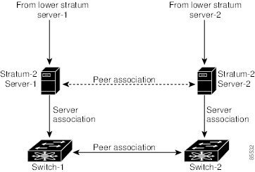
Not even a server down time will affect well-configured switches in the network. The following figure displays a network with two NTP stratum 2 servers and two switches.
In this configuration, the switches were configured as follows:
Stratum 2 Server 1
Switch 1 IPv4 address–10.10.10.1
Switch 1 NTP configuration commands
switch(config)# ntp server 10.10.10.10switch(config)# ntp peer 10.10.10.2Switch 2 IPv4 address–10.10.10.2
Switch 2 NTP configuration commands
switch(config)# ntp server 10.10.10.9switch(config)# ntp peer 10.10.10.1Configuring NTP
SUMMARY STEPSYou can configure NTP using either IPv4 addresses, IPv6 addresses, or Domain Name Services (DNS) names. To configure NTP associations, perform this task:
2. switch(config)# ntp server {ip-address | ipv6-address | dns-name}
3. switch(config)# ntp peer {ip-address | ipv6-address | dns-name}
4. (Optional) switch# copy running-config startup-config
5. (Optional) switch# show ntp peers
DETAILED STEPS
Command or Action Purpose Step 1 switch# configure terminal
Enters configuration mode.
Step 2 switch(config)# ntp server {ip-address | ipv6-address | dns-name}
Forms an association with a server.
Step 3 switch(config)# ntp peer {ip-address | ipv6-address | dns-name}
Forms an association with a peer. You can specify multiple associations.
Step 4 switch# copy running-config startup-config
(Optional) Saves your configuration changes to NVRAM.
Step 5 switch# show ntp peers
(Optional) Displays the configured server and peer associations.
NTP CFS Distribution
You can enable NTP fabric distribution for all Cisco Nexus 5000 Series switches in a fabric using the Cisco Fabric Services (CFS). When you perform NTP configurations, and distribution is enabled, the entire server or peer configuration is distributed to all the switches in the fabric.
You automatically acquire a fabric-wide lock when you enter the first configuration command after you enabled distribution in a switch.The NTP application uses an effective and pending database model to store or commit the commands based on your configuration. You changes are stored in the pending database and committed to the effective database.
For additional information, see Information About CFS in the Cisco Nexus 5000 Series NX-OS System Management Configuration Guide.
- Enabling NTP Distribution
- Committing NTP Configuration Changes
- Discarding NTP Configuration Changes
- Releasing Fabric Session Lock
- Database Merge Guidelines
- NTP Session Status Verification
Enabling NTP Distribution
SUMMARY STEPS2. switch(config)# ntp distribute
3. switch(config)# no ntp distribute
DETAILED STEPS
Command or Action Purpose Step 1 switch# configure terminal
Enters configuration mode.
Step 2 switch(config)# ntp distribute
Enables NTP configuration distribution to all switches in the fabric. Acquires a fabric lock and stores all future configuration changes in the pending database.
Step 3 switch(config)# no ntp distribute
Disables (default) NTP configuration distribution to all switches in the fabric.
Committing NTP Configuration Changes
SUMMARY STEPSWhen you commit the NTP configuration changes, the effective database is overwritten by the configuration changes in the pending database and all the switches in the fabric receive the same configuration. When you commit the NTP configuration changes without implementing the session feature, the NTP configurations are distributed to all the switches in the fabric.
To commit the NTP configuration changes, perform this task:
DETAILED STEPS
Command or Action Purpose Step 1 switch# configure terminal
Enters configuration mode.
Step 2 switch(config)# ntp commit
Distributes the NTP configuration changes to all switches in the fabric and releases the lock. Overwrites the effective database with the changes made to the pending database.
Discarding NTP Configuration Changes
SUMMARY STEPSAfter making the configuration changes, you can choose to discard the changes or to commit them. In either case, the lock is released.
To discard NTP configuration changes, perform this task:
DETAILED STEPS
Command or Action Purpose Step 1 switch# configure terminal
Enters configuration mode.
Step 2 switch(config)# ntp abort
Discards the NTP configuration changes in the pending database and releases the fabric lock.
Releasing Fabric Session Lock
If you have performed an NTP fabric task and have forgotten to release the lock by either committing or discarding the changes, an administrator can release the lock from any switch in the fabric. If the administrator performs this task, your changes to the pending database are discarded and the fabric lock is released.
The changes are only available in the volatile directory and are subject to being discarded if the switch is restarted.
To use administrative privileges and release a locked NTP session, use the clear ntp session command.
switch# clear ntp sessionDatabase Merge Guidelines
When merging two fabrics, follow these guidelines:
Be aware that the merge is a union of the existing and the received database in each switch in the fabric.
Do not configure an IP address as a server on one switch and as a peer on another switch. The merge can fail if this configuration exists.
Verify that the union of the databases does not exceed the maximum limit of 64.
Management Interface Configuration
The management interface on the switch allows multiple simultaneous Telnet, SSH, or SNMP sessions. You can remotely configure the switch through the management interface (mgmt0), but first you must configure some IP parameters so that the switch is reachable. You can manually configure the management interface from the CLI through the console port.
- About the mgmt0 Interface
- Configuring the Management Interface
- Displaying Management Interface Configuration
- Shutting Down the Management Interface
About the mgmt0 Interface
The mgmt0 interface on a Cisco Nexus 5000 Series switch provides out-of-band management, which enables you to manage the switch by its IPv4 or IPv6 address. The mgmt0 interface is a 10/100/1000 Ethernet port.
Note
Before you begin to configure the management interface manually, obtain the switch’s IP address and subnet mask. Also make sure that the console cable is connected to the console port.
Configuring the Management Interface
SUMMARY STEPS2. switch(config)# interface mgmt 0
3. Configure the IP address for IPv4 or IPv6:
4. switch(config-if)# no shutdown
6. switch(config)# vrf context management
7. Configure the IP address (IPv4 or IPv6) for the next hop:
9. (Optional) switch# copy running-config startup-config
DETAILED STEPS
Step 1 switch# configure terminal
Enters configuration mode.
Step 2 switch(config)# interface mgmt 0
Selects the management Ethernet interface on the switch and enters interface configuration submode.
Step 3 Configure the IP address for IPv4 or IPv6:
Step 4 switch(config-if)# no shutdown
Enables the interface.
Step 5 switch(config-if)# exit
Returns to configuration mode.
Step 6 switch(config)# vrf context management
Enters VRF context management configuration mode.
Step 7 Configure the IP address (IPv4 or IPv6) for the next hop:
Step 8 switch(config-vrf)# exit
Returns to EXEC mode.
Step 9 (Optional) switch# copy running-config startup-config
Saves your configuration changes to the file system.
Displaying Management Interface Configuration
To display the management interface configuration, use the show interface mgmt 0 command.
switch# show interface mgmt0mgmt0 is upHardware is GigabitEthernet, address is 000d.ec8f.cb00 (bia 000d.ec8f.cb00)Internet Address is 172.16.131.202/24MTU 1500 bytes, BW 0 Kbit, DLY 0 usec,reliability 255/255, txload 1/255, rxload 1/255Encapsulation ARPAfull-duplex, 1000 Mb/sInput flow-control is off, output flow-control is off8540 packets input, 2835036 bytes5202 multicast frames, 0 compressed0 input errors, 0 frame, 0 overrun, 0 fifo570 packets output, 85555 bytes0 underrun, 0 output errors, 0 collisions0 fifo, 0 carrier errorsShutting Down the Management Interface
To shut down the management interface (mgmt0), you use the shutdown command. A system prompt requests you confirm your action before it executes the command. You can use the force option to bypass this confirmation.
The following example shuts down the interface without using the force option:
switch# configure terminalswitch(config)# interface mgmt 0switch(config-if)# shutdownShutting down this interface will drop all telnet sessions.Do you wish to continue (y/n)? yThe following example shuts down the interface using the force option:
switch# configure terminalswitch(config)# interface mgmt 0switch(config-if)# shutdown forceManaging the Switch Configuration
Displaying the Switch Configuration
You can view the ASCII form of the configuration file when required. To view the current configuration tree from the EXEC prompt, enter the show running-config command. If the running configuration is different from the startup configuration, enter the show startup-config command to view the ASCII version of the current startup configuration that was used to boot the switch if a copy running-config startup-config command was not entered after the reboot. Use the show startup-config command to view the contents of the current startup configuration.
You can also gather specific information on the entire switch configuration by entering the relevant show commands. Configurations are displayed based on a specified feature, interface, module, or VSAN. Available show commands for each feature are briefly described in this section and listed at the end of each chapter.
Clearing a Configuration
Use the write erase command to clear a startup configuration. Once this command is executed, the switch’s startup configuration reverts to factory defaults. The running configuration is not affected.
Caution
The write erase command erases the entire startup configuration with the exception of any configuration that affects the loader functionality.
The write erase boot command only erases the configuration that affects the loader functionality. The loader functionality configuration includes the boot variables and the mgmt0 IP configuration information (IP address, netmask, and default gateway).
switch# write erase bootThis command will erase the boot variables and the IP configuration of interface mgmt 0.
Using Switch File Systems
Setting the Current Directory
The cd command changes the current directory level to a specified directory level. The CLI defaults to the volatile: file system. This command expects a directory name input.
Any file saved in the volatile: file system is erased when the switch reboots.
The syntax for this command is cd directory name.
This command exchanges the current directory to the root directory on the bootflash: file system:
switch# cd bootflash:This example changes the current directory to a mystorage directory that resides in the current directory:
switch# cd mystorageListing the Files in a Directory
The dir command displays the contents of the current directory or the specified directory. The syntax for this command is dir directory or dir filename.
This example shows how to list the files on the default volatile file system:
switch# dir volatile:Usage for volatile://sup-local0 bytes used20971520 bytes free20971520 bytes totalCreating a Directory
The mkdir command creates a directory at the current directory level or at a specified directory level.
The syntax for this command is mkdir name.
This example creates a directory called test in the bootflash directory.
switch# mkdir bootflash:testThis example creates a directory called test in the current directory.
switch# mkdir testDeleting an Existing Directory
The rmdir command deletes an existing directory at the current directory level or at a specified directory level. The directory must be empty to be deleted.
The syntax for this command is rmdir name.
This example deletes the directory called test in the bootflash directory:
switch# rmdir bootflash:testThis is a directory. Do you want to continue (y/n)? [y] yThe delete command can also delete empty and nonempty directories. When you enter this command, a warning is displayed to confirm your intention to delete the directory.
This example deletes the directory called test in the current directory:
switch# delete testThis is a directory. Do you want to continue (y/n)? [y] yIf the current directory is bootflash:mydir, this command deletes the bootflash:mydir/test directory.
Moving Files
The move command removes a file from the source directory and places it in the destination directory.
Caution
If a file with the same name already exists in the destination directory, that file is overwritten by the moved file.
This example moves the file called samplefile from the root directory to the mystorage directory:
switch# move bootflash:samplefile bootflash:mystorage/samplefileThis example moves a file from the current directory level:
switch# move samplefile mystorage/samplefileIf the current directory is bootflash:mydir, this command moves bootflash:mydir/samplefile to bootflash:mydir/mystorage/samplefile.
Copying Files
The copy command copies a file between file systems within a switch.
Note
Use the dir command to ensure that enough space is available in the target file system. If enough space is not available, use the delete command to remove unneeded files.
This example copies the file called samplefile from the root directory to the mystorage directory:
switch# copy bootflash:samplefile bootflash:mystorage/samplefileThis example copies a file from the current directory level:
switch# copy samplefile mystorage/samplefileIf the current directory is bootflash:mydir, this command copies bootflash:mydir/samplefile to bootflash:mydir/mystorage/samplefile.
Deleting Files
The delete command deletes a specified file or the specified directory and all its contents.
This example shows how to delete a file from the current working directory:
switch# delete dns_config.cfgThis example deletes the entire bootflash: directory and all its contents:
switch# delete bootflash:my-dir
Caution
If you specify a directory, the delete command deletes the entire directory and all its contents.
Saving Command Output to a File
You can force all screen output to go to a file by appending > filename to any command. For example, enter show interface > Samplefile at the EXEC mode switch prompt to save the interface configuration to Samplefile which is a file created at the same directory level. At the EXEC mode switch prompt, enter a dir command to view all files in this directory, including the recently saved Samplefile.
Compressing and Uncompressing Files
The gzip command compresses (zips) the specified file using LZ77 coding.
This example directs the output of the show tech-support command to a file (Samplefile), and then zips the file and displays the difference in the space used up in the volatile directory:
switch# show tech-support > SamplefileBuilding Configuration ...switch# dir1525859 Jul 04 00:51:03 2003 SamplefileUsage for volatile://1527808 bytes used19443712 bytes free20971520 bytes totalswitch# gzip volatile:Samplefileswitch# dir266069 Jul 04 00:51:03 2003 Samplefile.gzUsage for volatile://266240 bytes used20705280 bytes free20971520 bytes totalThe gunzip command uncompresses (unzips) LZ77 coded files.
This example unzips the file that was compressed in the previous example:
switch# gunzip Samplefileswitch# dir1525859 Jul 04 00:51:03 2003 SamplefileUsage for volatile://1527808 bytes used19443712 bytes free20971520 bytes total1 NTP uses a hierarchical, layered system of levels of clock sources. Each level of this hierarchy is termed a stratum. Stratum 0 devices are atomic clocks, GPS clocks, or other radio clocks and are typically not directly connected to the network. Stratum 1 devices are directly attached to a Stratum 0 device as well as to the network and are referred to as time servers.