Cisco Nexus 1000V Interface Configuration Guide, Release 4.0(4)SV1(1)
Bias-Free Language
The documentation set for this product strives to use bias-free language. For the purposes of this documentation set, bias-free is defined as language that does not imply discrimination based on age, disability, gender, racial identity, ethnic identity, sexual orientation, socioeconomic status, and intersectionality. Exceptions may be present in the documentation due to language that is hardcoded in the user interfaces of the product software, language used based on RFP documentation, or language that is used by a referenced third-party product. Learn more about how Cisco is using Inclusive Language.
- Updated:
- May 21, 2009
Chapter: Configuring a Layer 2 Interface
Configuring Layer 2 Interfaces
Use this section to configure Layer 2 switching ports as access or trunk ports. Trunks carry the traffic of multiple VLANs over a single link and allow you to extend VLANs across an entire network. All Layer 2 switching ports maintain media access control (MAC) address tables.
This chapter includes the following topics:
•![]() Prerequisites for VLAN Trunking
Prerequisites for VLAN Trunking
•![]() Configuring Access and Trunk Interfaces
Configuring Access and Trunk Interfaces
•![]() Verifying Interface Configuration
Verifying Interface Configuration
•![]() Displaying and Clearing Statistics
Displaying and Clearing Statistics
•![]() Access and Trunk Port Mode Example Configurations
Access and Trunk Port Mode Example Configurations

Note ![]() For information about configuring a SPAN destination interface, see the document,
For information about configuring a SPAN destination interface, see the document,
Cisco Nexus 1000V System Management Configuration Guide, Release 4.0(4)SV1(1).
Note ![]() for information about VLANs, MAC address tables, and private VLANs, see the document,
for information about VLANs, MAC address tables, and private VLANs, see the document,
Cisco Nexus 1000V Layer 2 Switching Configuration Guide, Release 4.0(4)SV1(1).
Access and Trunk Interfaces
This section includes the following topics:
•![]() Information About Access and Trunk Interfaces
Information About Access and Trunk Interfaces
Information About Access and Trunk Interfaces
A Layer 2 port can be configured as an access or a trunk port as follows:
•![]() An access port can have only one VLAN configured on that port; it can carry traffic for only one VLAN.
An access port can have only one VLAN configured on that port; it can carry traffic for only one VLAN.
•![]() A trunk port can have two or more VLANs configured on that port; it can carry traffic for several VLANs simultaneously.
A trunk port can have two or more VLANs configured on that port; it can carry traffic for several VLANs simultaneously.
By default, all ports on the Cisco Nexus 1000V are Layer 2 ports. You can change the default port mode. See the Cisco Nexus 1000V Getting Started Guide, Release 4.0(4)SV1(1) for information about setting the default port mode.
Figure 3-1 show how you can use trunk ports in the network. The trunk port carries traffic for two or more VLANs.
Figure 3-1 Trunk and Access Ports and VLAN Traffic
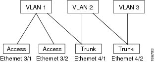
In order to correctly deliver the traffic on a trunk port with several VLANs, the device uses the IEEE 802.1Q encapsulation, or tagging, method (see the "IEEE 802.1Q Encapsulation" section for more information).
To optimize the performance on access ports, you can configure the port as a host port. Once the port is configured as a host port, it is automatically set as an access port, and channel grouping is disabled. Use the host designation to decrease the time that it takes the designated port to begin to forward packets.
If an access port receives a packet with an 802.1Q tag in the header other than the access VLAN value, that port drops the packet without learning its MAC source address.
A Layer 2 interface can function as either an access port or a trunk port; it cannot function as both port types simultaneously.
IEEE 802.1Q Encapsulation
A trunk is a point-to-point link between the switch and another networking device. Trunks carry the traffic of multiple VLANs over a single link and allow you to extend VLANs across an entire network.
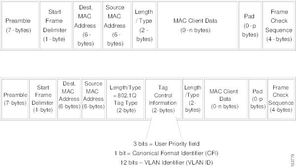
To correctly deliver the traffic on a trunk port with several VLANs, the device uses the IEEE 802.1Q encapsulation, or tagging, method that uses a tag that is inserted into the frame header (see Figure 3-2). This tag carries information about the specific VLAN to which the frame and packet belong. This method allows packets that are encapsulated for several different VLANs to traverse the same port and maintain traffic separation between the VLANs. Also, the encapsulated VLAN tag allows the trunk to move traffic end-to-end through the network on the same VLAN.
Figure 3-2 Header Without and With 802.1Q Tag
High Availability
The software supports high availability for Layer 2 ports.
Prerequisites for VLAN Trunking
•![]() You are logged inn to the CLI.
You are logged inn to the CLI.
Guidelines and Limitations
The following configuration guidelines and restrictions apply when using 802.1Q trunks and impose some limitations on the trunking strategy for a network. Consider these restrictions when using 802.1Q trunks:
•![]() Do not connect devices with access links because access links may partition a VLAN.
Do not connect devices with access links because access links may partition a VLAN.
•![]() When connecting Cisco switches through an 802.1Q trunk, make sure that the native VLAN for an 802.1Q trunk is the same on both ends of the trunk link. If the native VLAN on one end of the trunk is different from the native VLAN on the other end, spanning tree loops might result.
When connecting Cisco switches through an 802.1Q trunk, make sure that the native VLAN for an 802.1Q trunk is the same on both ends of the trunk link. If the native VLAN on one end of the trunk is different from the native VLAN on the other end, spanning tree loops might result.
•![]() You can group trunk ports into port channel groups, but all trunks in the group must have the same configuration. When a group is first created, all ports follow the parameters set for the first port to be added to the group. If you change the configuration of one of these parameters, the device propagates that setting to all ports in the group, such as the allowed VLANs and the trunk status. For example, if one port in a port group ceases to be a trunk, all ports cease to be trunks.
You can group trunk ports into port channel groups, but all trunks in the group must have the same configuration. When a group is first created, all ports follow the parameters set for the first port to be added to the group. If you change the configuration of one of these parameters, the device propagates that setting to all ports in the group, such as the allowed VLANs and the trunk status. For example, if one port in a port group ceases to be a trunk, all ports cease to be trunks.
•![]() If you try to enable 802.1X on a trunk port, an error message appears, and 802.1X is not enabled.
If you try to enable 802.1X on a trunk port, an error message appears, and 802.1X is not enabled.
•![]() If you try to change the mode of an 802.1X-enabled port to trunk, the port mode is not changed.
If you try to change the mode of an 802.1X-enabled port to trunk, the port mode is not changed.
Configuring Access and Trunk Interfaces
This section includes the following topics:
•![]() Configuring a LAN Interface as a Layer 2 Access Port
Configuring a LAN Interface as a Layer 2 Access Port
•![]() Configuring Access Host Ports
Configuring Access Host Ports
•![]() Configuring the Native VLAN for 802.1Q Trunking Ports
Configuring the Native VLAN for 802.1Q Trunking Ports
•![]() Configuring the Allowed VLANs for Trunking Ports
Configuring the Allowed VLANs for Trunking Ports
•![]() Configuring the Device to Tag Native VLAN Traffic
Configuring the Device to Tag Native VLAN Traffic
Note ![]() Be aware that the Cisco Nexus 1000V commands may differ from the Cisco IOS commands.
Be aware that the Cisco Nexus 1000V commands may differ from the Cisco IOS commands.
Configuring a LAN Interface as a Layer 2 Access Port
Use this procedure to configure a Layer 2 port as an access port.
BEFORE YOU BEGIN
•![]() Ensure that you are configuring a Layer 2 interface.
Ensure that you are configuring a Layer 2 interface.
•![]() The interface can be either Ethernet or vEthernet.
The interface can be either Ethernet or vEthernet.
•![]() An access port transmits packets on only one, untagged VLAN. You specify which VLAN traffic that the interface carries, which becomes the access VLAN. If you do not specify a VLAN for an access port, that interface carries traffic only on the default VLAN. The default VLAN is VLAN1.
An access port transmits packets on only one, untagged VLAN. You specify which VLAN traffic that the interface carries, which becomes the access VLAN. If you do not specify a VLAN for an access port, that interface carries traffic only on the default VLAN. The default VLAN is VLAN1.
•![]() The VLAN must exist before you can specify that VLAN as an access VLAN. The system shuts down an access port that is assigned to an access VLAN that does not exist.
The VLAN must exist before you can specify that VLAN as an access VLAN. The system shuts down an access port that is assigned to an access VLAN that does not exist.
SUMMARY STEPS
1. ![]() config t
config t
2. ![]() interface {{type slot/port} | {port-channel number}}
interface {{type slot/port} | {port-channel number}}
3. ![]() switchport mode {access | trunk}
switchport mode {access | trunk}
4. ![]() switchport access vlan vlan-id
switchport access vlan vlan-id
5. ![]() exit
exit
6. ![]() show interface
show interface
7. ![]() copy running-config startup-config
copy running-config startup-config
DETAILED STEPS
This example shows how to set Ethernet 3/1 as a Layer 2 access port that carries traffic for VLAN 5 only:
n1000v# config t
n1000v(config)# interface ethernet 3/1
n1000v(config-if)# switchport mode access
n1000v(config-if)# switchport access vlan 5
n1000v(config-if)#
Configuring Access Host Ports
Use this procedure to optimize the performance of access ports that are connected to end stations by simultaneously setting that port as an access port.
BEFORE YOU BEGIN
Before beginning this procedure, you must know or do the following:
•![]() Ensure that you are configuring the correct interface to an interface that is an end station.
Ensure that you are configuring the correct interface to an interface that is an end station.
•![]() You should apply the switchport host command only to interfaces connected to an end station.
You should apply the switchport host command only to interfaces connected to an end station.
•![]() An access host port handles the STP like an edge port and immediately moves to the forwarding state without passing through the blocking and learning states.
An access host port handles the STP like an edge port and immediately moves to the forwarding state without passing through the blocking and learning states.
•![]() Configuring an interface as an access host port also disables port channeling on that interface.
Configuring an interface as an access host port also disables port channeling on that interface.
Note ![]() See Chapter 5, "Configuring Port Channels" for information about port channel interfaces.
See Chapter 5, "Configuring Port Channels" for information about port channel interfaces.
•![]() The interface can be either Ethernet or vEthernet.
The interface can be either Ethernet or vEthernet.
SUMMARY STEPS
1. ![]() config t
config t
2. ![]() interface type slot/port
interface type slot/port
3. ![]() switchport host
switchport host
4. ![]() exit
exit
5. ![]() show interface
show interface
6. ![]() copy running-config startup-config
copy running-config startup-config
DETAILED STEPS
This example shows how to set Ethernet 3/1 as a Layer 2 access port with PortFast enabled and port channel disabled:
n1000v# config t
n1000v(config)# interface ethernet 3/1
n1000v(config-if)# switchport host
n1000v(config-if)#
Configuring Trunk Ports
Use this procedure to configure a Layer 2 port as a trunk port.
BEFORE YOU BEGIN
•![]() Before you configure a trunk port, ensure that you are configuring a Layer 2 interface.
Before you configure a trunk port, ensure that you are configuring a Layer 2 interface.
•![]() The interface can be either Ethernet or vEthernet.
The interface can be either Ethernet or vEthernet.
•![]() A trunk port transmits untagged packets for one VLAN plus encapsulated, tagged, packets for multiple VLANs. (See the "IEEE 802.1Q Encapsulation" section for information about encapsulation.)
A trunk port transmits untagged packets for one VLAN plus encapsulated, tagged, packets for multiple VLANs. (See the "IEEE 802.1Q Encapsulation" section for information about encapsulation.)
•![]() The device supports 802.1Q encapsulation only.
The device supports 802.1Q encapsulation only.
SUMMARY STEPS
1. ![]() config t
config t
2. ![]() interface {type slot/port | port-channel number}
interface {type slot/port | port-channel number}
3. ![]() switchport mode {access | trunk}
switchport mode {access | trunk}
4. ![]() exit
exit
5. ![]() show interface
show interface
6. ![]() copy running-config startup-config
copy running-config startup-config
DETAILED STEPS
This example shows how to set Ethernet 3/1 as a Layer 2 trunk port:
n1000v# config t
n1000v(config)# interface ethernet 3/1
n1000v(config-if)# switchport mode trunk
n1000v(config-if)#
Configuring the Native VLAN for 802.1Q Trunking Ports
Use this procedure to configure the native VLAN for 802.1Q trunk ports. If you do not configure this parameter, the trunk port uses the default VLAN as the native VLAN ID.
SUMMARY STEPS
1. ![]() config t
config t
2. ![]() interface {type slot/port | port-channel number}
interface {type slot/port | port-channel number}
3. ![]() switchport trunk native vlan vlan-id
switchport trunk native vlan vlan-id
4. ![]() exit
exit
5. ![]() show vlan
show vlan
6. ![]() copy running-config startup-config
copy running-config startup-config
DETAILED STEPS
This example shows how to set the native VLAN for the Ethernet 3/1, Layer 2 trunk port to VLAN 5:
n1000v# config t
n1000v(config)# interface ethernet 3/1
n1000v(config-if)# switchport trunk native vlan 5
n1000v(config-if)#
Configuring the Allowed VLANs for Trunking Ports
Use this procedure to specify the IDs for the VLANs that are allowed on the specific trunk port.
BEFORE YOU BEGIN
•![]() Before you configure the allowed VLANs for the specified trunk ports, ensure that you are configuring the correct interfaces and that the interfaces are trunks.
Before you configure the allowed VLANs for the specified trunk ports, ensure that you are configuring the correct interfaces and that the interfaces are trunks.
SUMMARY STEPS
1. ![]() config t
config t
2. ![]() interface {ethernet slot/port | port-channel number}
interface {ethernet slot/port | port-channel number}
3. ![]() switchport trunk allowed vlan {vlan-list | all | none | [add | except | | remove {vlan-list}]}
switchport trunk allowed vlan {vlan-list | all | none | [add | except | | remove {vlan-list}]}
4. ![]() exit
exit
5. ![]() show vlan
show vlan
6. ![]() copy running-config startup-config
copy running-config startup-config
DETAILED STEPS
This example shows how to add VLANs 15 to 20 to the list of allowed VLANs on the Ethernet 3/1, Layer 2 trunk port:
n1000v# config t
n1000v(config)# interface ethernet 3/1
n1000v(config-if)# switchport trunk allowed vlan 15-20
n1000v(config-if)#
Configuring the Device to Tag Native VLAN Traffic
Use this procedure, when working with 802.1Q trunked interfaces, to maintain the tagging for all packets that enter with a tag that matches the native VLAN ID. Untagged traffic is dropped (you will still carry control traffic on that interface).
BEFORE YOU BEGIN
•![]() The vlan dot1q tag native global command changes the behavior of all native VLAN ID interfaces on all trunks on the device.
The vlan dot1q tag native global command changes the behavior of all native VLAN ID interfaces on all trunks on the device.
•![]() This feature applies to the entire device; you cannot apply it to selected VLANs on a device.
This feature applies to the entire device; you cannot apply it to selected VLANs on a device.
Note ![]() If you enable 802.1Q tagging on one device and disable it on another device, all traffic is dropped on the device with this feature disabled. You must configure this feature identically on each device.
If you enable 802.1Q tagging on one device and disable it on another device, all traffic is dropped on the device with this feature disabled. You must configure this feature identically on each device.
SUMMARY STEPS
1. ![]() config t
config t
2. ![]() vlan dot1q tag native
vlan dot1q tag native
3. ![]() exit
exit
4. ![]() show vlan
show vlan
5. ![]() copy running-config startup-config
copy running-config startup-config
DETAILED STEPS
This example shows how to change the behavior of the native VLAN on an 802.1Q trunked interface to maintain the tagged packets and drop all untagged traffic (except control traffic):
n1000v# config t
n1000v(config)# vlan dot1q tag native
n1000v#
Verifying Interface Configuration
To display access and trunk interface configuration information, use one of the following commands:
Displaying and Clearing Statistics
To display access and trunk interface configuration information, use one of the following commands:
Access and Trunk Port Mode Example Configurations
The following example shows how to configure a Layer 2 access interface and assign the access VLAN for that interface:
n1000v# configure terminal
n1000v(config)# interface ethernet 2/30
n1000v(config-if)# switchport
n1000v(config-if)# switchport mode access
n1000v(config-if)# switchport access vlan 5
n1000v(config-if)#
The following example shows how to configure a Layer 2 trunk interface, assign the native VLAN and the allowed VLANs, and configure the device to tag the native VLAN traffic on the trunk interface:
n1000v# configure terminal
n1000v(config)# interface ethernet 2/35
n1000v(config-if)# switchport
n1000v(config-if)# switchport mode trunk
n1000v(config-if)# switchport trunk native vlan 10
n1000v(config-if)# switchport trunk allowed vlan 5, 10
n1000v(config-if)# exit
n1000v(config)# vlan dot1q tag native
n1000v(config)#
Default Settings
The following table lists the default settings for device access and trunk port mode parameters.
|
|
|
|---|---|
Switchport mode |
Access |
Allowed VLANs |
1 to 3967, 4048 to 4094 |
Access VLAN ID |
VLAN1 |
Native VLAN ID |
VLAN1 |
Native VLAN ID tagging |
Disabled |
Administrative state |
Shut |
Additional References
For additional information related to implementing access and trunk port modes, see the following sections:
Related Documents
Standards
|
|
|
|---|---|
No new or modified standards are supported by this feature, and support for existing standards has not been modified by this feature. |
— |
 Feedback