Cisco Fabric Manager Inter-VSAN Routing Configuration Guide
Bias-Free Language
The documentation set for this product strives to use bias-free language. For the purposes of this documentation set, bias-free is defined as language that does not imply discrimination based on age, disability, gender, racial identity, ethnic identity, sexual orientation, socioeconomic status, and intersectionality. Exceptions may be present in the documentation due to language that is hardcoded in the user interfaces of the product software, language used based on RFP documentation, or language that is used by a referenced third-party product. Learn more about how Cisco is using Inclusive Language.
- Updated:
- August 20, 2009
Chapter: Advanced Inter-VSAN Routing Configuration
Advanced Inter-VSAN Routing Configuration
This chapter provides advanced configuration information and instructions. Before setting up advanced IVR configurations, see Chapter 1, "Basic Inter-VSAN Routing Configuration" which includes basic configuration instructions and descriptions of IVR features, limits, and terminology.
This chapter includes the following sections:
•![]() Advanced IVR Configuration Task List
Advanced IVR Configuration Task List
•![]() IVR Without IVR NAT or Auto Topology
IVR Without IVR NAT or Auto Topology
•![]() Manually Configuring and Activating an IVR Topology
Manually Configuring and Activating an IVR Topology
•![]() Working With Existing IVR Topologies
Working With Existing IVR Topologies
•![]() Advanced IVR Zones and IVR Zone Sets
Advanced IVR Zones and IVR Zone Sets
Advanced IVR Configuration Task List
To configure an advanced IVR topology in a SAN fabric, follow these steps:
|
|
|
|
|---|---|---|
Step 1 |
Determine whether or not to use IVR Network Address Translation (NAT). |
See "IVR Network Address Translation" section on page 1-4 and "IVR NAT Requirements and Guidelines" section on page 1-8. |
Step 2 |
If you do not plan to use IVR NAT, verify that unique domain IDs are configured in all switches and VSANs participating in IVR. |
See Domain ID Guidelines. |
Step 3 |
Enable IVR in the border switches. |
See Configuring IVR and IVR Zones Using the IVR Zone Wizard, page 1-6 |
Step 4 |
Configure the service group as required. |
See IVR Service Groups. |
Step 5 |
Configure the IVR distribution as required. |
|
Step 6 |
Configure the IVR topology, either manually or automatically. |
SeeManually Configuring and Activating an IVR Topology and Basic IVR Configuration, page 1-5. |
Step 7 |
Create and activate IVR zone sets in all of the IVR-enabled border switches, either manually or using fabric distribution. |
Advanced IVR Configuration
This section includes instructions on advanced IVR configurations. It includes the following topics:
IVR Service Groups
In a complex network topology, you might only have a few IVR-enabled VSANs. To reduce the amount of traffic to non-IVR-enabled VSANs, you can configure service groups that restrict the traffic to the IVR-enabled VSANs. A maximum of 16 IVR service groups are allowed in a network. When a new IVR-enabled switch is added to the network, you must update the service groups to include the new VSANs.
This section includes the following information on service groups:
•![]() Configuring IVR Service Groups
Configuring IVR Service Groups
Service Group Guidelines
IVR service group guidelines are listed below:
•![]() If you use service groups with IVR Auto topology, you should enable IVR and configure your service groups first, then distribute them with CFS before setting the IVR topology in Auto mode.
If you use service groups with IVR Auto topology, you should enable IVR and configure your service groups first, then distribute them with CFS before setting the IVR topology in Auto mode.
•![]() The CFS distribution is restricted within the service group only when the IVR VSAN topology is in Auto mode. See the "IVR VSAN Topology" section on page 1-5.
The CFS distribution is restricted within the service group only when the IVR VSAN topology is in Auto mode. See the "IVR VSAN Topology" section on page 1-5.
•![]() You can configure as many as 16 service groups in a network.
You can configure as many as 16 service groups in a network.
•![]() When a new IVR-enabled switch is added to the network, you must update the service group to include the new VSANs.
When a new IVR-enabled switch is added to the network, you must update the service group to include the new VSANs.
•![]() The same VSAN and AFID combination cannot be a member of more than one service group otherwise a CFS merge will fail.
The same VSAN and AFID combination cannot be a member of more than one service group otherwise a CFS merge will fail.
•![]() The total number of AFID and VSAN combinations in all the service groups combined cannot exceed 128. The maximum number of AFID and VSAN combinations in a single service group is 128.
The total number of AFID and VSAN combinations in all the service groups combined cannot exceed 128. The maximum number of AFID and VSAN combinations in a single service group is 128.
•![]() The IVR service group configuration is distributed in all IVR-enabled switches. IVR data traffic between two end devices belonging to a service group stays within that service group. For example, two members (for example, pWWN 1 and pWWN 2) cannot communicate if they belong to the same IVR zone and they belong to different service groups.
The IVR service group configuration is distributed in all IVR-enabled switches. IVR data traffic between two end devices belonging to a service group stays within that service group. For example, two members (for example, pWWN 1 and pWWN 2) cannot communicate if they belong to the same IVR zone and they belong to different service groups.
•![]() During a CFS merge, service groups with the same name would be merged, as long as there are no conflicts with other service groups.
During a CFS merge, service groups with the same name would be merged, as long as there are no conflicts with other service groups.
•![]() If the total number of service groups exceeds 16 during a CFS merge, the CFS merge fails.
If the total number of service groups exceeds 16 during a CFS merge, the CFS merge fails.
•![]() CFS distributes service group configuration information to all reachable SANs. If you do not enable CFS distribution, you must ensure that the service group configuration is the same on all IVR-enabled switches in all VSANs.
CFS distributes service group configuration information to all reachable SANs. If you do not enable CFS distribution, you must ensure that the service group configuration is the same on all IVR-enabled switches in all VSANs.
•![]() IVR end devices belonging to an IVR service group are not exported to any AFID or VSAN outside of its service group.
IVR end devices belonging to an IVR service group are not exported to any AFID or VSAN outside of its service group.
•![]() When at least one service group is defined and an IVR zone member does not belong to the service group, that IVR zone member is not able to communicate with any other device.
When at least one service group is defined and an IVR zone member does not belong to the service group, that IVR zone member is not able to communicate with any other device.
•![]() The default service group ID is zero (0).
The default service group ID is zero (0).
Default Service Group
All AFID and VSAN combinations that are part of an IVR VSAN topology but are not part of any user-defined service group are members of the default service group. The identifier of the default service group is 0.
By default, IVR communication is permitted between members of the default service group. You can change the default policy to deny. To change the default policy, see the "Configuring IVR Service Groups" procedure. The default policy is not part of ASCII configuration.
Service Group Activation
A configured service group must be activated. Like zone set activation or VSAN topology activation, the activation of a configured service group replaces the currently active service group, if any, with the configured one. There is only one configured service group database and one active service group database. Each of these databases can have up to 16 service groups.
Configuring IVR Service Groups
To configure an IVR service group using Fabric Manager, follow these steps:
Step 1 ![]() Expand All VSANs and then select IVR in the Logical Domains pane.
Expand All VSANs and then select IVR in the Logical Domains pane.
You see the IVR configuration in the Information pane shown in Figure 2-1.
Figure 2-1 IVR Routing Configuration Control Tab
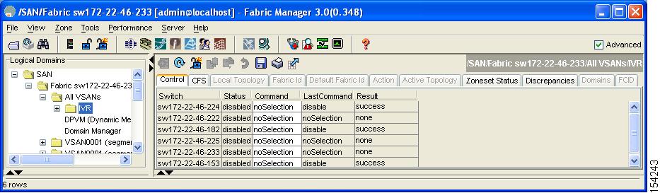
Step 2 ![]() Click the Service Group tab to display the existing service groups.
Click the Service Group tab to display the existing service groups.
Step 3 ![]() Click the Create Row icon to make a new service group.
Click the Create Row icon to make a new service group.
You see the service group dialog box.
Step 4 ![]() Check the switch check box for each switch involved in IVR.
Check the switch check box for each switch involved in IVR.
Step 5 ![]() Complete the Name field for the service group and fill in the Fabric ID field for this entry.
Complete the Name field for the service group and fill in the Fabric ID field for this entry.
Step 6 ![]() Enter a comma-separated list of VSAN IDs in the VSAN List text box.
Enter a comma-separated list of VSAN IDs in the VSAN List text box.
Step 7 ![]() Click Create to create this entry or click Cancel to discard all changes.
Click Create to create this entry or click Cancel to discard all changes.
Step 8 ![]() Repeat Step 1 through Step 7 for all switches and AFIDs associated with your IVR topology.
Repeat Step 1 through Step 7 for all switches and AFIDs associated with your IVR topology.
Autonomous Fabric IDs
The autonomous fabric ID (AFID) distinguishes segmented VSANS (for example, two VSANs that are logically and physically separate but have the same VSAN number). Cisco Fabric Manager Release 4.2(1) supports AFIDs 1 through 64. AFIDs are used in conjunction with Auto mode to allow segmented VSANs in the IVR VSAN topology database.
This section includes the following information about AFIDs:
•![]() Autonomous Fabric ID Guidelines
Autonomous Fabric ID Guidelines
Autonomous Fabric ID Guidelines
You can configure AFIDs individually for VSANs, or you can set the default AFIDs for all VSANs on a switch. If you configure an individual AFID for a subset of the VSANs on a switch that has a default AFID, that subset uses the configured AFID while all other VSANs on that switch use the default AFID.
You can only use an AFID configuration when the VSAN topology is in Auto mode. In a manually configured VSAN topology mode, the AFIDs are specified in the VSAN topology configuration itself and a separate AFID configuration is not needed.

Note ![]() Two VSANs with the same VSAN number but different AFIDs are counted as two VSANs out of the total 128 VSANs allowed in the fabric.
Two VSANs with the same VSAN number but different AFIDs are counted as two VSANs out of the total 128 VSANs allowed in the fabric.
When devices attached to multiple switches belong to one VSAN, they can not communicate with each other by configuring the regular zone set because the AFIDs are different. You can consider that the different AFIDs are different fabrics; therefore the three switches represent three separate fabrics.
If we specify the IVR VSAN topology as shown in Example 2-1, IVR will set up the connection between the devices across the switches even though they have the same VSAN.
Example 2-1 IVR VSAN Topology With the Same VSAN
switch# show ivr vsan-topology
AFID SWITCH WWN Active Cfg. VSANS
-----------------------------------------------------
1 20:00:00:0d:ec:27:6b:c0 yes yes 1
2 20:00:00:0d:ec:27:6c:00 yes yes 1
3 20:00:00:0d:ec:27:6c:40 yes yes 1
Total: 3 entries in active and configured IVR VSAN-Topology
Configuring Default AFIDs
To configure default AFIDs using Fabric Manager, follow these steps:
Step 1 ![]() Expand All VSANs and then select IVR in the Logical Domains pane.
Expand All VSANs and then select IVR in the Logical Domains pane.
You see the IVR configuration in the Information pane.
Step 2 ![]() Click the Default Fabric ID tab to display the existing default AFIDs.
Click the Default Fabric ID tab to display the existing default AFIDs.
Step 3 ![]() Click the Create Row icon to create a default AFID.
Click the Create Row icon to create a default AFID.
Step 4 ![]() Check the check boxes next to each switch involved in IVR that you want to use this default AFID.
Check the check boxes next to each switch involved in IVR that you want to use this default AFID.
Step 5 ![]() Provide a name for each SwitchWWN and set the default Fabric ID.
Provide a name for each SwitchWWN and set the default Fabric ID.
Step 6 ![]() Click Create to create this entry.
Click Create to create this entry.
Step 7 ![]() Repeat Step 1 through Step 6 for all default AFIDs that you want to configure in your IVR topology.
Repeat Step 1 through Step 6 for all default AFIDs that you want to configure in your IVR topology.
Configuring Individual AFIDs
To configure individual AFIDs using Fabric Manager, follow these steps:
Step 1 ![]() Expand All VSANs and then select IVR in the Logical Domains pane.
Expand All VSANs and then select IVR in the Logical Domains pane.
You see the IVR configuration in the Information pane.
Figure 2-2 Fabric ID Tab
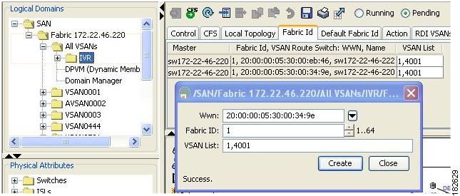
Step 2 ![]() Click the Fabric ID tab to display the existing AFIDs (see Figure 2-2).
Click the Fabric ID tab to display the existing AFIDs (see Figure 2-2).
Step 3 ![]() Click the Create Row icon to create an AFID.
Click the Create Row icon to create an AFID.
Step 4 ![]() Check the check box next to each switch involved in IVR that you want to use this default AFID.
Check the check box next to each switch involved in IVR that you want to use this default AFID.
Step 5 ![]() Provide a name for each SwitchWWN and set the Fabric ID.
Provide a name for each SwitchWWN and set the Fabric ID.
Step 6 ![]() Enter a comma-separated list of VSAN IDs in the VSAN List text box.
Enter a comma-separated list of VSAN IDs in the VSAN List text box.
Step 7 ![]() Click Create to create this entry.
Click Create to create this entry.
Step 8 ![]() Repeat Step 1 through Step 6 for all switches and AFIDs you want to configure in your IVR topology.
Repeat Step 1 through Step 6 for all switches and AFIDs you want to configure in your IVR topology.
IVR Without IVR NAT or Auto Topology
This section includes the following sections on IVR Without IVR NAT or Auto Topology
•![]() IVR Without IVR NAT or Auto Topology Guidelines
IVR Without IVR NAT or Auto Topology Guidelines
•![]() Manually Configuring an IVR Topology
Manually Configuring an IVR Topology
IVR Without IVR NAT or Auto Topology Guidelines
Before configuring an IVR SAN fabric without IVR in NAT mode or IVR topology in Auto mode, consider the following general guidelines:
•![]() Acquire a mandatory Enterprise License Package or SAN-EXTENSION license package and one active IPS card for this feature.
Acquire a mandatory Enterprise License Package or SAN-EXTENSION license package and one active IPS card for this feature.
•![]() If you change an FSPF link cost, ensure that the FSPF path distance (the sum of the link costs on the path) of any IVR path is less than 30,000.
If you change an FSPF link cost, ensure that the FSPF path distance (the sum of the link costs on the path) of any IVR path is less than 30,000.
•![]() IVR-enabled VSANs can be configured when an interop mode is enabled or disabled.
IVR-enabled VSANs can be configured when an interop mode is enabled or disabled.
This section also includes the following:
Domain ID Guidelines
Before configuring domain IDs, consider the following guidelines:
•![]() Configure unique domain IDs across all VSANs and switches participating in IVR operations if you are not using IVR NAT. The following switches participate in IVR operations:
Configure unique domain IDs across all VSANs and switches participating in IVR operations if you are not using IVR NAT. The following switches participate in IVR operations:
–![]() All edge switches in the edge VSANs (source and destination)
All edge switches in the edge VSANs (source and destination)
–![]() All switches in transit VSANs
All switches in transit VSANs
•![]() Minimize the number of switches that require a domain ID assignment. This ensures minimum traffic disruption.
Minimize the number of switches that require a domain ID assignment. This ensures minimum traffic disruption.
•![]() Minimize the coordination between interconnected VSANs when configuring the SAN for the first time as well as when you add each new switch.
Minimize the coordination between interconnected VSANs when configuring the SAN for the first time as well as when you add each new switch.
You can configure domain IDs using one of two options:
•![]() Configure the allowed-domains list so that the domains in different VSANs are non-overlapping on all participating switches and VSANs.
Configure the allowed-domains list so that the domains in different VSANs are non-overlapping on all participating switches and VSANs.
•![]() Configure static, non-overlapping domains for each participating switch and VSAN.
Configure static, non-overlapping domains for each participating switch and VSAN.
Note ![]() In a configuration involving IVR without NAT, if one VSAN in the IVR topology is configured with static domain IDs, then the other VSANs (edge or transit) in the topology must be configured with static domain IDs.
In a configuration involving IVR without NAT, if one VSAN in the IVR topology is configured with static domain IDs, then the other VSANs (edge or transit) in the topology must be configured with static domain IDs.
Transit VSAN Guidelines
Before configuring transit VSANS, consider the following guidelines:
•![]() Besides defining the IVR zone membership, you can choose to specify a set of transit VSANs to provide connectivity between two edge VSANs:
Besides defining the IVR zone membership, you can choose to specify a set of transit VSANs to provide connectivity between two edge VSANs:
–![]() If two edge VSANs in an IVR zone overlap, then a transit VSAN is not required (though, not prohibited) to provide connectivity.
If two edge VSANs in an IVR zone overlap, then a transit VSAN is not required (though, not prohibited) to provide connectivity.
–![]() If two edge VSANs in an IVR zone do not overlap, you may need one or more transit VSANs to provide connectivity. Two edge VSANs in an IVR zone will not overlap if IVR is not enabled on a switch that is a member of both the source and destination edge VSANs.
If two edge VSANs in an IVR zone do not overlap, you may need one or more transit VSANs to provide connectivity. Two edge VSANs in an IVR zone will not overlap if IVR is not enabled on a switch that is a member of both the source and destination edge VSANs.
•![]() Traffic between the edge VSANs only traverses through the shortest IVR path.
Traffic between the edge VSANs only traverses through the shortest IVR path.
•![]() Transit VSAN information is common to all IVR zone sets. Sometimes, a transit VSAN can also act as an edge VSAN in another IVR zone.
Transit VSAN information is common to all IVR zone sets. Sometimes, a transit VSAN can also act as an edge VSAN in another IVR zone.
Border Switch Guidelines
Before configuring border switches, consider the following guidelines:
•![]() Configure IVR only in the relevant border switches.
Configure IVR only in the relevant border switches.
•![]() Border switches require Cisco MDS SAN-OS Release 1.3(1) or later.
Border switches require Cisco MDS SAN-OS Release 1.3(1) or later.
•![]() A border switch must be a member of two or more VSANs.
A border switch must be a member of two or more VSANs.
•![]() A border switch that facilitates IVR communications must be IVR enabled.
A border switch that facilitates IVR communications must be IVR enabled.
•![]() IVR can also be enabled on additional border switches to provide redundant paths between active IVR zone members.
IVR can also be enabled on additional border switches to provide redundant paths between active IVR zone members.
•![]() The VSAN topology configuration must be updated before a border switch is added or removed.
The VSAN topology configuration must be updated before a border switch is added or removed.
Configuring IVR Without NAT
To enable IVR in without NAT using Fabric Manager, follow these steps:
Step 1 ![]() Expand All VSANs and then select IVR in the Logical Domains pane.
Expand All VSANs and then select IVR in the Logical Domains pane.
You see the IVR configuration in the Information pane.
Figure 2-3 Action Tab
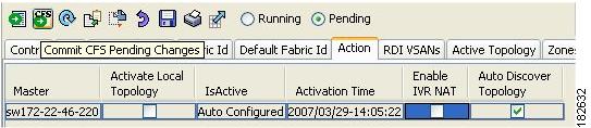
Step 2 ![]() Click the Action tab.
Click the Action tab.
Step 3 ![]() Uncheck the Enable IVR NAT check box (see Figure 2-3).
Uncheck the Enable IVR NAT check box (see Figure 2-3).
Step 4 ![]() Click the Apply Changes icon to distribute this change to all switches in the fabric.
Click the Apply Changes icon to distribute this change to all switches in the fabric.
Manually Configuring and Activating an IVR Topology
You must create the IVR topology on every IVR-enabled switch in the fabric if you have not configured IVR topology in Auto mode. If you choose to manually configure IVR instead of using Auto mode, follow the instructions in this section.
This section includes the following:
•![]() Manual Configuration Guidelines
Manual Configuration Guidelines
•![]() Manually Configuring an IVR Topology
Manually Configuring an IVR Topology
•![]() Activating a Manually Configured IVR Topology
Activating a Manually Configured IVR Topology
Manual Configuration Guidelines
Consider the following guidelines when manually configuring an IVR topology:
•![]() You can configure a maximum of 128 IVR-enabled switches and 128 distinct VSANs in an IVR topology (see the "Database Merge Guidelines" section on page 1-21).
You can configure a maximum of 128 IVR-enabled switches and 128 distinct VSANs in an IVR topology (see the "Database Merge Guidelines" section on page 1-21).
•![]() You will need to specify the IVR topology using the following information:
You will need to specify the IVR topology using the following information:
–![]() The switch WWNs of the IVR-enabled switches.
The switch WWNs of the IVR-enabled switches.
–![]() A minimum of two VSANs to which the IVR-enabled switch belongs.
A minimum of two VSANs to which the IVR-enabled switch belongs.
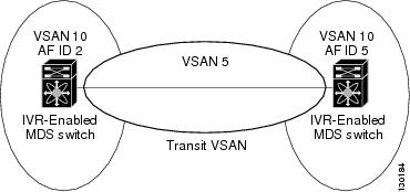
–![]() The AFID, which distinguishes two VSANs that are logically and physically separate, but have the same VSAN number. You can specify up to 64 AFIDs. See Figure 2-4.
The AFID, which distinguishes two VSANs that are logically and physically separate, but have the same VSAN number. You can specify up to 64 AFIDs. See Figure 2-4.
Figure 2-4 Example IVR Topology with Non-Unique VSAN IDs Using AFIDs
•![]() If two VSANs in an IVR topology have the same VSAN ID and different AFIDs, they count as two VSANs for the 128-VSAN limit for IVR.
If two VSANs in an IVR topology have the same VSAN ID and different AFIDs, they count as two VSANs for the 128-VSAN limit for IVR.
•![]() The use of a single AFID does not allow for segmented VSANs in an inter-VSAN routing topology.
The use of a single AFID does not allow for segmented VSANs in an inter-VSAN routing topology.
Manually Configuring an IVR Topology
Note ![]()
You can configure IVR using the IVR tables in the Information pane in Fabric Manager. Use these tables only if you are familiar with all IVR concepts. We recommend you configure IVR using the IVR Wizard. See "Configuring IVR and IVR Zones Using the IVR Zone Wizard" section on page 1-6.
Note ![]() Most tabs in the Information pane for features using CFS are dimmed until you click the CFS tab. The CFS tab shows which switches have CFS enabled and shows the master switch for this feature. Once the CFS tab is clicked, the other tabs in the Information pane are activated.
Most tabs in the Information pane for features using CFS are dimmed until you click the CFS tab. The CFS tab shows which switches have CFS enabled and shows the master switch for this feature. Once the CFS tab is clicked, the other tabs in the Information pane are activated.
To manually configure an IVR topology using Fabric Manager, follow these steps:
Step 1 ![]() Expand All VSANs and then select IVR in the Logical Domains pane.
Expand All VSANs and then select IVR in the Logical Domains pane.
You see the IVR configuration in the Information pane.
Figure 2-5 Local Topology Tab
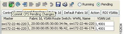
Step 2 ![]() Click the Local Topology tab to display the existing IVR topology.
Click the Local Topology tab to display the existing IVR topology.
Step 3 ![]() Click the Create Row icon to create rows in the IVR topology (see Figure 2-5).
Click the Create Row icon to create rows in the IVR topology (see Figure 2-5).
Step 4 ![]() Select the switch, switch WWN, and a comma-separated list of VSAN IDs for this topology.
Select the switch, switch WWN, and a comma-separated list of VSAN IDs for this topology.
Step 5 ![]() Click Create to create this new row.
Click Create to create this new row.
Step 6 ![]() Click the Apply Changes icon to create the IVR topology.
Click the Apply Changes icon to create the IVR topology.
Repeat this configuration on all IVR-enabled switches or distribute the IVR configuration using CFS.

Tip ![]() Transit VSANs are deduced based on your configuration. The IVR feature does not have an explicit transit-VSAN configuration.
Transit VSANs are deduced based on your configuration. The IVR feature does not have an explicit transit-VSAN configuration.
Activating a Manually Configured IVR Topology
After manually configuring the IVR topology, you must activate it.

To activate a manually configured IVR topology using Fabric Manager, follow these steps:
Step 1 ![]() Expand All VSANs and then select IVR in the Logical Domains pane.
Expand All VSANs and then select IVR in the Logical Domains pane.
You see the IVR configuration in the Information pane.
Figure 2-6 Action Tab
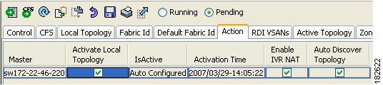
Step 2 ![]() Click the Action tab to display the existing IVR topology.
Click the Action tab to display the existing IVR topology.
Step 3 ![]() Check the Activate Local Topology check box (see Figure 2-6).
Check the Activate Local Topology check box (see Figure 2-6).
Step 4 ![]() Click the Apply Changes icon to activate the IVR topology.
Click the Apply Changes icon to activate the IVR topology.
Working With Existing IVR Topologies
This section includes advanced IVR configurations for existing IVR topologies:
•![]() Clearing a Manually Configured IVR Topology
Clearing a Manually Configured IVR Topology
•![]() Migrating from IVR Auto Topology Mode to Manual Mode
Migrating from IVR Auto Topology Mode to Manual Mode
Clearing a Manually Configured IVR Topology
You can only clear manually created IVR VSAN topology entries.
To clear a manually created IVR topology using Fabric Manager, follow these steps:
Step 1 ![]() Expand All VSANs and then select IVR in the Logical Domains pane.
Expand All VSANs and then select IVR in the Logical Domains pane.
Step 2 ![]() Click the Control tab if it is not already displayed.
Click the Control tab if it is not already displayed.
Step 3 ![]() Highlight the rows you want to delete from the IVR topology.
Highlight the rows you want to delete from the IVR topology.
Step 4 ![]() Click the Delete Row icon to delete these rows from the IVR topology.
Click the Delete Row icon to delete these rows from the IVR topology.
Step 5 ![]() Click the Apply Changes icon to delete the IVR topology.
Click the Apply Changes icon to delete the IVR topology.
Migrating from IVR Auto Topology Mode to Manual Mode
If you want to migrate from Auto mode to Manual mode, copy the active IVR VSAN topology database to the user-configured IVR VSAN topology database before switching modes.
To migrate from Auto mode to Manual mode using Fabric Manager, follow these steps:
Step 1 ![]() Expand All VSANs and then select IVR in the Logical Domains pane.
Expand All VSANs and then select IVR in the Logical Domains pane.
You see the IVR configuration in the Information pane.
Figure 2-7 Action Tab
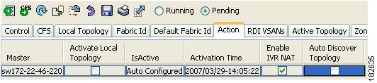
Step 2 ![]() Click the Action tab.
Click the Action tab.
Step 3 ![]() Highlight the switch on which you want to disable auto topology mode.
Highlight the switch on which you want to disable auto topology mode.
Step 4 ![]() Uncheck the Auto Discover Topology check box (see Figure 2-7).
Uncheck the Auto Discover Topology check box (see Figure 2-7).
Step 5 ![]() Click the Apply Changes icon.
Click the Apply Changes icon.
Persistent FC IDs for IVR
This section includes the following information:
•![]() Configuring Persistent FC IDs for IVR
Configuring Persistent FC IDs for IVR
FC ID Features and Benefits
FC ID persistence improves IVR management by providing the following features:
•![]() Allows you to control and assign a specific virtual domain to use in a native VSAN.
Allows you to control and assign a specific virtual domain to use in a native VSAN.
•![]() Allows you to control and assign a specific virtual FC ID for a device.
Allows you to control and assign a specific virtual FC ID for a device.
The benefits of persistent FC IDs for IVR are as follows:
•![]() Host devices always see the same FC ID for targets.
Host devices always see the same FC ID for targets.
•![]() FC IDs help you plan your SAN layout better by assigning virtual domains for IVR to use.
FC IDs help you plan your SAN layout better by assigning virtual domains for IVR to use.
•![]() FC IDs can make SAN monitoring and management easier. When you see the same domain or FC ID consistently assigned, you can readily determine the native VSAN or device to which it refers.
FC IDs can make SAN monitoring and management easier. When you see the same domain or FC ID consistently assigned, you can readily determine the native VSAN or device to which it refers.
FC ID Guidelines
Before configuring persistent FC IDs, consider the following:
•![]() You can configure two types of database entries for persistent IVR FC IDs:
You can configure two types of database entries for persistent IVR FC IDs:
–![]() Virtual domain entries—Contain the virtual domain that should be used to represent a native VSAN in a specific VSAN (current VSAN). Virtual domain entries contain the following information:
Virtual domain entries—Contain the virtual domain that should be used to represent a native VSAN in a specific VSAN (current VSAN). Virtual domain entries contain the following information:
Native AFID
Native VSAN
Current AFID
Current VSAN
Virtual domain to be used for the native AFID and VSAN in current AFID and VSAN
–![]() Virtual FC ID entries—Contain the virtual FC ID that should be used to represent a device in a specific VSAN (current VSAN). Virtual FC ID entries contain the following information:
Virtual FC ID entries—Contain the virtual FC ID that should be used to represent a device in a specific VSAN (current VSAN). Virtual FC ID entries contain the following information:
Port WWN
Current AFID
Current VSAN
Virtual FC ID to be used to represent a device for the given pWWN in the current AFID and VSAN
•![]() If you use persistent FC IDs for IVR, we recommend that you use them for all the devices in the IVR zone set. We do not recommend using persistent FC IDs for some of the IVR devices while using automatic allocation for other devices.
If you use persistent FC IDs for IVR, we recommend that you use them for all the devices in the IVR zone set. We do not recommend using persistent FC IDs for some of the IVR devices while using automatic allocation for other devices.
•![]() IVR NAT must be enabled to use IVR persistent FC IDs.
IVR NAT must be enabled to use IVR persistent FC IDs.
•![]() In an IVR NAT configuration, if one VSAN in the IVR topology is configured with static domain IDs, then the IVR domains that can be exported to that VSAN must also be assigned static domains.
In an IVR NAT configuration, if one VSAN in the IVR topology is configured with static domain IDs, then the IVR domains that can be exported to that VSAN must also be assigned static domains.
Configuring Persistent FC IDs for IVR
To configure persistent FC IDs for IVR using Fabric Manager, follow these steps:
Step 1 ![]() Expand All VSANs and then select IVR in the Logical Domains pane.
Expand All VSANs and then select IVR in the Logical Domains pane.
You see the IVR configuration in the Information pane.
Figure 2-8 FCID Tab
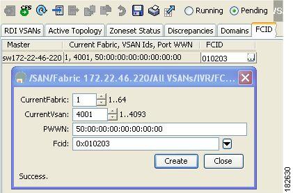
Step 2 ![]() Click the FCID tab.
Click the FCID tab.
Step 3 ![]() Click the Create Row icon to create an FC ID (see Figure 2-8).
Click the Create Row icon to create an FC ID (see Figure 2-8).
Step 4 ![]() Select the switch for which you are configuring the virtual FC ID to be used to represent a device in a specific VSAN (current VSAN).
Select the switch for which you are configuring the virtual FC ID to be used to represent a device in a specific VSAN (current VSAN).
Step 5 ![]() Enter the current fabric in the Current Fabric ID field for the fcdomain database.
Enter the current fabric in the Current Fabric ID field for the fcdomain database.
Step 6 ![]() Enter the current VSAN in the Current VSAN ID field for the fcdomain database.
Enter the current VSAN in the Current VSAN ID field for the fcdomain database.
Step 7 ![]() Enter the pWWN.
Enter the pWWN.
Step 8 ![]() Click the drop-down menu to select the FC ID to map to the pWWN you selected.
Click the drop-down menu to select the FC ID to map to the pWWN you selected.
Step 9 ![]() Click Create to create this new row.
Click Create to create this new row.
Advanced IVR Zones and IVR Zone Sets
This section describes advanced configuration information for IVR zones and IVR zone sets. For basic information on configuring IVR zones and zone sets, see the "IVR Zones and IVR Zone Sets" section on page 1-12.
As part of the IVR configuration, you need to configure one or more IVR zone to enable cross-VSAN communication. To achieve this, you must specify each IVR zone as a set of (pWWN, VSAN) entries. Different IVR zone sets can contain the same IVR zone, because IVR zones can be members of one or more IVR zone sets.
Note ![]() The same IVR zone set must be activated on all of the IVR-enabled switches.
The same IVR zone set must be activated on all of the IVR-enabled switches.
This section includes the following topics:
•![]() IVR Zone Configuration Guidelines
IVR Zone Configuration Guidelines
•![]() Configuring QoS for IVR Zones
Configuring QoS for IVR Zones
•![]() Renaming IVR Zones and IVR Zone Sets
Renaming IVR Zones and IVR Zone Sets
•![]() Configuring IVR Using Read-Only Zoning
Configuring IVR Using Read-Only Zoning
IVR Zone Configuration Guidelines
When interop mode is enabled, consider the following IVR configuration guidelines:
•![]() When a member's native VSAN is in interop mode (for example, when the interop mode is 2, 3, or 4), then ReadOnly, the QoS attribute, and LUN zoning are not permitted.
When a member's native VSAN is in interop mode (for example, when the interop mode is 2, 3, or 4), then ReadOnly, the QoS attribute, and LUN zoning are not permitted.
•![]() When a member's VSAN is already in interop mode and an attempt is made to configure ReadOnly, the QoS attribute, or LUN zoning, a warning message is displayed to indicate that the configuration is not permitted.
When a member's VSAN is already in interop mode and an attempt is made to configure ReadOnly, the QoS attribute, or LUN zoning, a warning message is displayed to indicate that the configuration is not permitted.
•![]() When you configure ReadOnly, the QoS attribute, or LUN zoning first, and then change the member's VSAN interop mode, a warning message is displayed to indicate the configuration is not permitted. You are then prompted to change the configuration.
When you configure ReadOnly, the QoS attribute, or LUN zoning first, and then change the member's VSAN interop mode, a warning message is displayed to indicate the configuration is not permitted. You are then prompted to change the configuration.
Configuring QoS for IVR Zones
To configure QoS for an IVR zone using Fabric Manager, follow these steps:
Note ![]() The default QoS attribute setting is low.
The default QoS attribute setting is low.
Step 1 ![]() Choose Zone > Edit Local Full Zone Database.
Choose Zone > Edit Local Full Zone Database.
You see the Edit IVR Local Full Zone Database dialog box for the VSAN you selected.
Step 2 ![]() Select Zones or a zone set.
Select Zones or a zone set.
Step 3 ![]() Check the QoS check box and set the QoS priority.
Check the QoS check box and set the QoS priority.
Step 4 ![]() Click Activate to make the changes.
Click Activate to make the changes.
Note ![]() If other QoS attributes are configured, the highest setting takes priority.
If other QoS attributes are configured, the highest setting takes priority.
Renaming IVR Zones and IVR Zone Sets
To rename an IVR zone or IVR zone set, using Fabric Manager, follow the steps below:
Step 1 ![]() Choose Zone > Edit Local Full Zone Database.
Choose Zone > Edit Local Full Zone Database.
You see the Edit IVR Local Full Zone Database dialog box for the VSAN you selected.
Step 2 ![]() Click a zone or zone set in the left pane.
Click a zone or zone set in the left pane.
Step 3 ![]() Choose Edit > Rename.
Choose Edit > Rename.
An edit box appears around the zone or zone set name.
Step 4 ![]() Enter a new name.
Enter a new name.
Step 5 ![]() Click Activate or Commit Changes.
Click Activate or Commit Changes.
Configuring IVR Using Read-Only Zoning
Read-only zoning (with or without LUNs) can be used between members of active IVR zones. To configure this service, you must create and activate read-only zones between the desired IVR zone members in all relevant edge VSANs using the zoning interface.
Note ![]() Read-only zoning cannot be configured in an IVR zone set setup.
Read-only zoning cannot be configured in an IVR zone set setup.
 Feedback