Feedback
Table Of Contents
Configuring Generation 2 Switches and Modules
About Generation 2 Modules and Switches
BB_Credit Buffers for Switching Modules
48-port 4-Gbps Fibre Channel Module BB_Credit Buffers
24-port 4-Gbps Fibre Channel Module BB_Credit Buffers
18-Port Fibre Channel/4-Port GigabitEthernet Multiservice Module BB_Credit Buffers
12-Port 4-Gbps Switching Module BB_Credit Buffers
4-Port 10-Gbps Switching Module BB_Credit Buffers
BB_Credit Buffers for Fabric Switches
Cisco MDS 9134 Fabric Switch BB_Credit Buffers
Cisco MDS 9124 Fabric Switch BB_Credit Buffers
Cisco MDS 9222i Multiservice Modular Switch BB_Credit Buffers
About Combining Generation 1 and Generation 2 Switching Modules
Configuring Generation 2 Module Interface Shared Resources
Displaying Interface Capabilities
Configuration Guidelines for 48-Port and 24-Port 4-Gbps Fibre Channel Switching Modules
Migrating from Shared Mode to Dedicated Mode
Migrating from Dedicated Mode to Shared Mode
Configuration Guidelines for 12-Port 4-Gbps Switching Module Interfaces
Configuration Guidelines for 4-Port 10-Gbps Switching Module Interfaces
Configuring Oversubscription Ratio Restrictions
Disabling Restrictions on Oversubscription Ratios
Oversubscription Ratio Restrictions Example
Enabling Restrictions on Oversubscription Ratios
Configuring Bandwidth Fairness
Taking Interfaces Out of Service
Releasing Shared Resources in a Port Group
Enabling the Buffer-to-Buffer State Change Number
Disabling ACL Adjacency Sharing for System Image Downgrade
Displaying SFP Diagnostic Information
Configuring a 24-port 4-Gbps Fibre Channel Switching Module Example
Configuring a 48-port 4-Gbps Fibre Channel Switching Module Example
Configuring Generation 2 Switches and Modules
The Cisco MDS 9500 Series switches and Cisco MDS 9216A and Cisco MDS 9216i switches support a set of modules called Generation 2 modules. This chapter describes how to configure these modules, as well as Generation 2 Multilayer Fabric Switches.
This chapter includes the following sections:
•
About Generation 2 Modules and Switches
•
•
•
•
About Generation 2 Modules and Switches
Table 14-1 identifies the modules supported by the Cisco MDS 9500 Series switches and Cisco MDS 9216A and Cisco MDS 9216i switches, as well as the Fabric switches:
Note
For detailed information about the installation and specifications for these modules and switches, refer to the hardware installation guide for your switch.
This section includes the following topics:
Port Groups
Each module or switch can have one or more ports in port groups that share common resources (such as bandwidth and buffer credits). Table 14-2 shows the port groups for the Generation 2 Fibre Channel switches and modules.
Table 14-2 Bandwidth and Port Groups for Generation 2 FC Modules and Fabric Switches
DS-X9148
Cisco 48-port 4-Gbps Fibre Channel module
48-port 4-Gbps Fibre Channel switching module1
12
12.8
4-Gbps
DS-X9124
Cisco 24-port 4-Gbps Fibre Channel module
24-port 4-Gbps Fibre Channel switching module
6
12.8
4
DS-X9304-18K9
Cisco 18-port Fibre Channel /4-port GigabitEthernet Multiservice (MSM-18/4) module
18-port 4-Gbps Fibre Channel switching module with 4 GigabitEthernet ports
6
12.8
4-Gbps
DS-X9112
Cisco 12-port 4-Gbps Fibre Channel module
12-port 4-Gbps Fibre Channel switching module
3
12.8
4-Gbps
DS-X9704
Cisco 4-port 10-Gbps Fibre Channel module
4-port 10-Gbps Fibre Channel switching module
1
10
10-Gbps
DS-C9134-K9
Cisco MDS 9134 Fabric switch
32-port 4-Gbps Fabric switch
4
16
4-Gbps
2-port 10-Gbps Fabric switch
1
10
10-Gbps
DS-C9124K9
Cisco MDS 9124 Fabric switch
24-port 4-Gbps
4
16
4-Gbps
DS-C9222i-K9
Cisco MDS 9222i Multiservice Modular switch
18-port 4-Gbps
6
12.8
4-Gbps
1 By default, all ports in a 48-port 4-Gbps switching module operate in shared mode with administrative operating speed set to auto. All ports in a 48-port 4-Gbps switching module can operate in dedicated mode with a 1-Gbps operating speed. However, if you configure one or more ports to operate in 2-Gbps or 4-Gbps dedicated mode, some of the other ports in the module would have to operate in shared mode.
Note
Port Rate Modes
The Port rate mode configuration is used to determine the bandwidth allocation for ports in a port group. Two port rate modes are supported: Dedicated Mode and Shared Mode. In Generation 1 modules, port rate mode is not configurable by users; rather, it is determined implicitly based on the port mode and linecard type. In Generation 2 modules, port rate mode is user-configured.
Table 14-3 Port Rate Mode Support on Generation 2 Modules and Switches
DS-X9148
Cisco 48-port 4-Gbps Fibre Channel module
48-port 4-Gbps Fibre Channel switching module1
Yes
Yes
DS-X9124
Cisco 24-port 4-Gbps Fibre Channel module
24-port 4-Gbps Fibre Channel switching module
Yes
Yes
DS-X9304-18K9
Cisco 18-port Fibre Channel /4-port GigabitEthernet Multiservice (MSM-18/4) module
18-port 4-Gbps Fibre Channel switching module with 4 GigabitEthernet ports
Yes
Yes
DS-X9112
12-port 4-Gbps Fibre Channel module
12-port 4-Gbps Fibre Channel switching module
Yes
No
DS-X9704
4-port 10-Gbps Fibre Channel module
4-port 10-Gbps Fibre Channel switching module
Yes
No
DS-C9134-K9
Cisco MDS 9134 Fabric switch
32-port 4-Gbps Fabric switch
Yes
Yes
2-port 10-Gbps Fabric switch
Yes
No
DS-C9124
Cisco MDS 9124 Fabric switch
24-port 4-Gbps Fabric switch2
Yes
No
DS-C9222i-K9
Cisco MDS 9222i Multiservice Modular switch
18-port 4-Gbps Fibre Channel switch with 4 GigabitEthernet IP storage services ports, and a modular expansion slot to host Cisco MDS 9000 Family Switching and Services Modules
Yes
Yes
1 By default, all ports in a 48-port 4-Gbps switching module operate in shared mode with administrative operating speed set to auto. All ports in a 48-port 4-Gbps switching module can operate in dedicated mode with a 1-Gbps operating speed. However, if you configure one or more ports to operate in 2-Gbps or 4-Gbps dedicated mode, some of the other ports in the module would have to operate in shared mode.
2 By default, all ports in a 24-port 4-Gbps switching module operate in shared mode with administrative operating speed set to auto. All ports in a 24-port 4-Gbps switching module can operate in dedicated mode with a 2-Gbps operating speed. However, if you configure one or more ports to operate in 4-Gbps dedicated mode, some of the other ports in the module would have to operate in shared mode
Note
Dedicated Mode
When port rate mode is configured as dedicated, a port is allocated required fabric bandwidth and related resources to sustain line rate traffic at the maximum operating speed configured for the port. In this mode, ports do not use local buffering and all receive buffers are allocated from a global buffer pool (see the "Buffer Pools" section).
Table 14-4 show the amount of bandwidth reserved for a configured port speed on 4-Gbps switching modules.
Table 14-4 Bandwidth Reserved for the Port Speeds on 4-Gbps Switching Modules
Auto
4 Gbps
4-Gbps
Auto with 2-Gbps maximum
2 Gbps
2-Gbps
1-Gbps
1 Gbps
Note
Shared Mode
When port rate mode is configured as shared, multiple ports within a port group share data paths to the switch fabric so that fabric bandwidth and related resources are shared. Often, the available bandwidth to the switch fabric may be less than the negotiated operating speed of a port. Ports in this mode use local buffering for the BB_credit buffers.
All ports in switching modules where bandwidth is shared support 1-Gbps, 2-Gbps, or 4-Gbps traffic. However, it is possible to configure one or more ports in a port group to operate in dedicated mode with 1-Gbps, 2-Gbps or 4-Gbps operating speed.
Dynamic Bandwidth Management
On port switching modules where bandwidth is shared, the bandwidth available to each port within a port group can be configured based on the port rate mode and speed configurations. Within a port group, some ports can be configured in dedicated mode while others operate in shared mode.
Ports configured in dedicated mode are allocated the required bandwidth to sustain a line rate of traffic at the maximum configured operating speed, and ports configured in shared mode share the available remaining bandwidth within the port group. Fair allocation of bandwidth among a group of ports is determined, in part, by the rate mode and speed configurations. For example, if the set ports in a module are configured with the same rate mode and speed (such as 4 Gbps of shared bandwidth), then all the ports should have fair allocation of bandwidth and eventually, similar throughput. When you enable bandwidth fairness, you should notice a reduction in any disparity that may otherwise exist in similar configurations.
Bandwidth allocation among the shared mode ports is based on the operational speed of the ports. For example, if four ports operating at speeds 1 Gbps, 1 Gbps, 2 Gbps, and 4 Gbps share bandwidth of 8 Gbps, the ratio of allocation would be 1:1:2:4.
Note
Tip
Note
Out-of-Service Interfaces
On supported modules and fabric switches, you might need to allocate all the shared resources for one or more interfaces to another interface in the port group or module. You can take interfaces out of service to release shared resources that are needed for dedicated bandwidth. When an interface is taken out of service, all shared resources are released and made available to the other interface in the port group or module. These shared resources include bandwidth, rate mode, BB_credits, and extended BB_credits. All shared resource configurations are returned to their default values when the interface is brought back into service. Corresponding resources must be made available in order for the port to be successfully returned to service.
Caution
Buffer Credit Allocation
This sections describe how buffer credits are allocated to switches and modules, and includes the following topics:
•
•
Buffer Pools
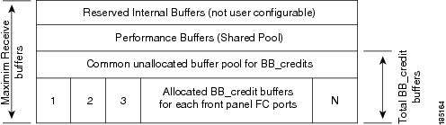
In the architecture of Generation 2 modules, receive buffers shared by a set of ports are called buffer groups. The receive buffer groups are organized into global and local buffer pools.
The receive buffers allocated from the global buffer pool to be shared by a port group are called a global buffer pool. Global receive buffer pools include the following buffer groups:
•
•
•
•
Figure 14-1 shows the allocation of BB_credit buffers on linecards (24-port and 48-port line cards).
Note
Figure 14-1 Receive Buffers for Fibre Channel Ports in a Global Buffer Pool
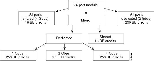
Figure 14-2 shows the default BB_credit buffer allocation model for 24-port 4-Gbps switching modules. The minimum BB_credits required to bring up a port is two buffers.
Figure 14-2 BB_Credit Buffer Allocation in 24-port 4-Gbps Switching Modules
Note
BB_Credit Buffers for Switching Modules
This section describes how buffer credits are allocated to Cisco MDS 9000 switching modules, and includes the following topics:
•
•
•
•
•
48-port 4-Gbps Fibre Channel Module BB_Credit Buffers
Table 14-5 lists the BB_credit buffer allocation for 48-port 4-Gbps Fibre Channel switching modules.
Table 14-5 48-Port 4-Gbps Switching Module BB_Credit Buffer Allocation Defaults
User configurable BB_credit buffers
6000
125
16
16
16
1 ISL = E port or TE port.
The following considerations apply to BB_credit buffers on 48-port 4-Gbps Fibre Channel switching modules:
•
•
•
Each port group on the 48-port 4-Gbps Fibre Channel switching module consists of 12 ports. The ports in shared rate mode have bandwidth oversubscription of 4:1 by default. However, some configurations of the shared ports in a port group can have maximum bandwidth oversubscription of 5:1 (considering that each port group has 12.8-Gbps bandwidth).
The following example configurations are supported by the 48-port 4-Gbps Fibre Channel switching modules:
•
•
11 ports with shared rate mode and 4-Gbps speed (5:1 oversubscription)•
11 ports with shared rate mode and 2-Gbps speed (2.5:1 oversubscription)•
10 ports with shared rate mode and 4-Gbps speed (5:1 oversubscription)•
10 ports with shared rate mode and 2-Gbps speed (2.5:1 oversubscription)•
•
four ports with shared rate mode and 1-Gbps speed plus
five ports put out-of-service (see Figure 14-3)Figure 14-3 Example Speed and Rate Configuration on a 48-Port 4-Gbps Switching Module
•
four ports with shared rate mode and 1-Gbps speed plus
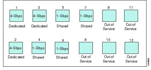
two ports put out-of-service (see Figure 14-4)
Note
Figure 14-4 Example Speed and Rate Configuration on a 48-Port 4-Gbps Switching Module
24-port 4-Gbps Fibre Channel Module BB_Credit Buffers
Table 14-7 lists the BB_credit buffer allocation for 24-port 4-Gbps Fibre Channel switching modules.
Table 14-6 24 Port 4-Gbps Switching Module BB_Credit Buffer Allocation Defaults
User configurable BB_credit buffers
6000
250
16
16
16
1 ISL = E port or TE port.
The following considerations apply to BB_credit buffers on 24-port 4-Gbps Fibre Channel switching modules:
•
•
•
Each port group on the 24-port 4-Gbps Fibre Channel switching module consists of six ports. The ports in shared rate mode have bandwidth oversubscription of 2:1 by default. However, some configurations of the shared ports in a port group can have maximum bandwidth oversubscription of 4:1 (considering that each port group has 12.8-Gbps bandwidth). The following example configurations are supported by the 24-port 4-Gbps Fibre Channel switching modules:
•
•
four ports with shared rate mode and 4-Gbps speed (with 4:1 oversubscription)•
three ports with dedicated rate mode and 2-Gbps speed plus
two ports with shared rate mode and 4-Gbps speed (4:1 oversubscription)•
•
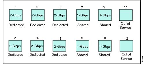
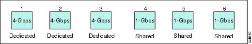
three ports with shared rate mode and 1-Gbps speed (see Figure 14-5)
Note
Figure 14-5 Example Speed and Rate Configuration on a 24-Port 4-Gbps Switching Module
18-Port Fibre Channel/4-Port GigabitEthernet Multiservice Module BB_Credit Buffers
Table 14-7 lists the BB_credit buffer allocation for 18-port 4-Gbps multiservice modules.
Table 14-7 18-Port 4-Gbps Multiservice Module BB_Credit Buffer Allocation Defaults
User configurable BB_credit buffers
4509
250
16
16
16
1 ISL = E port or TE port.
The following considerations apply to BB_credit buffers on18-port 4-Gbps Fibre Channel switching modules:
•
•
•
12-Port 4-Gbps Switching Module BB_Credit Buffers
Table 14-8 lists the BB_credit buffer allocation for 12-port 4-Gbps switching modules.
Table 14-8 12-Port 4-Gbps Switching Module BB_Credit Buffer Allocation Defaults
User configurable BB_credit buffers
5488
250
16
Performance buffers
512 (shared)
145
12
1 ISL = E port or TE port.
The following considerations apply to BB_credit buffers on 12-port 4-Gbps switching modules:
•
•
•
•
Note
Note
4-Port 10-Gbps Switching Module BB_Credit Buffers
Table 14-9 lists the BB_credit buffer allocation for 4-port 10-Gbps switching modules.
Table 14-9 4-port 10-Gbps Switching Module BB_Credit Buffer Allocation Defaults
User configurable BB_credit buffers
5488
250
16
Performance buffers
512 (shared)
145
12
1 ISL = E port or TE port.
2 Ports on the 4-port 10-Gbps cannot operate in FL port mode.
Note
The following considerations apply to BB_credit buffers on 4-port 10-Gbps switching modules:
•
•
•
•
Note
BB_Credit Buffers for Fabric Switches
This section describes how buffer credits are allocated to Cisco MDS 9000 Fabric switches, and includes the following topics:
•
•
•
Cisco MDS 9134 Fabric Switch BB_Credit Buffers
Table 14-10 lists the BB_credit buffer allocation for 32-port 4-Gbps Fibre Channel switches.
Table 14-10 32-Port 4-Gbps Switching Module BB_Credit Buffer Allocation Defaults
User configurable BB_credit buffers
64
64
64
1 ISL = E port or TE port.
The following considerations apply to BB_credit buffers on 32-port 4-Gbps switches:
•
•
Cisco MDS 9124 Fabric Switch BB_Credit Buffers
Table 14-11 lists the BB_credit buffer allocation for 24-port 4-Gbps Fibre Channel switches.
Table 14-11 24-Port 4-Gbps Switching Module BB_Credit Buffer Allocation Defaults
User configurable BB_credit buffers
64
16
16
1 ISL = E port or TE port.
Cisco MDS 9222i Multiservice Modular Switch BB_Credit Buffers
Table 14-12 lists the BB_credit buffer allocation for 18-port 4-Gbps Multiservice Modular switches.
Table 14-12 18-Port 4-Gbps Switching Module BB_Credit Buffer Allocation Defaults
User configurable BB_credit buffers
4509
250
16
1 ISL = E port or TE port.
Extended BB_Credits
Note
To facilitate BB_credits for long haul links, the extended BB_credits feature allows the user to configure the receive buffers above the maximum value on all Generation 2 switching modules (see the "Buffer Credit Allocation" section). When necessary, you can reduce the buffers on one port and assign them to another port, exceeding the default maximum. The minimum extended BB_credits per port is 256 and the maximum is 4095.
In general, the user can configure any port in a port group to dedicated mode. To do this, you must first release the buffers from the other ports before configuring larger extended BB_credits for a port.
Note
All ports on the Generation 2 switching modules support extended BB_credits. There are no limitations for how many extended BB_credits you can assign to a port (except for the maximum and minimum limits). If necessary, you can take interfaces out of service to make more extended BB_credits available to other ports.
About Combining Generation 1 and Generation 2 Switching Modules
You can combine Generation 1 and Generation 2 switching modules, with either Supervisor-1 modules or Supervisor-2 modules. However, combining switching modules and supervisor modules has the following port index limitations:
•
•
•
Port Indexes
Cisco MDS 9000 switches allocate index identifiers for the ports on the modules. These port indexes cannot be configured. You can combine Generation 1 and Generation 2 switching modules, with either Supervisor-1 modules or Supervisor-2 modules. However, combining switching modules and supervisor modules has the following port index limitations:
•
•
•
Note
You can use the show port index-allocation command to display the allocation of port indexes on the switch.
switch# show port index-allocationModule index distribution:------------------------------------------------------+Slot | Allowed | Alloted indices info || range | Total | Index values |-----|---------|-------|------------------------------|1 | 0- 255| 16 | 32-47 |2 | 0- 255| 12 | 0-11 |3 | 0- 255| - | (None) |4 | 0- 255| - | (None) |7 | 0- 255| - | (None) |8 | 0- 255| - | (None) |9 | 0- 255| - | (None) |SUP | ----- | 3 | 253-255 |Generation 1 switching modules have specific numbering requirements. If these requirements are not met, the module does not power up. The port index numbering requirements include the following:
•
•
Note
The allowed mix of Generation 1 and Generation 2 switching modules in a chassis is determined at run-time, either when booting up the switch or when installing the modules. In some cases, the sequence in which switching modules are inserted into the chassis determines if one or more modules is powered up. When a module does not power up because of a resource limitation, you can display the reason by using the show module command.
switch# show moduleMod Ports Module-Type Model Status--- ----- -------------------------------- ------------------ ------------1 16 1/2 Gbps FC Module DS-X9016 ok2 12 1/2/4 Gbps FC Module powered-dn5 0 Supervisor/Fabric-2 DS-X9530-SF2-K9 active *Mod Power-Status Power Down Reason--- ------------ ---------------------------2 powered-dn Insufficient resources (dest Index)* this terminal sessionMod MAC-Address(es) Serial-Num--- -------------------------------------- ----------1 00-0b-be-f7-4c-24 to 00-0b-be-f7-4c-28 JAB070307232 00-05-30-01-a8-b2 to 00-05-30-01-a8-b6 JAB090401AA5 00-05-30-01-aa-7e to 00-05-30-01-aa-82 JAB091100TF* this terminal sessionThe running configuration is updated when modules are installed. If you save the running configuration to the startup configuration (using the copy running-config startup-config command), during reboot the switch powers up the same set of modules as before the reboot regardless of the sequence in which the modules initialize. You can use the show port index-allocation startup command to display the index allocation the switch uses at startup.
switch# show port index-allocation startupStartup module index distribution:------------------------------------------------------+Slot | Allowed | Alloted indices info || range | Total | Index values |-----|---------|-------|------------------------------|1 | ----- | 34 | 0-31,80-81 |2 | ----- | 32 | 32-63 |3 | ----- | 16 | 64-79 |(Slot 1 shares 80-81)4 | ----- | 48 | 96-127,224-239 |SUP | 253-255 | 3 | 253-255 |
Note
If a module fails to power up, you can use the show module slot recovery-steps command to display the reason. For information on recovering a module powered-down because port indexes are not available, refer to the Cisco MDS 9000 Family Troubleshooting Guide, Release 3.x.
Tip
PortChannels
PortChannels have the following restrictions:
•
•
•
Note
When configuring PortChannels on switches with both Generation 1 and Generation 2 switching modules, configure the PortChannel and Generation 2 switching modules interfaces to auto with a maximum of 2 Gbps or configure the Generation 1 switching modules followed by the Generation 2 switching modules.
Note
Note
Table 14-14 describes the results of adding a member to a PortChannel for various configurations.
Table 14-14 PortChannel Configuration and Addition Results
No members
Any
Any
Generation 1 or Generation 2
Force
Pass
Auto
Auto
Generation 1 or Generation 2
Normal or force
Pass
Auto max 2000
Auto
Generation 1
Normal or force
Pass
Auto max 2000
Auto
Generation 2
Normal
Fail
Force
Pass
Auto
Auto max 2000
Generation 2
Normal
Fail
Force
Pass or fail1
Generation 1 interfaces
Auto
Auto
Generation 2
Normal
Fail
Force
Pass
Auto max 2000
Auto
Generation 1
Normal or force
Pass
Auto max 2000
Auto
Generation 2
Normal
Fail
Force
Pass or fail1
Generation 2 interfaces
Auto
Auto
Generation 1
Normal or force
Fail
Auto max 2000
Auto
Generation 1
Normal or force
Pass
Auto max 2000
Auto
Generation 2
Normal
Fail
Force
Pass
Auto
Auto max 2000
Generation 2
Normal
Fail
Force
Pass
1 Is resources not available.
Use the show port-channel compatibility parameters command to obtain information about PortChannel addition errors.
Configuring Generation 2 Module Interface Shared Resources
This section describes how to configure Generation 2 module interface shared resources and contains the following sections:
•
•
•
•
•
•
•
•
•
Displaying Interface Capabilities
Before configuring a Generation 2 interface, you can use the show interface capabilities command to display detailed information about the capabilities of the interface.
switch# show interface fc 9/1 capabilitiesMin Speed is 1 GbpsMax Speed is 4 GbpsFC-PH Version (high, low) (0,6)Receive data field size (max/min) (2112/256) bytesTransmit data field size (max/min) (2112/128) bytesClasses of Service supported are Class 2, Class 3, Class FClass 2 sequential delivery supportedClass 3 sequential delivery supportedHold time (max/min) (100/1) micro secBB state change notification supportedMaximum BB state change notifications 14Rate Mode change supportedRate Mode Capabilities Shared DedicatedReceive BB Credit modification supported yes yesFX mode Receive BB Credit (min/max/default) (1/16/16) (1/250/16)ISL mode Receive BB Credit (min/max/default) -- (2/250/250)Performace buffer modification supported no noOut of Service capable yesBeacon mode configurable yesConfiguration Guidelines for 48-Port and 24-Port 4-Gbps Fibre Channel Switching Modules
The 48-port and 24-port 4-Gbps Fibre Channel switching modules support the following features:
•
•
•
•
Migrating from Shared Mode to Dedicated Mode
To configure 48-port and 24-port 4-Gbps Fibre Channel switching modules when starting with the default configuration or when migrating from shared rate mode to dedicated rate mode, follow these guidelines:
1.
See the "Taking Interfaces Out of Service" section.
2.
See the "Configuring Port Speed" section.
3.
See the "Configuring Rate Mode" section.
4.
See the "About Interface Modes" section on page 12-3.
Note
5.
See the "Extended BB_Credits" section.
Migrating from Dedicated Mode to Shared Mode
To configure 48-port and 24-port 4-Gbps Fibre Channel switching modules migrating from dedicated rate mode to shared rate mode, follow these guidelines:
1.
See the "Taking Interfaces Out of Service" section.
2.
See the "BB_Credit Buffers for Switching Modules" section, "BB_Credit Buffers for Fabric Switches" section, and the "Extended BB_Credits" section.
3.
See the "About Interface Modes" section on page 12-3.
Note
4.
See the "Configuring Rate Mode" section.
5.
See the "Configuring Port Speed" section.
Configuration Guidelines for 12-Port 4-Gbps Switching Module Interfaces
The 12-port 4-Gbps switching modules support the following features:
•
•
•
•
•
To configure 4-port 10-Gbps switching modules when starting with the default configuration, follow these guidelines:
1.
See the "Configuring Port Speed" section.
2.
See the "About Interface Modes" section on page 12-3.
3.
See the "BB_Credit Buffers for Switching Modules" section, "BB_Credit Buffers for Fabric Switches" section, and the "Extended BB_Credits" section.
Note
Configuration Guidelines for 4-Port 10-Gbps Switching Module Interfaces
The 4-port 10-Gbps switching modules support the following features:
•
•
•
•
•
Use the following guidelines to configure 4-port 10-Gbps switching modules when starting with the default configuration:
1.
See the "About Interface Modes" section on page 12-3.
2.
See the "BB_Credit Buffers for Switching Modules" section, "BB_Credit Buffers for Fabric Switches" section, and the "Extended BB_Credits" section.
Configuring Port Speed
The port speed on an interface, combined with the rate mode, determines the amount of shared resources available to the ports in the port group on a 48-port or 24-port 4-Gbps Fibre Channel switching module. Especially in the case of dedicated rate mode, the port group resources are reserved even though the bandwidth is not used. For example, if an interface is configured for autosensing (auto) and dedicated rate mode, then 4 Gbps of bandwidth is reserved even though the maximum operating speed is 2 Gbps. For the same interface, if autosensing with a maximum speed of 2 Gbps (auto max 2000) is configured, then only 2 Gbps of bandwidth is reserved and the unused 2 Gbps is shared with the other interface in the port group.
Caution
Note
To configure the port speed on an interface on a 4-Gbps switching module, follow these steps:
Use the show interface command to verify the port speed configuration for an interface on a 24-port or 48-port 4-Gbps Fibre Channel switching module.
switch# show interface fc 9/1fc9/1 is upHardware is Fibre Channel, SFP is short wave laser w/o OFC (SN)Port WWN is 22:01:00:05:30:01:9f:02Admin port mode is Fsnmp traps are enabledPort mode is F, FCID is 0xeb0002Port vsan is 1Speed is 2 GbpsRate mode is sharedTransmit B2B Credit is 64Receive B2B Credit is 16Receive data field Size is 2112Beacon is turned off5 minutes input rate 0 bits/sec, 0 bytes/sec, 0 frames/sec5 minutes output rate 0 bits/sec, 0 bytes/sec, 0 frames/sec226 frames input, 18276 bytes0 discards, 0 errors0 CRC, 0 unknown class0 too long, 0 too short326 frames output, 21364 bytes0 discards, 0 errors0 input OLS, 0 LRR, 1 NOS, 0 loop inits3 output OLS, 2 LRR, 0 NOS, 0 loop inits16 receive B2B credit remaining64 transmit B2B credit remainingConfiguring Rate Mode
To configure the rate mode (dedicated or shared) on an interface on a 48-port or 24-port 4-Gbps Fibre Channel switching module, follow these steps:
To configure the rate mode (dedicated or shared) on an interface on a 48-port or 24-port 4-Gbps Fibre Channel switching module, follow these steps:
Caution
Use show port-resources module command to verify the rate mode configuration for interfaces on a 48-port or 24-port 4-Gbps Fibre Channel switching module.
switch# show port-resources module 9Module 9Available dedicated buffers are 5400Port-Group 1Total bandwidth is 12.8 GbpsTotal shared bandwidth is 12.8 GbpsAllocated dedicated bandwidth is 0.0 Gbps--------------------------------------------------------------------Interfaces in the Port-Group B2B Credit Bandwidth Rate ModeBuffers (Gbps)--------------------------------------------------------------------fc9/1 16 4.0 sharedfc9/2 16 4.0 sharedfc9/3 16 4.0 sharedfc9/4 16 4.0 sharedfc9/5 16 4.0 sharedfc9/6 16 4.0 sharedPort-Group 2Total bandwidth is 12.8 GbpsTotal shared bandwidth is 12.8 GbpsAllocated dedicated bandwidth is 0.0 Gbps--------------------------------------------------------------------Interfaces in the Port-Group B2B Credit Bandwidth Rate ModeBuffers (Gbps)--------------------------------------------------------------------fc9/7 16 4.0 sharedfc9/8 16 4.0 sharedfc9/9 16 4.0 sharedfc9/10 16 4.0 sharedfc9/11 16 4.0 sharedfc9/12 16 4.0 sharedPort-Group 3Total bandwidth is 12.8 GbpsTotal shared bandwidth is 12.8 GbpsAllocated dedicated bandwidth is 0.0 Gbps--------------------------------------------------------------------Interfaces in the Port-Group B2B Credit Bandwidth Rate ModeBuffers (Gbps)--------------------------------------------------------------------fc9/13 16 4.0 sharedfc9/14 16 4.0 sharedfc9/15 16 4.0 sharedfc9/16 16 4.0 sharedfc9/17 16 4.0 sharedfc9/18 16 4.0 sharedPort-Group 4Total bandwidth is 12.8 GbpsTotal shared bandwidth is 12.8 GbpsAllocated dedicated bandwidth is 0.0 Gbps--------------------------------------------------------------------Interfaces in the Port-Group B2B Credit Bandwidth Rate ModeBuffers (Gbps)--------------------------------------------------------------------fc9/19 16 4.0 sharedfc9/20 16 4.0 sharedfc9/21 16 4.0 sharedfc9/22 16 4.0 sharedfc9/23 16 4.0 sharedfc9/24 16 4.0 sharedConfiguring Oversubscription Ratio Restrictions
The 48-port and 24-port 4-Gbps Fibre Channel switching modules support oversubscription on switches with shared rate mode configurations. Table 14-15 describes the bandwidth allocation for oversubscribed interfaces configured in shared mode.
By default, all 48-port and 24-port 4-Gbps Fibre Channel switching modules have restrictions on oversubscription ratios enabled.
As of Cisco SAN-OS Release 3.1(1) and later, you can disable restrictions on oversubscription ratios. All ports in 48-port and 24-port modules can be configured to operate at 4 Gbps in shared mode-even if other ports in the port group are configured in dedicated mode-regardless of available bandwidth. However, when oversubscription ratio restrictions are enabled you may not have all shared ports operating at 4 Gbps. For example, oversubscription ratios are enabled, and you have configured three 4 Gbps dedicated ports in one port group, no other ports in the same port group can be configured to operate at 4 Gbps.
switch# show port-resources module 8Module 8Available dedicated buffers are 5478Port-Group 1Total bandwidth is 12.8 GbpsTotal shared bandwidth is 0.8 GbpsAllocated dedicated bandwidth is 12.0 Gbps--------------------------------------------------------------------Interfaces in the Port-Group B2B Credit Bandwidth Rate ModeBuffers (Gbps)--------------------------------------------------------------------fc8/1 16 4.0 dedicatedfc8/2 16 4.0 dedicatedfc8/3 16 4.0 dedicatedfc8/4 (out-of-service)fc8/5 (out-of-service)fc8/6 (out-of-service)For dedicated ports, oversubscription ratio restrictions do not apply to the shared pool in port groups. So if oversubscription ratio restrictions are disabled, and you've configured three 4 Gbps dedicated ports in one port group, then you can configure all other ports in the same port group to operate at a shared rate of 4 Gbps. In the following example, a 24-port module has a group of 6 ports-3 dedicated ports are operating at 4 Gbps, and 3 shared ports operating at 4 Gbps:
switch# show port-resources module 8Module 8Available dedicated buffers are 5382Port-Group 1Total bandwidth is 12.8 GbpsTotal shared bandwidth is 0.8 GbpsAllocated dedicated bandwidth is 12.0 Gbps--------------------------------------------------------------------Interfaces in the Port-Group B2B Credit Bandwidth Rate ModeBuffers (Gbps)--------------------------------------------------------------------fc8/1 16 4.0 dedicatedfc8/2 16 4.0 dedicatedfc8/3 16 4.0 dedicatedfc8/4 16 4.0 sharedfc8/5 16 4.0 sharedfc8/6 16 4.0 sharedPort-Group 2Total bandwidth is 12.8 GbpsTotal shared bandwidth is 0.8 GbpsAllocated dedicated bandwidth is 12.0 Gbps--------------------------------------------------------------------Interfaces in the Port-Group B2B Credit Bandwidth Rate ModeBuffers (Gbps)--------------------------------------------------------------------fc8/7 16 4.0 dedicatedfc8/8 16 4.0 dedicatedfc8/9 16 4.0 dedicatedfc8/10 16 4.0 sharedfc8/11 16 4.0 sharedfc8/12 16 4.0 shared...When disabling restrictions on oversubscription ratios, all ports in shared mode on 48-port and 24-port 4-Gbps Fibre Channel switching modules must be shut down. When applying restrictions on oversubscription ratios, you must take shared ports out of service.
Note
Disabling Restrictions on Oversubscription Ratios
Before disabling restrictions on oversubscription ratios, ensure that you have explicitly shut down shared ports. To disable restrictions on oversubscription ratios on a 48-port or 24-port 4-Gbps Fibre Channel switching module, follow these steps:
Use the show running-config command to view oversubscription ratios for a module. If oversubscription ratios are enabled, then no restriction appears in the output.
Example 14-1 Module with Restrictions on Oversubscription Ratios Disabled
switch# show running-configversion 3.1(1)...no rate-mode oversubscription-limit module 2interface fc2/1switchport speed 2000interface fc2/1...Oversubscription Ratio Restrictions Example
To disable restrictions on oversubscription ratios for ports on a 48-port Gen2 switch that is configured with both shared and dedicated ports, follow these steps:
Step 1
switch# show port-resources module 2Module 2Available dedicated buffers are 4656Port-Group 1Total bandwidth is 12.8 GbpsTotal shared bandwidth is 12.8 GbpsAllocated dedicated bandwidth is 0.0 Gbps--------------------------------------------------------------------Interfaces in the Port-Group B2B Credit Bandwidth Rate ModeBuffers (Gbps)--------------------------------------------------------------------fc2/1 16 4.0 sharedfc2/2 16 4.0 sharedfc2/3 16 4.0 dedicatedfc2/4 16 4.0 sharedfc2/5 16 4.0 sharedfc2/6 16 4.0 dedicatedfc2/7 16 4.0 dedicatedfc2/8 16 4.0 sharedfc2/9 16 4.0 sharedfc2/10 16 4.0 sharedfc2/11 16 4.0 sharedfc2/12 16 4.0 shared...Port-Group 4Total bandwidth is 12.8 GbpsTotal shared bandwidth is 12.8 GbpsAllocated dedicated bandwidth is 0.0 Gbps--------------------------------------------------------------------Interfaces in the Port-Group B2B Credit Bandwidth Rate ModeBuffers (Gbps)--------------------------------------------------------------------fc2/37 16 4.0 sharedfc2/38 16 4.0 sharedfc2/39 16 4.0 dedicatedfc2/40 16 4.0 dedicatedfc2/41 16 4.0 dedicatedfc2/42 16 4.0 sharedfc2/43 16 4.0 sharedfc2/44 16 4.0 sharedfc2/45 16 4.0 sharedfc2/46 16 4.0 sharedfc2/47 16 4.0 sharedfc2/48 16 4.0 sharedStep 2
switch (config)# interface fc2/1-2, fc2/4-5, fc2/8-38, fc2/43-48switch (config-if)# shutdownStep 3
switch(config-if)# endswitch# show interface brief-------------------------------------------------------------------------------Interface Vsan Admin Admin Status SFP Oper Oper PortMode Trunk Mode Speed ChannelMode (Gbps)-------------------------------------------------------------------------------fc2/1 1 FX -- down swl -- --fc2/2 1 FX -- down swl -- --fc2/3 1 T -- up swl -- --fc2/4 1 FX -- down swl -- --fc2/5 1 FX -- down swl -- --fc2/6 1 TE -- up swl -- --fc2/7 1 TE -- up swl -- --fc2/8 1 FX -- down swl -- --...fc2/48 1 FX -- down sw1 -- --Step 4
switch# config tEnter configuration commands, one per line. End with CNTL/Z.switch(config)# no rate-mode oversubscription-limit module 2Step 5
switch(config)# interface fc2/1-2, fc2/4-5, fc2/8-38, fc2/43-48switch(config-if)# no shutdownswitch(config-if)# endswitch# show interface brief-------------------------------------------------------------------------------Interface Vsan Admin Admin Status SFP Oper Oper PortMode Trunk Mode Speed ChannelMode (Gbps)-------------------------------------------------------------------------------fc2/1 1 FX -- up swl -- --fc2/2 1 FX -- up swl -- --fc2/3 1 T -- up swl -- --fc2/4 1 FX -- up swl -- --fc2/5 1 FX -- up swl -- --fc2/6 1 TE -- up swl -- --fc2/7 1 TE -- up swl -- --fc2/8 1 FX -- up swl -- --...fc2/48 1 FX -- up sw1 -- --Step 6
switch# show running-config | include oversubscription-limitno rate-mode oversubscription-limit module 2 <---indicates no restrictions on oversubscrption ratiosStep 7
switch# copy running-config startup-config
Enabling Restrictions on Oversubscription Ratios
Caution
Before enabling restrictions on oversubscription ratios, ensure that you have explicitly configured shared ports to out-of-service mode. To enable restrictions on oversubscription ratios on a 48-port or 24-port 4-Gbps Fibre Channel switching module, follow these steps:
Configuring Bandwidth Fairness
As of Cisco SAN-OS Release 3.1(2) and later, all 48-port and 24-port 4-Gbps Fibre Channel switching modules, as well as 18-port Fibre Channel/4-port GigabitEthernet Multiservice modules, have bandwidth fairness enabled by default, which improves fairness of bandwidth allocation among all ports and provides better throughput average to individual data streams. Bandwidth fairness can be configured per module.
Caution
Use the show module bandwidth-fairness command to check whether ports in a module are operating with bandwidth fairness enabled or disabled.
switch# show module 2 bandwidth-fairnessModule 2 bandwidth-fairness is enabled
Note
Enabling Bandwidth Fairness
To enable bandwidth fairness on a switching module, follow these steps:
Disabling Bandwidth Fairness
Note
To disable bandwidth fairness on a switching module, follow these steps:
Upgrade or Downgrade Scenario
When you are upgrading from a release earlier than Cisco SAN-OS Release 3.1(2), all modules operate with bandwidth fairness disabled until the next module reload. After the upgrade, any new module that is inserted has bandwidth fairness enabled.
When you are downgrading to a release earlier than Cisco SAN-OS Release 3.1(2), all modules keep operating in the same bandwidth fairness configuration prior to the downgrade. After the downgrade, any new module that is inserted has bandwidth fairness disabled.
Note
Taking Interfaces Out of Service
You can take interfaces out of service on Generation 2 switching modules. When an interface is out of service, all the shared resources for the interface are released as well as the configuration associated with those resources.
Note
Caution
Note
To take an interface out of service, follow these steps:
Use the show port-resources module command to verify the out-of-service configuration for interfaces on a Generation 2 switching module.
switch# show port-resources module 9Module 9Available dedicated buffers are 5429Port-Group 1Total bandwidth is 12.8 GbpsTotal shared bandwidth is 12.8 GbpsAllocated dedicated bandwidth is 0.0 Gbps--------------------------------------------------------------------Interfaces in the Port-Group B2B Credit Bandwidth Rate ModeBuffers (Gbps)--------------------------------------------------------------------fc9/1 16 4.0 sharedfc9/2 (out-of-service)fc9/3 16 4.0 sharedfc9/4 16 4.0 sharedfc9/5 16 4.0 sharedfc9/6 16 4.0 shared...Releasing Shared Resources in a Port Group
When you want to reconfigure the interfaces in a port group on a Generation 2 module, you can return the port group to the default configuration to avoid problems with allocating shared resources.
Note
Caution
To release the shared resources for a port group, follow these steps:
Step 1
switch# config t
switch(config)#
Enters configuration mode.
Step 2
switch(config)# interface fc 1/1
switch(config-if)#
Selects the interface and enters interface configuration submode.
TipStep 3
switch(config-if)# no channel-group
Removes the interface from a PortChannel.
Step 4
switch(config-if)# shutdown
Disables the interface.
Step 5
switch(config-if)# out-of-service
Putting an interface into out-of-service will cause its shared resource configuration to revert to default
Do you wish to continue(y/n)? [n] y
Takes the interface out of service.
Step 6
switch(config-if)# no out-of-service
Makes the interface available for service. Repeat Step 2 through Step 6 for all the interfaces in the port group.
Enabling the Buffer-to-Buffer State Change Number
The BB_SC_N field (word 1, bits 15-12) specifies the buffer-to-buffer state change (BB_SC) number. The BB_SC_N field indicates that the sender of the port login (PLOGI), fabric login (FLOGI), or ISLs (E or TE ports) frame is requesting twice the number of frames specified by BB_SC_N to be sent between two consecutive BB_SC send primitives, and twice the number of R_RDY primitives to be sent between two consecutive BB_SC receive primitives.
For Generation 2 modules, the BB_SCN on ISLs (E or TE ports) is enabled by default. This can fail the ISLs if used with the optical equipments using Distance Extension (DE), also known as buffer-to-buffer credit spoofing.
Note
To use the BB_SC_N field during PLOGI or FLOGI, follow these steps:
Disabling ACL Adjacency Sharing for System Image Downgrade
As of Cisco MDS SAN-OS Release 3.0(3), Fibre Channel ACL adjacency sharing is enabled by default on the switches with an active Generation 2 switching module. Fibre Channel ACL adjacency sharing improves the performance for zoning and inter-VSAN routing (IVR) network address translation (NAT). To prevent disruptions when downgrading the system image on your switch to a release prior to Cisco SAN-OS Release 3.0(3), issue the following command in EXEC mode:
switch# system no acl-adjacency-sharingTo reenable Fibre Channel ACL adjacency sharing on your switch, issue the following command in EXEC mode:
switch# system acl-adjacency-sharingDisplaying SFP Diagnostic Information
You can use the show interface transceiver command to display small form-factor pluggable (SFP) diagnostic information for Generation 2 switching modules.
switch# show interface transceiver...fc12/12 sfp is presentname is CISCO-FINISARpart number is FTRJ-8519-7D2CS1revision is Aserial number is H11TVQBfc-transmitter type is short wave laser w/o OFC (SN)fc-transmitter supports intermediate distance link lengthmedia type is multi-mode, 62.5m (M6)Supported speed is 200 MBytes/secNominal bit rate is 2100 MBits/secLink length supported for 50/125mm fiber is 300 m(s)Link length supported for 62.5/125mm fiber is 150 m(s)cisco extended id is unknown (0x0)no tx fault, rx loss, no sync exists, Diag mon type 104SFP Diagnostics InformationTemperature : 24.33 CelsiusVoltage : 3.33 VoltCurrent : 0.04 mA --Optical Tx Power : N/A dBm --Optical Rx Power : N/A dBm -Note: ++ high-alarm; + high-warning; -- low-alarm; - low-warning...Example Configurations
This section describes example configurations and includes the following sections:
•
•
Configuring a 24-port 4-Gbps Fibre Channel Switching Module Example
This section describes how to configure the example shown in Figure 14-5.
Step 1
switch# config tswitch(config)# interface fc 3/1 - 3Step 2
switch(config-if)# switchport speed 4000switch(config-if)# switchport rate-mode dedicatedswitch(config-if)# switchport mode eStep 3
switch(config-if)# no shutdownswitch(config-if)# exitswitch#Step 4
switch# config tswitch(config)# interface fc 3/4 - 6Step 5
switch(config-if)# switchport speed 1000switch(config-if)# switchport rate-mode sharedswitch(config-if)# switchport mode fStep 6
switch(config-if)# no shutdownswitch(config-if)# exitswitch#
Configuring a 48-port 4-Gbps Fibre Channel Switching Module Example
This section describes how to configure the example shown in Figure 14-4.
Step 1
switch# config tswitch(config)# interface fc 4/11 - 12Step 2
switch(config-if)# shutdownswitch(config-if)# out-of-serviceStep 3
switch(config-if)# exitswitch#Step 4
switch# config tswitch(config)# interface fc 4/1 - 6Step 5
switch(config-if)# switchport speed auto max 2000switch(config-if)# switchport rate-mode dedicatedswitch(config-if)# switchport mode eStep 6
switch(config-if)# no shutdownswitch(config-if)# exitswitch#Step 7
switch# config tswitch(config)# interface fc 4/7 - 10Step 8
switch(config-if)# switchport speed 1000switch(config-if)# switchport rate-mode sharedswitch(config-if)# switchport mode fStep 9
switch(config-if)# no shutdownswitch(config-if)# exitswitch#
Default Settings
Table 14-16 lists the default settings for Generation 2 interface parameters.
Table 14-16 Default Generation 2 Interface Parameters
Speed mode
auto
auto1
auto1
auto1
Rate mode
shared
shared
dedicated
dedicated
Port mode
Fx
Fx
auto2
auto3
BB_credit buffers
16
16
250
250
Performance buffers
-
-
1454
1455
1 The 4-port 10-Gbps switching module only supports 10-Gbps traffic.
2 Auto port mode on the 12-port 4-Gbps switching module interfaces can operate in E port mode, TE port mode, and Fx port mode.
3 Auto port mode on the 4-port 10-Gbps switching module interfaces can operate in E port mode, TE port mode, and F port mode.
4 Performance buffers are shared among all ports on the module.