-
Cisco MDS 9000 Family Configuration Guide, Release 1.2(1a)
-
Index
-
Preface
-
Product Overview
-
Before You Begin
-
Initial Configuration
-
Configuring High Availability
-
Software Images
-
Managing Modules
-
Managing System Hardware
-
Configuring and Managing VSANs
-
Configuring Interfaces
-
Configuring Trunking
-
Configuring PortChannels
-
Configuring and Managing Zones
-
Managing FLOGI, Name Server, and RSCN Databases
-
Configuring System Security and AAA Services
-
Configuring Port Security
-
Configuring Fibre Channel Routing Services and Protocols
-
Configuring IP Services
-
Configuring IP Storage
-
Configuring Call Home
-
Configuring Domain Parameters
-
Configuring Traffic Management
-
Configuring System Message Logging
-
Discovering SCSI Targets
-
Monitoring Network Traffic Using SPAN
-
Advanced Features and Concepts
-
Configuring Fabric Configuration Servers
-
Monitoring System Processes and Logs \r\n
-
 Feedback
Table Of Contents
Configuring System Security and AAA Services
Authentication and Authorization Process
Configuring CLI Authentication Methods
Enabling or Disabling Telnet Access
Displaying CLI Authentication Commands
Configuring Role-Based CLI Authorization
Configuring Rules and Features for Each Role
Displaying Role-Based CLI Information
Displaying User Profile Information
Configuring CLI Accounting Parameters
Setting the Accounting Log Size
Displaying Accounting Configuration
Recovering Administrator Password
Configuring RADIUS Authentication
Setting the RADIUS Server Address
Setting the RADIUS Preshared Key
Setting the RADIUS Server Time-Out Interval
Setting Iterations of the RADIUS Server
Defining Vendor-Specific Attributes
Displaying RADIUS Server Details
Generating an SSH Host Key Pair
Displaying SSH Protocol Status
Forcing Identical SNMP and CLI Passwords
Adding or Deleting Communities
Displaying SNMP Security Information
Displaying SNMP Counter Information
Configuring System Security and AAA Services
Security can be independently configured for each of the following management paths:
•
Command-line interface (CLI)—You can access the CLI using one of three connection options:
–
–
–
•
Note
This chapter includes the following sections:
•
•
•
•
•
•
•
Management Security Features
Table 14-1 shows the security features of the Cisco MDS 9000 Family switches.
Note
User Authentication
Authentication is the process of verifying the identity of the person managing the switch. This identity verification is based on the user ID and password combination provided by the person trying to manage the switch. Cisco MDS 9000 Family switches allow you to perform local authentication (using the lookup database) or remote authentication (using one or more RADIUS servers).
For each management path (console or Telnet and SSH), you can enable only one of three options—local, RADIUS, or none. The option can be different for each path.
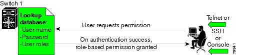
Local Authentication
The system maintains the user name and password locally and stores the password information in encrypted form. You are authenticated based on the locally stored information (see Figure 14-1).
Figure 14-1 Local Authentication
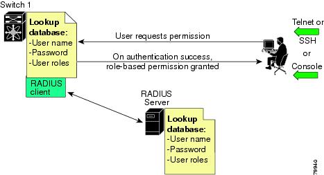
RADIUS Authentication
Cisco MDS 9000 Family switches provide remote authentication through RADIUS servers. You can also configure multiple RADIUS servers, and each server is tried in the order specified.
RADIUS protocols support one-time password (OTP) schemes that all switches can make use of for authentication purposes (see Figure 14-2).
Figure 14-2 RADIUS Authentication
Role-Based Authorization
By default, two roles exist in all switches:
•
•
The two default roles cannot be changed or deleted. Vendor-specific attributes (VSAs) contain the user profile information used by the switch. To use this option, configure the VSAs on the RADIUS servers.
Accounting
Accounting refers to the log that is kept for each management session in a switch. This information may be used to generate reports for troubleshooting purposes and user accountability. Accounting can be implemented locally and remotely (using RADIUS).
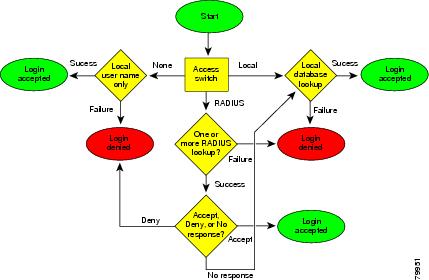
Authentication and Authorization Process
The following steps explain the authorization and authentication process. Figure 14-3 shows a flow chart of the process.
Step 1
Step 2
Note
Step 3
Step 4
Figure 14-3 Switch Authorization and Authentication Flow
Configuring CLI Authentication Methods
You can configure remote and local authentication for Telnet, SSH, or console access. These commands are restricted to privileged users as determined by your administrator.
Setting AAA Authentication
You can individually set authentication options for console or Telnet (and SSH) access using the aaa authentication login command. Local authentication is always disabled by default (see the "Authentication and Authorization Process" section).
To configure the authentication option, follow these steps:
Enabling or Disabling Telnet Access
You can use the telnet server enable command to enable Telnet access to the switch. By default, this service is enabled.
To enable or disable Telnet access to the switch, follow these steps:
Displaying CLI Authentication Commands
The show authentication command displays the configured authentication methods. See Example 14-1.
Example 14-1 Displays Authentication Information
switch# show authenticationauthentication method:noneconsole:not enabledtelnet/ssh:not enabledauthentication method:radiusconsole:not enabledtelnet/ssh:not enabledauthentication method:localconsole:enabledtelnet/ssh:enabledThe show telnet server command displays the state of the Telnet access configuration. See Example 14-2.
Example 14-2 Displays Telnet Server Details
switch# show telnet servertelnet service enabledConfiguring Role-Based CLI Authorization
Switches in the Cisco MDS 9000 Family perform authentication based on roles. Role-based authorization limits access to switch operations by assigning users to roles. This kind of authentication restricts you to management operations based on the roles to which you have been added.
When you execute a command, perform command completion, or obtain context sensitive help, the switch software allows the operation to progress if you have permission to access that command.
To configure a new role or to modify the profile for an existing role, follow these steps:
Each role can contain multiple users and each user can be part of multiple roles. For example, if role1 users are only allowed to perform configuration commands, and role2 users are only allowed to perform debug commands, then if Joe belongs to both role1 and role2, he can perform configuration as well as debug commands.
Note
Tip
Configuring Rules and Features for Each Role
The rule command specifies operations that can be performed by a specific role. Each rule consists of a rule number, a rule type (permit or deny), a command type (for example, config, clear, show, exec, debug), and an optional feature name (for example, FSPF, zone, VSAN, fcping, interface).
The user-specified rule number determines the order in which the rules are applied. For example, rule 1 is applied before rule 2 which is applied before rule 3 etc.
Note
To configure a new role or to modify the profile for an existing role, follow these steps:
In Step 3, rule 1 is applied first, thus permitting all config commands to sangroup users. Rule 2 is applied next, denying FSPF configuration to sangroup users. As a result, sangroup users can perform all other config commands, except fspf configuration commands.
Note
Configuring the VSAN Policy
You can configure a role so that it only allows commands to be performed for a selected set of VSANs. By default, the VSAN policy of a role is permit. In other words, the role can perform commands configured by the rule command in all VSANs. In order to selectively allow VSANs for a role, the VSAN policy needs to be set to deny and then the appropriate VSANs need to be permitted.
To configure a new role or to modify the VSAN policy for an existing role, follow these steps:
Note
Tip
Displaying Role-Based CLI Information
Use the show role command to display rules configured on the switch including those rules that have not yet been committed to persistent storage. The rules are displayed by rule number and are based on each role. All roles are displayed even if role name is not specified. See Example 14-3.
Example 14-3 Displays Information for All Roles
switch# show roleRole: network-adminDescription: Predefined Network Admin group. This role cannot be modifiedAccess to all the switch commandsRole: network-operatorDescription: Predefined Network Operator group. This role cannot be modifiedAccess to Show commands and selected Exec commandsRole: TechDocsvsan policy: permit (default)Role: sangroupDescription: SAN management groupvsan policy: denyPermitted vsans: 10-30-----------------------------------------Rule Type Command-type Feature-----------------------------------------1. permit config *2. deny config fspf3. permit debug zone4. permit exec fcpingConfiguring CLI User Profiles
Every Cisco MDS 9000 Family switch user has related NMS information stored by the system. Your authentication information, user name, user password, password expiration date, and role membership are stored in your user profile. The CLI commands explained in this section enable you to create users and modify the profile of an existing user.These commands are restricted to privileged users as determined by your administrator.
Creating or Updating Users
The switches use the same command (username) to create a user and to update an existing user. The expire option determines the date on which the user account is disabled. The date is specified in the YYYY-MM-DD format. By default, the user account does not expire unless you explicitly configure it to expire.
Tip
Note
To configure a new user or to modify the profile of an existing user, follow these steps:
Note
Logging out CLI Users
To log out another user on the switch, use the clear user command.
switch# clear user vsamswitch#In this example, the user named vsam is logged out from the switch.
Displaying User Profile Information
Use the show user-account command to display configured information about user accounts. See Examples 14-4 to 14-6.
Example 14-4 Displays All Users
switch# show usersadmin pts/7 Jan 12 20:56 (10.77.202.149)admin pts/9 Jan 12 23:29 (modena.cisco.com)admin pts/10 Jan 13 03:05 (dhcp-171-71-58-120.cisco.com)admin pts/11 Jan 13 01:53 (dhcp-171-71-49-49.cisco.com)Example 14-5 Displays Information for a Specified User
switch# show user-account user1user:user1this user account has no expiry dateroles:network-operatorno password set. Local login not allowedRemote login through RADIUS is possibleExample 14-6 Displays Information for All Users
switch# show user-accountshow user-accountuser:adminthis user account has no expiry dateroles:network-adminuser:usamexpires on Sat May 31 00:00:00 2003roles:network-admin network-operatoruser:msamthis user account has no expiry dateroles:network-operatoruser:user1this user account has no expiry dateroles:network-operatorno password set. local login not allowedRemote login through RADIUS is possibleConfiguring CLI Accounting Parameters
Accounting refers to the log information that is kept for each management session in a switch. This information may be used to generate reports for troubleshooting purposes and user accountability. Accounting can be implemented locally or remotely (using RADIUS).
Setting the Accounting Log Size
The aaa accounting logsize command sets the size limit of the accounting log file in persistent storage. The default is 15,000 bytes.
To set the log file size, follow these steps:
Step 1
Enters configuration mode.
Step 2
Sets the size of the log file on the local disk. The default is 15,000 bytes.
Enabling RADIUS Accounting
To enable RADIUS accounting in a switch, follow these steps:
You can clear the RADIUS accounting configuration by issuing the no aaa accounting method radius command.
Tip
Note
Displaying Accounting Configuration
The show accounting command displays configured accounting information. See Examples 14-7 to 14-9.
Example 14-7 Displays Configured Accounting Parameters.
switch# show accounting configRADIUS accounting not enabledlocal accounting enabledExample 14-8 Displays Configured Log Size.
switch# show accounting logsizemaximum local accounting log size:29000Example 14-9 Displays the Entire Log File.
switch# show accounting logTue Jan 15 06:03:24 1980:update:::Created interface vsan1Tue Jan 15 06:15:08 1980:start:/dev/pts/0_316764908:adminTue Jan 15 07:26:10 1980:stop:/dev/pts/0_316764908:admin:vsh exited normallyTue Jan 15 07:46:40 1980:update:/dev/ttyS0_316753046:admin:Alias test is createdon VSAN 1Tue Jan 15 07:46:40 1980:update:/dev/ttyS0_316753046:admin:Alias test is removedon VSAN 1Tue Jan 15 08:01:57 1980:update:/dev/ttyS0_316753046:admin:in-order delivery guarantee settings changed in-order guarantee:yesTue Jan 15 08:02:31 1980:update:/dev/ttyS0_316753046:admin:Enabled IP routingTue Jan 15 08:09:51 1980:update:/dev/ttyS0_316753046:admin:Alias test is createdon VSAN 1Tue Jan 15 08:09:52 1980:update:/dev/ttyS0_316753046:admin:Alias test is removedon VSAN 1Tue Jan 15 08:11:30 1980:update:/dev/ttyS0_316753046:admin:Zone test is createdon VSAN 1...Sat Jan 19 22:16:06 1980:update:/dev/pts/0_317167691:admin:Zone cisco is removedon VSAN 1Sat Jan 19 22:56:49 1980:stop:/dev/pts/0_317167691:admin:vsh exited normallySun Jan 20 17:07:50 1980:start:snmp_317236070_10.77.202.149:publicSun Jan 20 17:07:50 1980:stop:snmp_317236070_10.77.202.149:public:Mon Jan 21 03:38:03 1980:start:/dev/pts/0_317273883:adminMon Jan 21 04:08:25 1980:stop:/dev/pts/0_317273883:admin:vsh exited normallyMon Jan 21 06:43:49 1980:start:/dev/pts/0_317285029:adminMon Jan 21 06:44:38 1980:stop:/dev/pts/0_317285029:admin:vsh exited normallyMon Jan 21 07:24:16 1980:start:/dev/pts/0_317287456:adminRecovering Administrator Password
An administrator can recover a password from a local console connection.
The password recovery procedure must be performed on the supervisor module that becomes the active supervisor module after the recovery procedure is completed. To ensure the other supervisor module does not become the active module, you have two options:
•
•
Note
To recover a administrator's password, follow these steps:
Step 1
switch# reloadThe supervisor is going down for reboot NOW!Step 2
Ctrl-]switch(boot)#Step 3
switch(boot)# config terminalStep 4
switch(boot-config)# admin-password passwordStep 5
switch(boot-config)# exit
switchboot#
Step 6
switch(boot)# load bootflash:system.imgStep 7
switch# copy running-config startup-config
Configuring RADIUS Authentication
You can configure RADIUS query parameters. These commands are restricted to privileged users as determined by your administrator.
Setting the RADIUS Server Address
You can add up to five (5) RADIUS servers using the radius-server host command. You can configure a RADIUS server to be a primary server so it is always contacted first. If you have not configured a primary server, the RADIUS servers are tried in the order they were configured.
To specify the RADIUS server address and the options, follow these steps:
Setting the RADIUS Preshared Key
You need to configure the RADIUS preshared key to authenticate the switch to the RADIUS server. The length of the key is restricted to 65 characters and can include any printable ASCII characters (white spaces are not allowed). You can configure a global key to be used for all RADIUS server configurations on the switch. You can override this global key assignment by explicitly using the key option in the radius-server host command.
To set the RADIUS preshared key, follow these steps:
Setting the RADIUS Server Time-Out Interval
To specify the time between retransmissions to the RADIUS servers, follow these steps:
You can revert the retransmission time to its default by issuing the no radius-server timeout command.
Setting Iterations of the RADIUS Server
By default, a switch retries a RADIUS server connection only once. This number can be configured. The maximum is five retries per server. You can revert the retry number to its default by issuing the no radius-server retransmit command.
To specify the number of times that RADIUS servers should try to authenticate a user, follow these steps:
The worst case cumulative response or timeout latency from RADIUS servers for authentication should not be more than 50 sec. For example in the following configuration:
radius-server timeout 5radius-server retransmit 3radius-server host A authenticationradius-server host B authenticationThe worst case cumulative response or timeout latency will be:
(5+1)*3 + (5+1)*3 = 36^^^^^^^^ ^^^^^^^^^ ^^^^^server A server B total
Note
Defining Vendor-Specific Attributes
The Internet Engineering Task Force (IETF) draft standard specifies a method for communicating vendor-specific attributes (VSAs) between the network access server and the RADIUS server. The IETF uses attribute 26. VSAs allow vendors to support their own extended attributes that are not suitable for general use. The Cisco RADIUS implementation supports one vendor-specific option using the format recommended in the specification. The Cisco vendor ID is 9, and the supported option is vendor type 1, which is named cisco-avpair. The value is a string with the following format:
protocol : attribute sep value *Where protocol is a Cisco attribute for a particular type of authorization, and sep is = for mandatory attributes, and * is for optional attributes.
When you use RADIUS servers to authenticate yourself to a Cisco MDS 9000 Family switch, the RADIUS protocol directs the RADIUS server to return user attributes, like authorization information, along with authentication results. This authorization information is specified through VSAs.
VSA Format
The following VSA protocol options are supported:
•
•
The following attributes are supported:
•
Cisco-AVPair = "shell: roles = "network-admin vsan-admin" "
•
Authorization Process
The RADIUS based authorization process is as follows:
Step 1
Step 2
•
•
•
•
Step 3
Displaying RADIUS Server Details
Use the show radius-server command to display all configured RADIUS server parameters (see Example 14-10).
Note
Example 14-10 Displays Configured RADIUS Information
switch# show radius-serverGlobal RADIUS shared secret:Myxgqcretransmission count:5timeout value:10following RADIUS servers are configured:myradius.cisco.users.com:available for authentication on port:1812available for accounting on port:1813172.22.91.37:available for authentication on port:1812available for accounting on port:1813RADIUS shared secret:23MHcUnD10.10.0.0:available for authentication on port:1812available for accounting on port:1813RADIUS shared secret:hostkey----> for administrators onlyConfiguring SSH Services
The Telnet service is enabled by default on all Cisco MDS 9000 Family switches. Before enabling the SSH service, generate a host key pair. To generate a host key, use the ssh key command (see the "Generating an SSH Host Key Pair" section).
Enabling SSH Service
By default, the SSH service is disabled. To enable SSH service, issue the ssh server enable command.
To enable or disable the SSH service, follow these steps:
Generating an SSH Host Key Pair
Be sure to have an SSH host key pair with the appropriate version before enabling the SSH service. The SSH service accepts three types of key pairs for use by SSH versions 1 and 2. Generate the SSH host key pair according to the SSH client version used. The number of bits specified for each key pair ranges from 768 to 2048.
•
•
•
To generate the SSH host key pair, follow these steps:
Using the force Option
If the SSH key pair option is already generated for the required version, use the force option to overwrite the previously generated key pair.
To overwrite the previously generated key pair, follow these steps:
Clearing SSH Hosts
To manually clear trusted SSH host entries, issue the clear ssh hosts command at the switch prompt:
Example 14-11 Clearing Configured SSH Hosts
switch# clear ssh hosts
switch#
This command clears all SSH hosts.
Displaying SSH Protocol Status
Use the show ssh server command to display the status of the SSH protocol (enabled or disabled) and the versions that are enabled for that switch. See Example 14-12.
Example 14-12 Displays SSH Protocol Status
switch# show ssh server
ssh is enabled
version 1 enabled
version 2 enabled
Use the show ssh key command to display the host key pair details for the specified key or for all keys, if no key is specified. See Example 14-13.
Example 14-13 Displays Host Key Pair Details
switch# show ssh key
rsa1 Keys generated:Sun Jan 13 07:16:26 1980
1024 35fingerprint:1024 67:76:02:bd:3e:8d:f5:ad:59:5a:1e:c4:5e:44:03:07could not retrieve rsa key informationdsa Keys generated:Sun Jan 13 07:40:08 1980ssh-dss AAAAB3NzaC1kc3MAAABBAJTCRQOydNRel2v7uiO6Fix+OTn8eGdnnDVxw5eJs5OcOEXOyjaWcMMYsEgxc9ada1NElp8Wy7GPMWGOQYj9CU0AAAAVAMCcWhNN18zFNOIPo7cU3t7d0iEbAAAAQBdQ8UAOi/Cti84qFb3kTqXlS9mEhdQUo0lHcH5bw5PKfj2Y/dLR437zCBKXetPj4p7mhQ6Fq5os8RZtJEyOsNsAAABAA0oxZbPyWeR5NHATXiyXdPI7j9i8fgyn9FNipMkOF2Mn75Mi/lqQ4NIq0gQNvQOx27uCeQlRts/QwI4q68/eaw==fingerprint:512 f7:cc:90:3d:f5:8a:a9:ca:48:76:9f:f8:6e:71:d4:aeSNMP Security
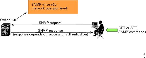
SNMP is an application layer protocol that facilitates the exchange of management information between network devices. In all Cisco MDS 9000 Family switches, three SNMP versions are available: SNMPv1, SNMPv2c, and SNMPv3 (see Figure 14-4).
Figure 14-4 SNMP Security
Note
SNMP users are different from CLI users. SNMP users also have role-based authentication for roles and authorization purposes.
SNMP Version 1 and Version 2c
SNMPv1 and SNMPv2c use a community string match for user authentication. Community strings provided a weak form of access control in earlier versions of SNMP. SNMPv3 provides much improved access control using strong authentication and should be preferred over SNMPv1 and SNMPv2c wherever it is supported.
SNMP Version 3
SNMPv3 is an interoperable standards-based protocol for network management. SNMPv3 provides secure access to devices by a combination of authenticating and encrypting frames over the network. The security features provided in SNMPv3 are:
•
•
•
SNMPv3 provides for both security models and security levels. A security model is an authentication strategy that is set up for a user and the role in which the user resides. A security level is the permitted level of security within a security model. A combination of a security model and a security level determines which security mechanism is employed when handling an SNMP packet.
Restricting Switch Access
You can restrict access to a Cisco MDS 9000 Family switch using IP Access Control Lists (IP-ACLs). See the "IP Access Control Lists" section.
Group-Based SNMP Access
Note
SNMP access rights are organized by groups. Each group in SNMP is similar to a role through the CLI. Each group is defined with three accesses: read access, write access, and notification access. Each access can be enabled or disabled within each group.
You can begin communicating with the agent once the your user name is created, your roles are set up by your administrator, and you are added to the roles.
Note
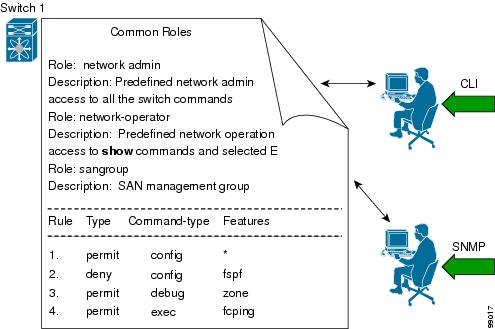
Configuring Common Roles
From Release 1.2(x), CLI and SNMP in all switches in the Cisco MDS 9000 Family use the common roles database. This database contains any role that is created using CLI or SNMP. You can use SNMP to modify a role that was created using CLI and vice versa (see Figure 14-5).
Figure 14-5 Common Roles Database
Each role in SNMP is the same as a role created or modified through the CLI (see "Configuring Role-Based CLI Authorization" section).
Each role in the Common Role database can be restricted to one or more VSAN as required.
You can create new roles or modify existing roles using SNMP or the CLI.
•
•
Creating and Modifying Users
You can create users or modify existing users using SNMP or the CLI.
•
Note
The password is limited to a minimum of 8 characters and a maximum of 64 characters.
Tip
•
By default only two roles are available in a Cisco MDS 9000 Family switch—network-operator and network-admin. You can also use any role that is configured in the Common Roles database (see the "Configuring Common Roles" section).
To create or modify SNMP users using the CLI, follow these steps:
Note
Forcing Identical SNMP and CLI Passwords
You can force the SNMPv3 password and the CLI password to be the same. You must know the SNMPv3 password to change the password using the CLI. Use CLI password to synchronize the SNMP password The password is limited to a minimum of 8 characters and a maximum of 64 characters.
Caution
To modify the secret key for an SNMPv3 user, refer to RFC2574.
To update the SNMPv3 password from the CLI, follow these steps:
Assigning Users to Roles
Once the user and the role are created, the administrator should configure an entry in the vacmSecurityToGroupTable to add the configured user to a configured role.
To assign users to roles through SNMP, refer to RFC2575.
To assign users to roles through the CLI, refer to the procedure specified in the "Creating and Modifying Users" section.
Adding or Deleting Communities
You can configure read-only or read-write access for SNMP users by using the snmp-server community CLI command. Use the no form of the command to delete the configured community. Refer to RFC2576.
To create an SNMPv1 or SNMPv2c community, follow these steps:
Displaying SNMP Security Information
Use the show snmp commands to display configured SNMP information (see Example 14-14 and 14-16).
Example 14-14 Displays SNMP User Details
switch# show snmp userUser Group Auth Priv____ _____ ____ ____steve network-admin md5 dessadmin network-admin md5 desstever network-operator md5 desExample 14-15 Displays SNMP Community Information
switch# show snmp communityCommunity Access--------- ------private rwpublic rov93RACqPNH roExample 14-16 Displays SNMP Host Information
switch# show snmp hostHost Port Version Level Type SecName____ ____ _______ ______ ____ ______171.16.126.34 2162 v2c noauth trap public171.16.75.106 2162 v2c noauth trap public...171.31.58.97 2162 v2c auth trap public...Displaying SNMP Counter Information
The show snmp command displays counter information for SNMP contact, location, and packet settings. This command provides information that is used entirely by the Cisco MDS 9000 Family Fabric Manager (refer to the Cisco MDS 9000 Family Fabric Manager User Guide). See Example 14-17.
Example 14-17 Displays SNMP
switch# show snmpswitch# show snmpsys contact:sys location:1631 SNMP packets input0 Bad SNMP versions0 Unknown community name0 Illegal operation for community name supplied0 Encoding errors64294 Number of requested variables1 Number of altered variables1628 Get-request PDUs0 Get-next PDUs1 Set-request PDUs152725 SNMP packets output0 Too big errors1 No such name errors0 Bad values errors0 General errorsCommunity Access--------- ------public rwUser Group Auth Priv____ _____ ____ ____admin network-admin md5 noDefault Security Settings
Table 14-2 lists the default settings for all security features in any switch.