
-
Cisco MDS 9000 Family Fabric Manager User Guide, Release 1.2(1a) (Updated: Sep 25, 2003)
-
New and Changed Information
-
Index
-
Preface
-
Getting Started with Cisco Fabric Manager
-
Using Cisco Fabric Manager and Device Manager
-
Managing Zones and Zone Sets
-
Managing VSANs
-
Managing Administrator Access
-
Managing Software and Configuration Files
-
Managing Interfaces
-
Managing Events and Alarms
-
Managing the System and Components
-
Managing Fibre Channel Routing and FSPF
-
Managing IP Storage Services
-
Configuring IP Filters
-
Managing SPAN
-
Managing Advanced Features
-
Table Of Contents
Controlling In-Band Management Connectivity
Configuring IP Routing for Management Traffic
Managing IPFC Connectivity with Multiple VSANs
Viewing IP Address Information
Enabling or Disabling IP Forwarding
Viewing TCP Information and Statistics
Viewing UDP Information and Statistics
Managing VSANs
VSANs (virtual SANs) allow you to separate devices that are physically connected to the same fabric, and thus provide higher security and greater scalability in the network fabric. When you create VSANs, you are creating multiple logical SANs over a common physical infrastructure. After creating VSANs, you must establish IP static routes between the network segments if you are using the IP over Fibre Channel (IPFC) protocol to manage your Cisco MDS 9000 Family switches.
The Fabric Manager allows you to configure VSANs on multiple Cisco 9000 switches. The Device Manager allows you to configure VSANs on a single Cisco 9000 switch.
Note
For information about VSANs and configuring them using the command-line interface (CLI), refer to the Cisco 9000 Family Configuration Guide.
You can manage Cisco MDS 9000 Family switches through Ethernet connections to the management interface (mgmt 0) of each switch or by using the IPFC protocol. To use IPFC, you connect to a switch using the Ethernet management interface and establish routes from that switch to the other switches over the Fibre Channel network. When you segment the Fibre Channel network using VSANs, you must establish static routes between the network segments.
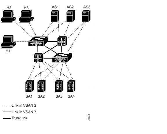
Figure 4-1 shows a physical Fibre Channel network with two VSANs. VSAN 2 is connected by dashed lines and VSAN 7 is connected by solid lines.
Figure 4-1 Configuring VSANs
VSAN 2 includes the H1 and H2 hosts, the AS2 and AS3 application servers, and the SA1 and SA4 storage arrays. VSAN 7 connects H3, AS1, SA2, and SA3. The four switches in this network are interconnected by trunk links that carry both VSAN 2 and VSAN 7 traffic.
VSAN 1 is the default VSAN for Cisco MDS 9000 Family switches. All ports are assigned by default to VSAN 1. VSAN 4094 is called the isolated VSAN. When a VSAN is deleted, any ports in that VSAN are moved to VSAN 4094.
Note
We recommend that you delete or move all the ports in a VSAN before deleting the VSAN.
VSANs are enabled through trunking, which enables interconnect ports to transmit and receive frames in more than one VSAN over a single physical link, using the Extended Inter-Switch Link (EISL) protocol. The trunking protocol is enabled by default, and if disabled on a switch, no ports on that switch or directly connected to the switch will support the use of VSANs.
By default, the trunk mode is enabled on all Fibre Channel interfaces, but can be disabled on a port-by-port basis. When connected to a third-party switch, the trunk mode configuration has no effect—the ISL is always in a trunking disabled state.
Each Fibre Channel interface has an associated trunk-allowed VSAN list. This list determines the VSANs that are supported on each interface. By default, the entire range of VSANs from 1 through 4093 are allowed on any interface. You can restrict an interface to the use of a specific set of VSANs, which prevents traffic from any other VSAN being transmitted on the interface.
Procedures for managing VSANs include:
Adding and Configuring VSANs
To add and configure VSANs, perform the following steps.
Step 1
From the Fabric Manager, choose FC > VSAN from the menu tree, OR
From Device Manager, choose the VSAN option from the FC menu or click the VSAN icon on the toolbar.The Fabric Manager's Information pane displays VSAN attributes for multiple switches. The VSAN dialog box in the Device Manager displays VSAN general attributes for a single switch.
Step 2
From Fabric Manager, click Create Row on the Information pane toolbar, OR
From Device Manager, click Create on the VSAN dialog box.You see the Create dialog box.
Step 3
Complete the fields on this dialog box and click OK to add the VSAN.
Note
You can access the field descriptions for the windows or dialog boxes in this procedure in the Reference section of the Fabric Manager or Device Manager help systems.
Controlling In-Band Management Connectivity
The Fabric Manager allows you to configure and monitor IP traffic on multiple Cisco MDS 9000 Family switches. The Device Manager allows you to configure and monitor IP traffic on a single Cisco 9000 switch.
Cisco MDS 9000 Family switches support both out-of-band and in-band management schemes. An Ethernet connection provides out-of-band management using Telnet, SSH or SNMP access. In-band IP management is also available using IP over Fibre Channel (IPFC). IPFC encapsulates IP packets into Fibre Channel frames so that management information can cross the Fibre Channel network without requiring a dedicated Ethernet connection to each switch. IP addresses are resolved to the Fibre Channel address through the Address Resolution Protocol (ARP).
Procedures for managing and viewing connectivity information include:
•
Configuring IP Routing for Management Traffic
•
Managing IPFC Connectivity with Multiple VSANs
•
Viewing IP Address Information
•
Enabling or Disabling IP Forwarding
•
Viewing TCP Information and Statistics
•
Viewing UDP Information and Statistics
Configuring IP Routing for Management Traffic
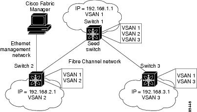
When using in-band network management over Fibre Channel links, you must ensure that a path exists from the seed switch, connected to the Cisco Fabric Manager over its Ethernet interface (mgmt0), and the other switches in the network fabric. See Figure 4-2.
Figure 4-2 IP Routing Between VSANs
To do this, make sure that the seed switch has a path to each VSAN. Each of the other switches can then be configured to use the seed switch as their default gateway. For example, in Figure 4-2, switch 1 is connected to VSAN 2 and VSAN 3, while switch 2 and switch 3 are configured to use switch 1 as their default gateway.
You can also configure static routes on a point-to-point basis from one switch to another. In this example, you would configure a static route on both switch 2 and switch 3 to switch 1.
Configuring an IP Route
To configure an IP route or identify the default gateway, perform the following steps.
Step 1
From the Device Manager, choose Routes from the IP menu.
You see the IP Routes window.
Step 2
To create a new IP route or identify the default gateway on a switch, click the Create button.
You see the Create IP Routes window.
Step 3
Complete the fields on this window and click OK to add an IP route.
Step 4
To configure a static route, enter the destination network ID and subnet mask in the Dest and Mask fields. To configure a default gateway, enter the IP address of the seed switch in the Gateway field.
Note
You can access the field descriptions for the windows or dialog boxes in this procedure in the Reference section of the Fabric Manager or Device Manager help systems.
Managing IPFC Connectivity with Multiple VSANs
To configure IPFC from the Device Manager, choose VSAN from the FC menu and click the General tab.
Note
You can access the field descriptions for the windows or dialog boxes in this procedure in the Reference section of the Fabric Manager or Device Manager help systems.
Viewing IP Address Information
To view IP addresses of the switches in the current fabric from the Fabric Manager, choose Switches from the menu tree.
The Information pane displays IP address information for multiple switches.
Note
You can access the field descriptions for the windows or dialog boxes in this procedure in the Reference section of the Fabric Manager or Device Manager help systems.
Enabling or Disabling IP Forwarding
To view or change the IP forwarding configuration of the switches in the current fabric, perform the following steps.
Step 1
Choose IP > Forwarding from the Fabric Manager menu tree.
Step 2
To enable IP forwarding for a specific switch, click the RoutingEnabled check box.
Note
You can access the field descriptions for the windows or dialog boxes in this procedure in the Reference section of the Fabric Manager or Device Manager help systems.
Viewing TCP Information and Statistics
To view TCP information from the Device Manager, choose Mgmt TCP/UDP from the IP menu.
To monitor TCP statistics from the Fabric Manager, choose IP > Mgmt Statistics from the menu tree and click the TCP tab. To monitor TCP statistics from the Device Manager, choose Statistics from the IP menu and view the TCP tab.
Note
You can access the field descriptions for the windows or dialog boxes in this procedure in the Reference section of the Fabric Manager or Device Manager help systems.
Viewing UDP Information and Statistics
To view User Datagram Protocol (UDP) information, from the Device Manager, choose Mgmt TCP/UDP from the IP menu and click the UDP tab.
To monitor UDP traffic from the Fabric Manager, choose IP > Mgmt Statistics from the menu tree and click the UDP tab. From Device Manager, choose Statistics from the IP menu and click the UDP tab.
The Fabric Manager Information pane displays TCP traffic information for multiple switches. The Device Manager dialog box displays information for a single switch.
Note
You can access the field descriptions for the windows or dialog boxes in this procedure in the Reference section of the Fabric Manager or Device Manager help systems.
Viewing IP Statistics
To monitor IP statistics from the Fabric Manager, choose IP >Mgmt Statistics from the menu tree and click the IP tab. From Device Manager, select Statistics from the IP menu and click the IP tab.
The Fabric Manager Information pane displays IP statistics for multiple switches. The Device Manager dialog box displays information for a single switch.
Note
You can access the field descriptions for the windows or dialog boxes in this procedure in the Reference section of the Fabric Manager or Device Manager help systems.
Viewing ICMP Statistics
To monitor statistics for ICMP packets received, select IP > Mgmt Statistics from the menu tree and click the ICMP In tab. To monitor statistics for ICMP packets transmitted from the Fabric Manager, select IP > Mgmt Statistics from the menu tree and click the ICMP Out tab.
To monitor ICMP statistics from Device Manager, select Statistics from the IP menu and click the ICMP tab.
The Fabric Manager Information pane displays information for multiple switches. The Device Manager dialog box displays information for a single switch.
In the Device Manager, a prefix (In or Out) identifies whether the packets are received or transmitted. In the Fabric Manager, separate tabs on the Information pane are provided for incoming and outbound ICMP traffic and this prefix is omitted.
Note
You can access the field descriptions for the windows or dialog boxes in this procedure in the Reference section of the Fabric Manager or Device Manager help systems.
Monitoring SNMP Traffic
To monitor SNMP traffic statistics from the Fabric Manager, select IP >Mgmt Statistics from the menu tree and click on the SNMP tab. To monitor SNMP traffic from Device Manager, select Statistics from the IP menu and click the SNMP tab.
The Fabric Manager Information pane displays information for multiple switches. The Device Manager dialog box displays information for a single switch.
Note
You can access the field descriptions for the windows or dialog boxes in this procedure in the Reference section of the Fabric Manager or Device Manager help systems.

 Feedback

