-
Cisco MDS 9000 Family Configuration Guide, Release 1.0(2a)
-
Index
-
Preface
-
Product Overview
-
Before You Begin
-
Initial Configuration
-
Configuring High Availability
-
Software Images
-
Managing Modules
-
Managing System Hardware
-
Configuring and Managing VSANs
-
Configuring Interfaces
-
Configuring Trunking
-
Configuring PortChannels
-
Configuring and Managing Zones
-
Managing FLOGI, Name Server, and RSCN Databases
-
Configuring System Security and AAA Services
-
Configuring Fibre Channel Routing Services and Protocols
-
Configuring IP Services
-
Configuring Call Home
-
Configuring Domain Parameters
-
Configuring Traffic Management
-
Configuring System Message Logging
-
Discovering SCSI Targets
-
Monitoring Network Traffic Using SPAN
-
Advanced Features and Concepts
-
Configuring Fabric Configuration Servers
-
Monitoring System Processes and Logs
-
 Feedback
Table Of Contents
Nondisruptive and Disruptive Upgrades
Essential Upgrade Requirements
Formatting Flash Disks and File Systems
Making a Quick Software Upgrade
Upgrading Switches with a Single Supervisor Module
Upgrading Switches with Dual Supervisor Modules
Upgrading Software Images on Modules
Comparing the Kickstart and System Images
Specifying Kickstart and System Images
Clearing SYSTEM Variable Contents
Recovering a Corrupted Bootflash
Recovery from the loader> Prompt
Recovery from the switch(boot)# Prompt
Recovery for Switches with Dual Supervisor Modules
Programming Supervisor Module BIOS
Programming Switching Module BIOS
Software Images
This chapter describes how to install and upgrade software images. The software image upgrade procedure is dependent on the following factors:
•
Software images—The kickstart and system image files reside in the Cisco MDS 9000 Family software.
•
•
•
A combination of these factors determine if the upgrade is disruptive (traffic is affected) or nondisruptive (traffic is not affected).
This chapter includes the following sections:
•
•
•
•
•
•
•
•
•
•
About Software Images
During a software upgrade process, the current startup configuration file is left untouched. The current startup configuration file can be used after any migration. The startup configuration is translated to a format that is understood by the new version upon restart.
Each switch in the Cisco MDS 9000 Family is shipped with a Cisco Multilayer intelligent SAN operating system called SAN-OS and two images—the kickstart image and the system image:
•
•
The images and variables are important factors in any upgrade procedure. You must specify the variable and the image to upgrade your switch.
To upgrade to a different software version, you need to download two new image files—kickstart and system to a local switch and change the relevant configuration SYSTEM and KICKSTART variables to point to the new image. The next time the switch is rebooted, the new image files are used.
Both images are not always required for each upgrade. To verify if the kickstart image needs to be upgraded, see the "Upgrading Software Images on Modules" section.
A software image is identified by its software version and ID. The version and ID are important factors in comparing and determining the kickstart image or the system image files.
About Flash Devices
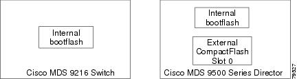
Every switch in the Cisco MDS 9000 Family contains one internal bootflash: that resides in the supervisor module. Cisco MDS 9500 Series directors contain an additional external CompactFlash called slot0: (see Figure 5-1 and Figure 5-2).
Figure 5-1 Flash Devices in the Cisco MDS 9000 Family
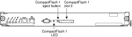
Figure 5-2 External CompactFlash in the Cisco MDS 9000 Supervisor Module
Nondisruptive and Disruptive Upgrades
The Cisco MDS SAN-OS software, designed for mission-critical high availability environments, provides the ability to upgrade software without any disruptions. To realize the benefits of nondisruptive upgrades on the Cisco MDS 9509 Director, it is highly recommended that you install dual supervisor modules.
However, in some cases the software upgrades may be disruptive. You can determine and plan for these exception scenarios by issuing the following commands:
•
•
These exception scenarios can occur under the following conditions:
•
•
•
Essential Upgrade Requirements
Before attempting to migrate to any software image version, follow these guidelines:
•
•
•
–
–
•
When copying a new image to your switch, you should confirm that the image was not corrupted during the copy process. Use the show version image command to verify successful that the required image was copied successfully.
excal-113# show ver image bootflash:esystem-281image name: m9200-ek9-mz.1.0.0.281.binsystem: version 1.0(2a) [build 1.0(0.281)]compiled: 11/21/2002 6:00:00
Note
•
Formatting Flash Disks and File Systems
By formatting a flash disk or a file system, you are essentially clearing out the contents of the disk or the file system and restoring it to its factory-shipped state.
Initializing bootflash:
When a switch is shipped, the init system command is already performed and you do not need to issue it again. Initializing the switch resets the entire internal disk and restores it to the original factory-shipped state. The internal disk is composed of several file systems with bootflash: being one of them. All files in bootflash: are erased and you must download the system and kickstart images again. If you issue an init system command at any time, you don't have to format the bootflash: again since bootflash: is automatically formatted.
If bootflash: is found corrupted during a boot sequence, you will see the following message:
ERROR:bootflash: has unrecoverable error; please do "format bootflash:"Use the format bootflash: command to only format the bootflash: filesystem.
If you issue the format bootflash: command, you need to download the kickstart and system images again.
Formatting Slot0:
Be sure to format an external CompactFlash device before using it to save files or images.
You can verify if the external CompactFlash device is formatted by inserting it into slot0: and issuing the dir slot0: command.
•
•
Device unavailableIn this case, you need to format the CompactFlash device using the format slot0: command.
Note
Making a Quick Software Upgrade
To perform a quick (disruptive) upgrade on any switch, follow these steps:
Step 1
Step 2
Step 3
The switch remains operational while the image file is copied.
Note
•
switch# copy tftp://<server IP address>/<file name in TFTP> <destination file name
as desired>
For example:
switch# copy tftp://10.1.7.2/system.img bootflash:system.img
Note
•
switch# copy tftp://<server IP address>/<file name in TFTP> slot0:system.imgFor example:
switch# copy tftp://10.1.7.2/system.img slot0:system.img
Note
Step 4
switch# dir bootflash:
total 100756
drwxrwxrwx 2 admin 1024 Fri Sep 27 17:35:13 2002 .sshdrwxrwxrwx 2 admin 1024 Fri Sep 27 17:35:13 2002 .ssh2-rw-r--r-- 1 admin 13636096 Fri Sep 20 19:58:56 2002 kickstart-233b-rw-rw-rw- 1 admin 14340096 Fri Sep 27 17:28:41 2002 kickstart-240-rw-r--r-- 1 admin 19280051 Fri Sep 20 20:02:33 2002 system-233b-rw-rw-rw- 1 admin 21917189 Fri Sep 27 17:29:51 2002 system-240drwxr-xr-x 2 admin 3072 Tue Oct 01 10:54:18 2002 logs-rwxr-xr-x 1 admin 636579 Mon Sep 30 05:32:42 2002 rdldrwxr-xr-x 2 admin 1024 Mon Sep 30 05:37:55 2002 src124688384 bytes total used311350272 bytes free459779072 bytes availableStep 5
switch# config terminalStep 6
switch(config)# boot system system.imgThe switch updates the SYSTEM environment variable to reflect the new image file in the specified Flash device.
Step 7
switch(config)# boot kickstart kickstart.imgIssue the following command if you are booting from the CompactFlash device (slot0:).
switch(config)# boot kickstart slot0:kickstart.imgThe switch replaces the existing KICKSTART environment variable.
Step 8
switch(config)# exit
Note
Step 9
switch# copy running-config startup-config[########################################] 100%You see the progress bar.
Step 10
switch# reloadThis command will reboot the system. (y/n)? yThe reload command reboots the switch. Use the reload command after the configuration information is saved to the startup configuration.
Upgrading Switches with a Single Supervisor Module
To perform a nondisruptive upgrade on a switch with a single supervisor module, follow these steps:
Step 1
Step 2
switch# show version compatibility bootflash:system.imgVersion comparison between /bootflash/system.img and running-image:Mod No Mod Type SRG Compare Result 1 LC Linecard version is compatible 2 LC Linecard version is compatible 3 LC Linecard version is compatible 4 LC Linecard version is compatible 6 SUP Non-Disruptive upgrade is possible 7 LC Linecard version is compatible 8 LC Linecard version is compatible 9 LC Linecard version is compatibleStep 3
switch# install sup bootflash:system.imgBeginning the install check...bootflash:/system.img and kickstart image...is compatible.bootflash:/system.img image...can be upgraded non-disruptively from current.Preliminary install check done.Beginning the install process.Parsing of versioning database successful.Preparing file system plan now...Done.Preparing upgrade group plan now...Done.Executing pre-uninstall scripts...Done.Updating the File System for installation...Done.Executing post-install scripts...Done.System Manager will restart the services according to upgrade plan..Done.Installation completed successfully.The install command only upgrades the system image.
If any errors occur during this process, the switch is reset to guarantee that the system does not continue with a half installed image. In this case, the switch uses the image that was saved in the SYSTEM environment variable prior to this installation procedure.
Upgrading Switches with Dual Supervisor Modules
A switch in the Cisco MDS 9500 Series has two supervisor modules—one in slot 5 (sup-1) and one in slot 6 (sup-2). When both supervisor modules power up at the same time, the module in slot 5 enters the active mode, while the second module in slot 6 enters the standby mode. To determine if the software images must be replaced, see the "Upgrading Software Images on Modules" section.
Note
Tip
To synchronize the software image, follow these steps:
Step 1
Step 2
a.
switch# show system auto-syncauto-sync is disabledauto-sync not startedIf the system auto-sync command is disabled (default), skip to Step 3.
If system auto-sync command is enabled, first disable this option by continuing with Step 2b.
b.
switch# config terminalc.
switch(config)# no system auto-sync imaged.
switch(config)# exitStep 3
switch# copy bootflash:system.img bootflash://sup-2/system.imgThis step shows you one example of copying an image file. If you need to copy the image similarly for other files (kickstart or BIOS), issue those commands as required.
Note
Step 4
a.
switch# config terminalb.
switch(config)# boot system bootflash:system.imgc.
switch(config)# exitd.
switch# show bootKICKSTART variable = bootflash:/kickstart.imgSYSTEM variable = bootflash:/kickstart.img;e.
switch# copy running-config startup-config
Note
Step 5
switch# reload module 6The command will reboot the standby supervisor module (y/n)? yabout to reset standby supVerify the status of the standby supervisor module by issuing the show system redundancy status command (see the "Displaying HA Information" section).
Step 6
switch# system switchoverThe newly-active supervisor module in slot 6 takes over as the active supervisor. The previously-active supervisor module in slot 5 reboots automatically. If you are on a Console port, you will see the rebooting messages as the supervisor modules come up.
Note
Step 7
Upgrading Software Images on Modules
A nondisruptive image upgrade has several dependencies. This section explains the dependencies for replacing software images in both the supervisor modules and the switching modules. Before attempting to upgrade software images, use these commands to determine if a software image upgrade is required.
To determine if nondisruptive software upgrade of a software image is possible, follow these steps:
Step 1
switch# show version compatibility bootflash:system.imgVersion comparison between /bootflash/system.img and running-image:Mod No Mod Type SRG Compare Result 1 LC Linecard version is compatible 2 LC Linecard version is compatible 3 LC Error in retrieving version information 4 LC Linecard version is compatible 5 SUP HA switchover will be possible <-----------standby supervisor 6 SUP Non-Disruptive upgrade is possible <----active supervisor 7 LC Linecard version is compatible 8 LC Linecard version is compatible 9 LC Not compatible <---------------------------------------module will be resetIn this case, a nondisruptive upgrade is possible and high availability (HA) switchover to the standby supervisor module is also possible. But switching module 9 will be reset after the upgrade is performed since the type may differ.
Step 2
switch# show version compatibility bootflash:system.imgVersion comparison between /bootflash/system.img and running-image:Mod No Mod Type SRG Compare Result1 LC Linecard version is compatible2 LC Linecard version is compatible3 LC Error in retrieving version information4 LC Linecard version is compatible5 SUP HA switchover will not be possible6 SUP Non-Disruptive upgrade is possible7 LC Linecard version is compatible8 LC Linecard version is compatible9 LC Linecard version is compatibleIn this case, the standby supervisor module reverts to a warm standby after a nondisruptive upgrade.
Note
To replace the image on switching modules see the "Power Cycling Modules" section.
Comparing the Kickstart and System Images
To display the current contents of the SYSTEM variable, enter the following command at the switch prompt:
switch# show boot
KICKSTART variable = slot0:kickstart.img
SYSTEM variable = bootflash:first-system.img;bootflash:second-system.img;The kickstart image and the system image list can be specified independent of each other. At boot time, an internal script discards all system images that are incompatible with the loaded kickstart image.
Specifying Kickstart and System Images
To specify the kickstart and system images in a switch, follow these steps:
Step 1
Step 2
switch# config terminalStep 3
switch(config)# boot kickstart bootflash:kickstart.img
Note
Step 4
switch(config)# boot system bootflash:first-system.imgStep 5
Step 6
switch(config)# boot system slot0:second-system.imgStep 7
switch(config)# exitStep 8
switch# copy running-config startup-configStep 9
switch# reloadThis command will reboot the system. (y/n)? yThe reload command reboots the system. Use the reload command after the configuration information is entered into a file and saved to the startup configuration.
Verifying Image Integrity
Use the show version image command to verify the integrity of the image before loading the images. This command can be used for both the system and kickstart images.
switch# show version image bootflash:bad.imgMd5 Verification Failed <--------------failure caseswitch(boot)# show version image bootflash:system.img <------------system imageimage name: m9500-sf1ek9-mzg.1.0.1.binsystem: version 1.0(2a)compiled: 11/16/2002 11:00:00switch(boot)# show version image bootflash:kickstart.img <-------------kickstart imageimage name: m9500-sf1ek9-kickstart-mzg.1.0.1.binkickstart: version 1.0(2a)compiled: 11/11/2002 10:00:00Clearing SYSTEM Variable Contents
To clear the current contents of the SYSTEM variable, enter the following command at the switch prompt:
switch(config)# no boot system switch# show bootsup-1KICKSTART variable = bootflash:/kick-281SYSTEM variable not setsup-2KICKSTART variable = bootflash:/kick-281SYSTEM variable not setTo clear the current contents of the SYSTEM variable in only one supervisor module, enter the following command at the switch prompt:
switch(config)# no boot system sup-2 switch# show bootsup-1KICKSTART variable = bootflash:/kickstart.imgSYSTEM variable = bootflash:/system.imgsup-2KICKSTART variable = bootflash:/kickstart.imgSYSTEM variable not setBacking Up an Existing Image
Note
To copy an existing (old) software image from the supervisor module to the TFTP server for storage, follow these steps:
Step 1
Step 2
switch# copy <image file name> tftp://<server IP address>/<file name in TFTP>This example copies the software image to the TFTP server:
switch# copy bootflash:system.img tftp://10.1.7.2/system.imgThis example copies the software image to a CompactFlash device in slot0:
switch# copy bootflash:system.img slot0:system.imgStep 3
Recovering a Corrupted Bootflash
All switch configurations reside in the internal bootflash. If you have a corrupted internal bootflash, you could potentially loose your configuration. Be sure to save and back up your configuration files periodically.
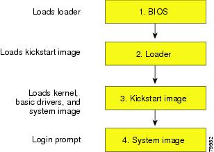
The regular switch boot goes through the following sequence (see Figure 5-3):
1.
2.
3.
4.
Figure 5-3 Regular Boot Sequence
If the images on your switch are corrupted and you are not able to proceed (error state), you can determine the reason and attempt to interrupt the switch boot sequence and recover the image by entering the BIOS configuration utility. Access this utility only when needed to recover a corrupted internal disk.
Caution
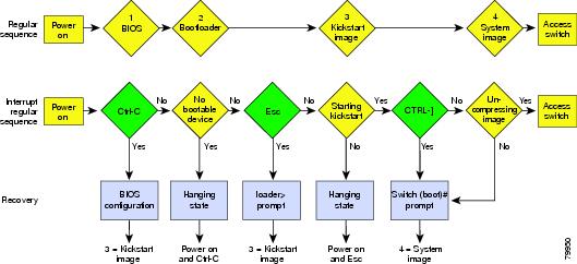
Recovery procedures require the regular sequence to be interrupted. The internal switch sequence goes through four phases between the time you turn the switch on and the time the switch prompt appears on your terminal—BIOS, boot loader, Kickstart, and system (see Table 5-1 and Figure 5-4).
Table 5-1 Recovery Interruption
BIOS
The BIOS begins the power-on self test, memory test, and other operating system applications. While the test is in progress, press Ctrl-C to enter the BIOS configuration utility and use the netboot option.
Boot loader
The boot loader uncompresses loaded software to boot an image using its file name as reference. These images are made available through bootflash. When the memory test is over, press Esc to enter the boot loader prompt.
Kickstart
When the boot loader phase is over, press Ctrl-] (Control key plus right bracket key) to enter the switch(boot)# prompt. If the corruption causes the console to stop at this prompt, copy the system image and reboot the switch.
System
The system image loads the configuration file of the last saved running configuration and returns a switch login prompt.
1 This prompt or message appears at the end of each phase.
2 This prompt or message appears when the switch cannot progress to the next phase.
Figure 5-4 Regular and Recovery Sequence
Recovery Using BIOS Setup
To recover a corrupted bootflash image (no bootable device found message) for a switch with a single supervisor module, follow these steps:
Step 1
Step 2
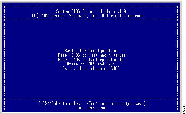
You see the netboot BIOS Setup Utility screen (see Figure 5-5).
Figure 5-5 BIOS Setup Utility
Note
Tab = Jump to next field
Ctrl-E = Down arrow
Ctrl-X = Up arrow
Ctrl-H = Erase (Backspace might not work if your terminal is not configured properly.)Step 3
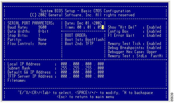
You see the BIOS setup CMOS Configuration screen (see Figure 5-6).
Figure 5-6 BIOS Setup Configuration (CMOS)
Step 4
Step 5
Step 6
Step 7
Step 8
Step 9
Step 10
Caution
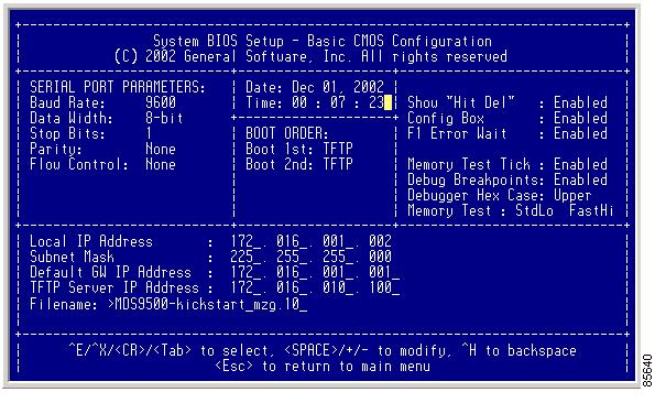
You see the configured changes (see Figure 5-7).
Figure 5-7 BIOS Setup Configuration (CMOS) Changes
Step 11
Step 12
Note
Caution
You are placed at the following prompt:
switch(boot)#Step 13
switch(boot)# init systemThe switch(boot)# prompt indicates that you have a usable kickstart image.
Step 14
Recovery from the loader> Prompt
To recover a corrupted kickstart image (system error state) for a switch with a single supervisor module, follow these steps:
Step 1
Note
00000589K Low Memory Passed
00000000K Ext Memory Passed
Hit ^C if you want to run SETUP....
Wait.....
If you wait too long, you will skip the boot loader phase and enter the kickstart phase.You see the loader> prompt.
Caution
Step 2
loader> ip address 172.16.1.2 255.255.255.0Found Intel EtherExpressPro100 82559ER at 0xe800, ROM address 0xc000Probing...[Intel EtherExpressPro100 82559ER]Ethernet addr: 00:05:30:00:52:27Address: 172.16.1.2Netmask: 255.255.255.0Server: 0.0.0.0Gateway: 0.0.0.0Step 3
loader> ip default-gateway 172.16.1.1Address: 172.16.1.2Netmask: 255.255.255.0Server: 0.0.0.0Gateway: 172.16.1.1Step 4
loader> boot tftp://172.16.10.100/kickstart-latestAddress: 172.16.1.2Netmask: 255.255.255.0Server: 172.16.10.100Gateway: 172.16.1.1Booting: /kick-282 console=ttyS0,9600n8nn quiet loader_ver="1.0(0.282)"................................................Image verification OKStarting kernel...INIT: version 2.78 bootingChecking all filesystems..... done.WARNING: image sync is going to be disabled after a loader netbootLoading system softwareINIT: Sending processes the TERM signalSending all processes the TERM signal... done.Sending all processes the KILL signal... done.Entering single-user mode...INIT: Going single userINIT: Sending processes the TERM signalswitch(boot)#The switch(boot)# prompt indicates that you have a usable Kickstart image.
Step 5
switch(boot)# copy tftp://172.16.10.100/system-img bootflash:system-imgTrying to connect to tftp server......switch(boot)# copy tftp://172.16.10.100/system-img bootflash:kickstart-imgTrying to connect to tftp server......Step 6
Recovery from the switch(boot)# Prompt
To recover a system image using the kickstart image for a switch with a single supervisor module, follow these steps:
Step 1
a.
switch(boot)# config tb.
switch(boot)(config)# interface mgmt0c.
switch(boot)(config-mgmt0)# ip address 172.16.1.2 255.255.255.0Step 2
switch(boot)(config-mgmt0)# no shutStep 3
a.
switch(boot)(config-mgmt0)# ip default-gateway 172.16.1.1Step 4
switch(boot)(config-mgmt0)# exitStep 5
switch(boot)(config)# exitStep 6
switch(boot)# copy tftp://172.16.10.100/system-img bootflash:system-imgTrying to connect to tftp server......Step 7
switch(boot)# copy tftp://172.16.10.100/system-img bootflash:kickstart-imgTrying to connect to tftp server......Step 8
switch(boot)# dir bootflash:total 100756drwxrwxrwx 2 admin 1024 Fri Sep 27 17:35:13 2002 .sshdrwxrwxrwx 2 admin 1024 Fri Sep 27 17:35:13 2002 .ssh2-rw-r--r-- 1 admin 13636096 Fri Sep 20 19:58:56 2002 kickstart-233b-rw-rw-rw- 1 admin 13636096 Wed Sep 25 17:26:47 2002 kickstart-233d-rw-rw-rw- 1 admin 14340096 Fri Sep 27 17:28:41 2002 kickstart-240-rw-r--r-- 1 admin 19280051 Fri Sep 20 20:02:33 2002 system-233b-rw-rw-rw- 1 admin 19281464 Wed Sep 25 17:28:12 2002 system-233d-rw-rw-rw- 1 admin 21917189 Fri Sep 27 17:29:51 2002 system-240drwxr-xr-x 2 admin 3072 Tue Oct 01 10:54:18 2002 logs-rwxr-xr-x 1 admin 636579 Mon Sep 30 05:32:42 2002 rdldrwxr-xr-x 2 admin 1024 Mon Sep 30 05:37:55 2002 src124688384 bytes total used311350272 bytes free459779072 bytes availableStep 9
switch(boot)# load bootflash:system-.imgUncompressing system image: bootflash:/system.imgCCCCCCCCCCCCCCCCCCCCCCCCCCCCCCCCCCCCCCCCCCCCCCCCCMDS SwitchWould you like to enter the initial configuration mode?(yes/no): yesSee the "Initial Setup Routine" section.
Note
Recovery for Switches with Dual Supervisor Modules
If one supervisor module is functioning and the other is not, boot the functioning supervisor module. Then use the booted supervisor module to bring up the supervisor module that is stuck. Issue the reload module slot force-dnld command (after you've logged into the switch) where slot is the slot number of the stuck supervisor module.
If both supervisor modules are not functioning, treat it like a single supervisor module recovery. First recover the image on one supervisor module and then follow the above process.
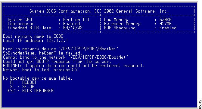
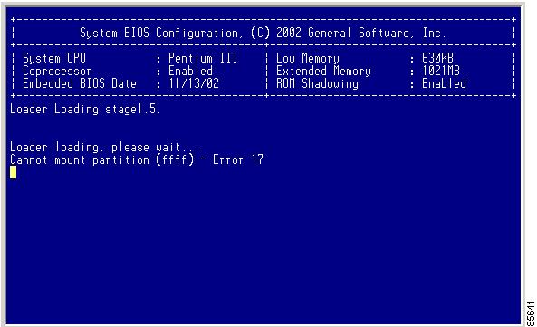
Recognizing Error States
If you see the error messages displayed in Figure 5-8 or Figure 5-9, follow the procedure specified in the "Recovery Using BIOS Setup" section.
Figure 5-8 Error State to Power On and Press the Ctrl-C
Figure 5-9 Error State to Power On and Press Esc
Upgrading a Boot Loader
The init bootloader command upgrades the boot loader nondisruptively.
Caution
To reload the boot loader on a switch, enter the boot boot_file_name command at the loader> prompt.
loader> boot bootfile1loading system software...........Programming Supervisor Module BIOS
You need to program the supervisor module BIOS only if a new BIOS image is provided by Cisco. You would then use the provided image to upgrade the BIOS. This command does not affect traffic and can be issued at any time.
Note
Caution
To validate, program, and verify the BIOS in a supervisor module, follow these steps:
Step 1
Step 2
switch# bios validate bootflash:MC0209.BINStep 3
switch# bios program bootflash:MC0209.BINStep 4
If the failure persists, it may be due to a hardware failure in the BIOS flash. In this case, the BIOS fails to boot up even if the card is rebooted.
Step 5
switch# bios verify
Note
Programming Switching Module BIOS
You need to program the switching module BIOS only if a new BIOS image is provided by Cisco. You would then use the provided image to upgrade the BIOS. This command does not affect traffic and can be issued at any time.
Note
Caution
To validate, program, and verify the BIOS in a switching module, follow these steps:
Step 1
Step 2
switch-180# cd bootflash:Step 3
switch-180# sh moduleMod Ports Module-Type Model Status--- ----- ------------------------------- ------------------ ------------3 32 1/2 Gbps FC Module DS-X9032 ok5 0 Supervisor/Fabric-1 DS-X9530-SF1-K9 active *6 0 Supervisor/Fabric-1 DS-X9530-SF1-K9 standby9 16 1/2 Gbps FC Module DS-X9016 okMod Sw Hw World-Wide-Name(s) (WWN)--- ----------- ------ --------------------------------------------------3 1.0(0.282) 0.0 20:81:00:05:30:00:13:9e to 20:a0:00:05:30:00:13:9e5 1.0(0.282) 0.602 --6 1.0(0.282) 0.0 --9 1.0(0.282) 0.0 22:01:00:05:30:00:13:9e to 22:10:00:05:30:00:13:9eMod MAC-Address(es) Serial-Num--- -------------------------------------- ----------3 00-05-30-00-18-62 to 00-05-30-00-18-665 00-05-30-00-84-1a to 00-05-30-00-84-1e jab063909cv6 00-05-30-00-2c-5e to 00-05-30-00-2c-629 00-05-30-00-03-0c to 00-05-30-00-03-10 123* this terminal sessionIn this example, the switching modules in Slot 3 and Slot 9 need to be upgraded.
Step 4
switch-180# attach module 3Attaching to module 3 ...To exit type 'exit', to abort type '$.'For more information on the attach module command, see the "Connecting to a Module" section.
Step 5
module-3# bios program bootflash:MC1113.BIN=============================================================================BIOS programming for -Input file (MC1113.BIN), size = 524288 bytes*****************************************************************************CAUTION !! Do NOT do ctrl-C or card reboot or hit any key till completion !!!*****************************************************************************Starting erase procedure ... wait####Erase successful for 524288 bytes ...Starting write procedure ... wait#########################################################################################Completed programming flash for 524288 bytes===============================================BIOS programming done in 173 sec===============================================Successful....NOTE !! You need to reboot the card for the BIOS to take effect !!module-3#Step 6
If the failure persists, it may be due to a hardware failure in the BIOS flash. In this case, the BIOS fails to boot up even if the card is rebooted.
Step 7
module-3# bios verifyVerification succeeded ...module-3#
Note
Default Factory Settings
Table 5-2 lists the default settings for all Cisco MDS 9000 Family switches.
Table 5-2 Default Factory Settings
auto-sync image option
Disabled
BOOT image specification
No image is specified