-
Cisco MDS 9000 Family Configuration Guide, Release 1.0(2a)
-
Index
-
Preface
-
Product Overview
-
Before You Begin
-
Initial Configuration
-
Configuring High Availability
-
Software Images
-
Managing Modules
-
Managing System Hardware
-
Configuring and Managing VSANs
-
Configuring Interfaces
-
Configuring Trunking
-
Configuring PortChannels
-
Configuring and Managing Zones
-
Managing FLOGI, Name Server, and RSCN Databases
-
Configuring System Security and AAA Services
-
Configuring Fibre Channel Routing Services and Protocols
-
Configuring IP Services
-
Configuring Call Home
-
Configuring Domain Parameters
-
Configuring Traffic Management
-
Configuring System Message Logging
-
Discovering SCSI Targets
-
Monitoring Network Traffic Using SPAN
-
Advanced Features and Concepts
-
Configuring Fabric Configuration Servers
-
Monitoring System Processes and Logs
-
 Feedback
Table Of Contents
Advanced Features and Concepts
About the Cisco Fabric Analyzer
Configuring the Cisco Fabric Analyzer
Sending Captures to Remote IP Addresses
Clearing Configured fcanalyzer Information
Viewing Display Filters Information
Configuring a Secondary MAC Address
Configuring the Switch for Interoperability
Cisco MDS 9500 Series Switches
Cisco MDS 9200 Series Switches
Verifying Interoperating Status
Cisco MDS 9500 Series Switches
Cisco MDS 9200 Series Switches
Advanced Features and Concepts
This chapter describes the advanced features provided in switches in the Cisco MDS 9000 Family. It includes the following sections:
•
Configuring a Fabric Analyzer
•
Configuring Time Out Values
The fctimer command modifies Fibre Channel protocol related timer values for the switch. You can only configure Fibre Channel time out values (TOVs) commands if all VSANs in a switch are suspended.
Note
You can use the fctimer command in configuration mode to configure the following TOVs:
•
•
•
Caution
If you issue the fctimer command without suspending all VSANs in a switch, you will get a warning message:
switch# fctimer D_S_TOV 6000Warning: This configuration would impact whole fabric.Since this configuration is not propagated to other switches.Please configure the same value in all the switchesIt is recommended that all vsans be suspended before executing this commandsuspend all vsans firstcould not update the valueswitch#Use the show fctimer command to display show the configured fctimer values (see Example 23-1).
Example 23-1 Displays Configured TOVs
switch# show fctimerF_S_TOV : 5000 millisecondsD_S_TOV : 5000 millisecondsE_D_TOV : 2000 millisecondsR_A_TOV : 10000 milliseconds
Note
Invoking fctrace
The fctrace feature allows you to:
•
•
You can invoke fctrace by providing the FC ID, the N port, or the NL port WWN of the destination. The frames are routed normally as long as they are forwarded through TE ports.
Once the frame reaches the edge of the fabric (the F port or FL port connected to the end node with the given port WWN or the FC ID), the frame is looped back (swapping the source ID and the destination ID) to the originator.
If the destination cannot be reached the path discovery starts, which traces the path up to the point of failure.
Note
To perform a fctrace operation, follow this step:
Note
Invoking fcping
The fcping feature verifies reachability of a node by checking its end-to-end connectivity. You can invoke the fcping feature by providing the FC ID or the destination port WWN information.
To perform a fcping operation, follow this step:
Configuring a Fabric Analyzer
Fibre Channel protocol analyzers capture, decode, and analyze frames and ordered sets on a link. While existing Fibre Channel analyzers can capture traffic at wire rate speed. They are expensive and support limited frame decoding. Also, to snoop traffic, the existing analyzers disrupt the traffic on the link while the analyzer is inserted into the link.
Cisco has brought protocol analysis within a storage network to a new capability level with the Cisco Fabric Analyzer. You can capture Fibre Channel control traffic from a switch and decode it without having to disrupt any connectivity, and without having to be local to the point of analysis.
Cisco's Fibre Channel protocol analyzer is based on two popular public-domain software applications:
•
•
Note
This section explains the following topics:
•
•
•
•
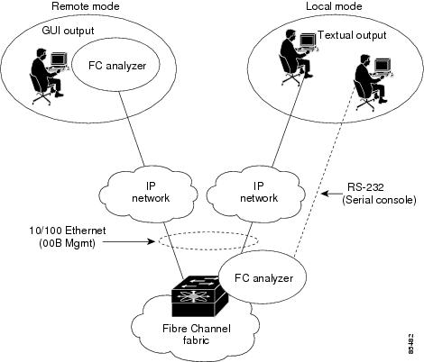
About the Cisco Fabric Analyzer
The Cisco Fabric Analyzer comprises two separate components (see Figure 23-1):
•
–
–
•
Figure 23-1 Cisco Fabric Analyzer Usage
Local Text-Based Capture
This component is a command-line driven text-based interface that captures traffic to and from the supervisor module in a Cisco MDS 9000 switch. It is a fully-functional decoder that is useful for quick debug purposes or for use when the remote capture daemon is not enabled. Additionally, because this tool is accessed from within the Cisco MDS 9000 switch, it is protected by the roles-based policy that limits access in each switch.
See the "Capturing Frames Locally" section.
Remote Capture Daemon
This daemon is the server end of the remote capture component. The Ethereal analyzer running on a host is the client end. They communicate with each other using the Remote Capture Protocol (RPCAP). RPCAP uses two end points, a TCP-based control connection and a TCP or UDP-based data connection based on TCP (default) or UDP. The control connection is used to remotely control the captures (start or stop the capture, or specify capture filters). Remote capture can only be performed to explicitly configured hosts. This technique prevents unauthorized machine in the network from snooping on the control traffic in the network.
RPCAP supports two setup connection modes based on fire wall restrictions.
•
•
Using capture filters, you can limit the amount of traffic that is actually sent to the client. Capture filters are specified at the client end—on Ethereal, not on the switch.
See the "Sending Captures to Remote IP Addresses" section.
GUI-Based Client
The Ethereal software runs on a host, such as a PC or workstation, and communicates with the remote capture daemon. This software is available in the public domain from http://www.ethereal.com. Since Ethereal has a GUI front-end, it supports a rich functionality such as colorized display, graphical assists in defining filters, and searching for specific frames. These features are documented on Ethereal's web site.
While remote capture via Ethereal supports capturing and decoding Fibre Channel frames from a Cisco MDS 9000 Family switch, the host running Ethereal does not require a Fibre Channel connection to the switch. The remote capture daemon running on the switch sends the captured frames over the out-of-band Ethernet management port. This capability allows you to capture and decode Fibre Channel frames from your desktop or laptop.
See the "Display Filters" section.
Configuring the Cisco Fabric Analyzer
You can configure the Cisco Fabric Analyzer by issuing the fcanalyzer local or fcanalyzer remote commands in configuration mode.
•
•
To use the Cisco Fabric Analyzer feature, traffic should be flowing to or from the supervisor module.
Capturing Frames Locally
Launches the textual version on the analyzer directly on the console screen. The capture can also be saved on the local file system.
To capture frames locally, follow these steps:
Sending Captures to Remote IP Addresses
Caution
To capture frames remotely, follow these steps:
To capture remote traffic, use one of the following options:
•
rpcap://<ipaddress or switch hostname>/eth2For example:
rpcap://cp-16/eth2rpcap://17.2.1.1/eth2•
ethereal -i rpcap://<ipaddress|hostname>[:<port>]/<interface>For example:
ethereal -i rpcap://172.22.1.1/eth2.or
ethereal -i rpcap://customer-switch.customer.com/eth2.Clearing Configured fcanalyzer Information
Use the clear fcanalyzer command to clear the entire list of configured hosts. Note that the existing connections are not terminated.
Viewing Display Filters Information
Use the show fcanalyzer command to display the list of hosts configured for a remote capture. See Example 23-2.
Example 23-2 Displays Configured Hosts
switch# show fcanalyzerPassiveClient = 10.21.0.3PassiveClient = 10.21.0.3ActiveClient = 10.21.0.3, DEFAULT
Note
Display Filters
You can selectively view captured frames by using the display filters feature. For example, instead of viewing all the frames from a capture, you may only want to view ELP request frames. This feature only limits the captured view—it does not affect the captured or the saved frames. Procedures to specify, use, and save display filters are already document in the Ethereal web site (http://www.ethereal.com). Some examples of how you can use this feature are provided below:
•
mdshdr.vsan == 2•
fcswils•
mdshdr.sof == SOFf•
swils.opcode == JLO || swils.opcode == LSU || swils.opcode == LSA•
fcels.opcode == FLOGI•
fcels.opcode == FLOGI && mdshdr.vsan == 2•
dNSDefining Display Filters
Display filters limit the frames that can be displayed, but not what is captured (similar to any view command). The filters to be displayed can be defined in multiple ways in the GUI application:
•
•
•
•
•
Regardless of the definition, each filter must be saved and identified with a name.
Note
Capture Filters
You can limit what frames are captures by using the capture filters feature in a remote capture. This feature limits the frames that are captured and sent from the remote switch to the host. For example, you can capture only class F frames. Capture filters is useful in restricting the amount of bandwidth consumed by the remote capture.
Unlike display filters, capture filters restricts a capture to the specified frames. No other frames will be visible until you specify a completely new capture.
The syntax for capture filter is different from the syntax for display filters. Capture filters use the Berkeley Packet Filter (BPF) library that is used in conjunction with the libpcap freeware. The list of all valid Fibre Channel capture filter fields are provided later in this section.
Procedures to configure capture filters are already document in the Ethereal web site (http://www.ethereal.com). Some examples of how you can use this feature are provided below:
•
vsan = 1•
class_f•
els•
dns•
fcp_cmd
Note
Permitted Capture Filters
o vsan
o src_port_idx
o dst_port_idx
o sof
o r_ctl
o d_id
o s_id
o type
o seq_id
o seq_cnt
o ox_id
o rx_id
o els
o swils
o fcp_cmd   (FCP Command frames only)
o fcp_data (FCP data frames only)
o fcp_rsp   (FCP response frames only)
o class_f
o bad_fc
o els_cmd
o swils_cmd
o fcp_lun
o fcp_task_mgmt
o fcp_scsi_cmd
o fcp_status
o gs_type      (Generic Services type)
o gs_subtype   (Generic Services subtype)
o gs_cmd
o gs_reason
o gs_reason_expl
o dns   (name server)
o udns (unzoned name server)
o fcs   (fabric configuration server)
o zs    (zone server)
o fc    (use as fc[x:y] where x is offset and y is length to compare)
o els   (use as els[x:y] similar to fc)
o swils (use as swils[x:y] similar to fc)
o fcp   (use as fcp[x:y] similar to fc)
o fcct (use as fcct[x:y] similar to fc)
Configuring World Wide Names
The world wide name (WWN) in the switch is equivalent to the Ethernet MAC address. As with the MAC address, you must uniquely associate the WWN to a single device. The principal switch selection and the allocation of domain IDs rely on the WWN. The WWN manager, a process-level manager residing on the switch's supervisor module, assigns WWNs to each switch. This WWN is independent of other WWNs on each switch. This centralized control of WWN has the following advantages:
•
•
Cisco MDS 9000 Family switches support three network address authority (NAA) address formats (see Table 23-1).
Caution
Configuring a Secondary MAC Address
To register the port ID objects, follow these steps:
Displaying WWN Information
Use the show wwn commands to display the status of the WWN configuration. See Examples 23-3 to 23-6.
Example 23-3 Displays the Status of All WWNs
switch# show wwn statusType 1 WWNs: Configured: 64 Available: 48 (75%) Resvd.: 16Types 2 & 5 WWNs: Configured: 524288 Available: 450560 (85%) Resvd.: 73728NKAU & NKCR WWN Blks: Configured: 1760 Available: 1760 (100%)Alarm Status: Type1: NONE Types 2&5: NONEExample 23-4 Displays Specified Block ID Information:
switch# show wwn status block-id 51WWNs in this block: 21:00:ac:16:5e:52:00:03 to 21:ff:ac:16:5e:52:00:03Num. of WWNs:: Configured: 256 Allocated: 0 Available: 256Block Allocation Status: FREEExample 23-5 Displays the WWN for a Specific Switch
switch# show wwn switchSwitch WWN is 20:00:ac:16:5e:52:00:00Example 23-6 Displays the WWN for a Specified VSAN
switch# show wwn vsan 1VSAN WWN of VSAN# 1 is 20:01:ac:16:5e:52:00:01Allocating Flat FC IDs
Based on Fibre Channel standards, one area is allocated to the N port attached to an F port in any switch. To save the number of FC IDs used, Cisco MDS 9000 Family switches provide a feature where each N ports can be assigned a single FC ID instead.
The three options to allocate FCID are auto (default), none, and flat.
To allocate flat FC IDs, follow these steps:
Caution
Enabling Loop Monitoring
When a disk is removed from a loop port, the loop stays active based on the bypass circuit. Thus the disk removal is not known until you try to communicate with the disk. To detect such removals, the disks can be polled periodically (every 20 seconds) using the fcinterop loop-monitor command. This command enables loop polling for FL ports in a Cisco MDS 9000 Family switch. By default, the fcinterop loop-monitor command is disabled.
To enable the loop monitoring feature, follow these steps:
Caution
Configuring the Switch for Interoperability
Interoperability enables multiple vendors' products come into contact with each other. Fibre Channel standards guide vendors towards common external Fibre Channel interfaces.
If all vendors followed the standards in the same manner, then interconnecting different products would become a trivial exercise. However, not all vendors follow the standards in the same way thus resulting in interoperability modes. This section briefly explains the basic concepts of these modes.
Each vendor has a regular mode and an equivalent interoperability mode, which specifically turns off advanced or proprietary features and provide the product with a more aimiable standards compliant implementation.
Table 23-2 lists the changes in switch behavior when you enable interoperability mode. These changes are specific to switches in the Cisco MDS 9000 Family while in interop mode.
Configuring Interoperability
The interop mode in Cisco MDS 9000 Family switches can be enabled disruptively or nondisruptively. The interoperability procedure is different in Cisco MDS 9500 Series and 9200 Series switches.
Note
Cisco MDS 9500 Series Switches
To configure interoperability in a Cisco MDS 9500 Series switch, follow these steps:
Step 1
switch# config tswitch(config)# vsan databaseswitch (config-vsan-db)# vsan 1 interopStep 2
Note
switch# config tswitch(config)# fcdomain domain 100 preferred vsan 1In Cisco MDS 9000 switches, the default is to request an ID from the principle switch. If the preferred option is used, Cisco MDS 9000 switches request a specific ID, but still join the fabric if the principle switch assigns a different ID. If the static option is used, the Cisco MDS 9000 switches does not join the fabric unless the principle switch agrees, and assigns the requested ID.
Note
Step 3
Note
switch# config tswitch(config)# fctimer e_d_tov ?<1000-100000> E_D_TOV in milliseconds(1000-100000)switch(config)# fctimer r_a_tov ?<5000-100000> R_A_TOV in milliseconds(5000-100000)Step 4
a.
switch(config)# fcdomain restart disruptive vsan 1or
b.
switch(config)# fcdomain restart vsan 1
Cisco MDS 9200 Series Switches
To configure interoperability in a Cisco MDS 9200 Series switch, follow these steps:
Step 1
switch# config tswitch(config)# vsan databaseswitch(config-vsan-db)# vsan 1 interopStep 2
Note
switch# config tswitch(config)# fcdomain domain 100 preferred vsan 1In Cisco MDS 9000 switches, the default is to request an ID from the principle switch. If the preferred option is used, Cisco MDS 9000 switches request a specific ID, but still join the fabric if the principle switch assigns a different ID. If the static option is used, the Cisco MDS 9000 switches does not join the fabric unless the principle switch agrees, and assigns the requested ID.
Note
Step 3
Note
switch# config tswitch(config)# fctimer e_d_tov ?<1000-100000> E_D_TOV in milliseconds(1000-100000)switch(config)# fctimer r_a_tov ?<5000-100000> R_A_TOV in milliseconds(5000-100000)Step 4
a.
switch(config)# fcdomain restart disruptive vsan 1or
b.
switch(config)# fcdomain restart vsan 1
Verifying Interoperating Status
This section highlights the commands used to verify if the fabric is up and running in interoperability mode.
Cisco MDS 9500 Series Switches
To verify the resulting status of issuing the interoperability command in a Cisco MDS 9500 Series switch, follow these steps:
Step 1
switch# show verCopyright (c) 2001-2005Cisco Systems, Inc.Softwarekickstart: version 1.0(2a) [gdb]System: version 1.0(2a) [gdb]HardwareRAM 1932864 kBbootflash: 503808 blocks (block size 512b)slot0: 0 blocks (block size 512b)Compile Time: 10/26/2002 2:00:00Step 2
switch# show int briefInterface Vsan Admin Admin Status Oper Oper Port-channelMode Trunk Mode SpeedMode (Gbps)--------------------------------------------------------------------fc2/1 1 auto on up E 2 --fc2/2 1 auto on up E 2 --fc2/3 1 auto on fcotAbsent -- -- --fc2/4 1 auto on down -- -- --fc2/5 1 auto on down -- -- --fc2/6 1 auto on down -- -- --fc2/7 1 auto on up E 1 --fc2/8 1 auto on fcotAbsent -- -- --fc2/9 1 auto on down -- -- --fc2/10 1 auto on down -- -- --Step 3
switch# show runBuilding Configuration...interface fc2/1no shutdowninterface fc2/2no shutdowninterface fc2/3interface fc2/4interface fc2/5interface fc2/6interface fc2/7no shutdowninterface fc2/8interface fc2/9interface fc2/10<snip>interface fc2/32interface mgmt0ip address 6.1.1.96 255.255.255.0switchport encap defaultno shutdownvsan databasevsan 1 interopboot system bootflash:/m9500-system-253e.bin sup-1boot kickstart bootflash:/m9500-kickstart-253e.bin sup-1boot system bootflash:/m9500-system-253e.bin sup-2boot kickstart bootflash:/m9500-kickstart-253e.bin sup-2callhomefcdomain domain 100 preferred vsan 1ip route 6.1.1.0 255.255.255.0 6.1.1.1ip routingline consoledatabits 5speed 110logging linecardssh key rsa 512 forcessh server enableswitchname MDS9509username admin password 5 $1$Li8/fBYX$SNc72.xt4nTXpSnR9OUFB/ role network-adminStep 4
switch# show vsan 1vsan 1 informationname:VSAN0001 stalactitesinteroperability mode:yes <-------------------- verify modeloadbalancing:src-id/dst-id/oxidoperational state:upStep 5
switch# show fcdomain vsan 1The local switch is a Subordinated Switch.Local switch run time information:State: StableLocal switch WWN: 20:01:00:05:30:00:51:1fRunning fabric name: 10:00:00:60:69:22:32:91Running priority: 128Current domain ID: 0x64(100) <---------------verify domain idLocal switch configuration information:State: EnabledAuto-reconfiguration: DisabledContiguous-allocation: DisabledConfigured fabric name: 41:6e:64:69:61:6d:6f:21Configured priority: 128Configured domain ID: 0x64(100) (preferred)Principal switch run time information:Running priority: 2Interface Role RCF-reject---------------- ------------- ------------fc2/1 Downstream Disabledfc2/2 Downstream Disabledfc2/7 Upstream Disabled---------------- ------------- ------------Step 6
switch# show fcdomain domain-list vsan 1Number of domains: 5Domain ID WWN--------- -----------------------0x61(97) 10:00:00:60:69:50:0c:fe0x62(98) 20:01:00:05:30:00:47:9f0x63(99) 10:00:00:60:69:c0:0c:1d0x64(100) 20:01:00:05:30:00:51:1f [Local]0x65(101) 10:00:00:60:69:22:32:91 [Principal]--------- -----------------------Step 7
switch# show fspf internal route vsan 1FSPF Unicast Routes---------------------------VSAN Number Dest Domain Route Cost Next hops-----------------------------------------------1 0x61(97) 500 fc2/21 0x62(98) 1000 fc2/1fc2/21 0x63(99) 500 fc2/11 0x65(101) 1000 fc2/7Step 8
switch# show fcns data vsan 1VSAN 1:------------------------------------------------------------------FCID TYPE PWWN (VENDOR) FC4-TYPE:FEATURE------------------------------------------------------------------0x610400 N 10:00:00:00:c9:24:3d:90 (Emulex) scsi-fcp0x6105dc NL 21:00:00:20:37:28:31:6d (Seagate) scsi-fcp0x6105e0 NL 21:00:00:20:37:28:24:7b (Seagate) scsi-fcp0x6105e1 NL 21:00:00:20:37:28:22:ea (Seagate) scsi-fcp0x6105e2 NL 21:00:00:20:37:28:2e:65 (Seagate) scsi-fcp0x6105e4 NL 21:00:00:20:37:28:26:0d (Seagate) scsi-fcp0x630400 N 10:00:00:00:c9:24:3f:75 (Emulex) scsi-fcp0x630500 N 50:06:01:60:88:02:90:cb scsi-fcp0x6514e2 NL 21:00:00:20:37:a7:ca:b7 (Seagate) scsi-fcp0x6514e4 NL 21:00:00:20:37:a7:c7:e0 (Seagate) scsi-fcp0x6514e8 NL 21:00:00:20:37:a7:c7:df (Seagate) scsi-fcp0x651500 N 10:00:00:e0:69:f0:43:9f (JNI)Total number of entries = 12
Note
Cisco MDS 9200 Series Switches
To verify the resulting status of issuing the interoperability command in a Cisco MDS 9200 Series switch, follow these steps:
Step 1
switch# show verCopyright (c) 2001-2005Cisco Systems, Inc.Softwarekickstart: version 1.0(2a) [gdb]System: version 1.0(2a) [gdb]HardwareRAM 963116 kBbootflash: 503808 blocks (block size 512b)slot0: 0 blocks (block size 512b)Compile Time: 10/26/2002 2:00:00Step 2
switch# show int brief------------------------------------------------------------------Interface Vsan Admin Admin Status Oper Oper Port-channelMode Trunk Mode SpeedMode (Gbps)------------------------------------------------------------------fc1/1 1 auto on up E 2 --fc1/2 1 auto on fcotAbsent -- -- --fc1/3 1 auto on up E 2 --fc1/4 1 auto on down -- -- --fc1/5 1 auto on down -- -- --fc1/6 1 auto on up E 1 --fc1/7 1 auto on fcotAbsent -- -- --fc1/8 1 auto on fcotAbsent -- -- --fc1/9 1 auto on down -- -- --Step 3
switch# show runBuilding Configuration...interface fc1/1no shutdowninterface fc1/2interface fc1/3switchport speed 2000no shutdowninterface fc1/4interface fc1/5interface fc1/6switchport speed 1000no shutdowninterface fc1/7interface fc1/8interface fc1/9...interface mgmt0ip address 6.1.1.95 255.255.255.0no shutdownvsan databasevsan 1 interopboot system bootflash:/m9200-system-253e.binboot kickstart bootflash:/m9200-kickstart-253e.bincallhomefcdomain domain 98 preferred vsan 1line consoledatabits 5speed 110logging linecardswitchname MDS9216username admin password 5 MF7UQdWLEqUFE role network-adminStep 4
switch# show vsan 1vsan 1 informationname:VSAN0001 state:activeinteroperability mode:yes <--------------------- verify interoperabilityloadbalancing:src-id/dst-id/oxidoperational state:upStep 5
switch# show fcdomain vsan 1The local switch is a Subordinated Switch.Local switch run time information:State: StableLocal switch WWN: 20:01:00:05:30:00:47:9fRunning fabric name: 10:00:00:60:69:22:32:91Running priority: 128Current domain ID: 0x62(98) <-----------------------verify domain IDLocal switch configuration information:State: EnabledAuto-reconfiguration: DisabledContiguous-allocation: DisabledConfigured fabric name: 41:6e:64:69:61:6d:6f:21Configured priority: 128Configured domain ID: 0x62(98) (preferred)Principal switch run time information:Running priority: 2Interface Role RCF-reject---------------- ------------- ------------fc1/1 Upstream Disabledfc1/3 Non-principal Disabledfc1/6 Non-principal Disabled---------------- ------------- ------------Step 6
switch# show fcdomain domain-list vsan 1Number of domains: 5Domain ID WWN--------- -----------------------0x61(97) 10:00:00:60:69:50:0c:fe0x62(98) 20:01:00:05:30:00:47:9f [Local]0x63(99) 10:00:00:60:69:c0:0c:1d0x64(100) 20:01:00:05:30:00:51:1f0x65(101) 10:00:00:60:69:22:32:91 [Principal]--------- -----------------------Step 7
switch# show fspf internal route vsan 1FSPF Unicast Routes---------------------------VSAN Number Dest Domain Route Cost Next hops-----------------------------------------------1 0x61(97) 500 fc1/11 0x63(99) 500 fc1/31 0x64(100) 1000 fc1/1fc1/31 0x65(101) 1000 fc1/6Step 8
switch# show fcns data vsan 1VSAN 1:------------------------------------------------------------------FCID TYPE PWWN (VENDOR) FC4-TYPE:FEATURE------------------------------------------------------------------0x610400 N 10:00:00:00:c9:24:3d:90 (Emulex) scsi-fcp0x6105dc NL 21:00:00:20:37:28:31:6d (Seagate) scsi-fcp0x6105e0 NL 21:00:00:20:37:28:24:7b (Seagate) scsi-fcp0x6105e1 NL 21:00:00:20:37:28:22:ea (Seagate) scsi-fcp0x6105e2 NL 21:00:00:20:37:28:2e:65 (Seagate) scsi-fcp0x6105e4 NL 21:00:00:20:37:28:26:0d (Seagate) scsi-fcp0x630400 N 10:00:00:00:c9:24:3f:75 (Emulex) scsi-fcp0x630500 N 50:06:01:60:88:02:90:cb scsi-fcp0x6514e2 NL 21:00:00:20:37:a7:ca:b7 (Seagate) scsi-fcp0x6514e4 NL 21:00:00:20:37:a7:c7:e0 (Seagate) scsi-fcp0x6514e8 NL 21:00:00:20:37:a7:c7:df (Seagate) scsi-fcp0x651500 N 10:00:00:e0:69:f0:43:9f (JNI)Total number of entries = 12