-
Cisco MDS 9000 Family Switch-to-Switch Interoperability Configuration Guide
-
Index
-
Preface
-
Interoperability Overview
-
Interoperability Limitations
-
MDS 9000 Core with Brocade Edge Topology (Interop Mode 1)
-
MDS 9000 Core with Brocade and McData Edge Topology (Interop Mode 1)
-
MDS 9000 Switch and McData Dual Core Topology (Interop Mode 1)
-
MDS 9000 Core with Brocade 3900/12000 Edge Toplogy
-
MDS 9000 Legacy Switch Interop Mode 2
-
MDS 9000 Legacy Switch Interop Mode 3
-
MDS 9000 Legacy Switch Interop Mode 4
-
MDS 9020 Switch Interoperability
-
Interoperability with Inter-VSAN Routing
-
IBM BladeCenter
-
Standards Perspectives
-
Caveats
-
 Feedback
Table Of Contents
MDS 9000 Legacy Switch Interop Mode 2
Management Server Platform Database
Configuring the MDS 9000 Switch
Configuring the Brocade Switch
Verifying the MDS 9000 Switch Settings
Verifying the Brocade 3800 Switch Settings
Using the Brocade WebTools GUI
Using the Cisco Fabric Manager GUI
Using the Cisco MDS SAN-OS CLI
Verifying Zone Set and Configuration Activation
MDS 9000 Legacy Switch Interop Mode 2
This chapter describes how to set up a basic interop mode 2 topology, with two MDS 9000 switches and two Brocade switches in a serial topology.
This chapter includes the following sections:
Specifications
With standard interop mode 1, interoperability between the MDS 9000 switch and the Brocade switches requires an outage in the Brocade fabric, because the Brocade switch must be reconfigured into interoperability mode. MDS SAN-OS Release 1.2 introduced a new interoperability mode that does not require the Brocade switch to be reconfigured from its native operational mode.
MDS SAN-OS Release 1.2 supports three modes of operation for interoperability:
•
Default or Native Mode—This is the default mode or behavior for a VSAN communicating between a SAN composed entirely of MDS 9000 switches.
•
•
The following are key characteristics of legacy switch interop mode:
•
•
•
•
•
•
•
•
The following switches and code levels were used for this example configuration:
•
•
•
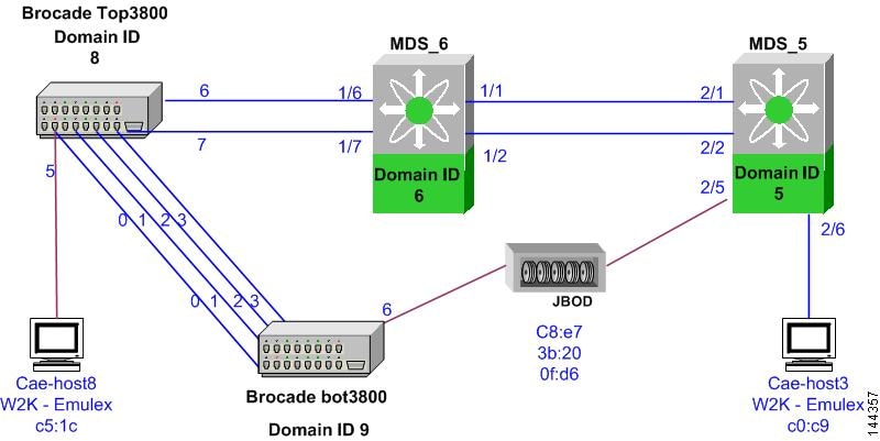
Figure 7-1 shows the topology used for this example configuration.
Figure 7-1 MDS 9000 Switch Legacy Switch Interop Topology
Expected Topology Behavior
This section covers switch-specific features and identifies features that cannot be used or that behave differently in this topology (Figure 7-1) as compared to a homogeneous MDS 9000 switch or Brocade fabric.
This section contains the following topics:
•
Zoning
An MDS 9000 switch configured for legacy switch interop mode can be attached without any detrimental effect on the Brocade fabric. When an MDS VSAN in legacy switch mode is connected to a Brocade fabric, the rules for zoning depend on where the device being zoned is located.
For devices attached to an MDS 9000 switch, zoning must be done by pWWN. For devices attached to Brocade switches, zoning can be done either by pWWN or domain/port (a Brocade native mode zoning format). Domain/port zoning cannot be used for MDS-attached hosts because the Brocade switches do not understand the MDS 9000 switch fWWN interface nomenclature. Brocade switches use a proprietary zone set activation sequence that does not follow the FC-SW3 standard. The sequence is:
1.
2.
3.
4.
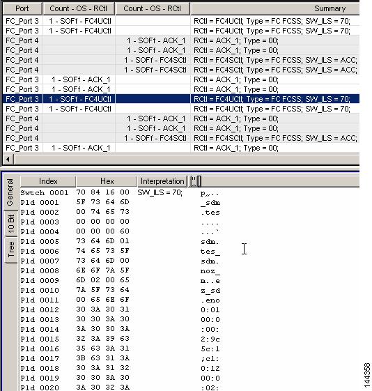
When a zone set (configuration, in Brocade terminology) is activated by the Brocade switch, proprietary frames are sent and acknowledged by all switches including MDS 9000 switches. The Brocade proprietary-zone frames appear as two 0x70 frames on a Fibre Channel analyzer or the MDS 9000 switch internal FC analyzer.
Zone set and zone names cannot use the "$" or "-" symbols.
The zone merge process has stronger restrictions in this mode. The following additional restrictions apply:
•
•
Note
Figure 7-2 Brocade Proprietary Zoning Frames
Note
ISL Flow Control
Brocade uses a proprietary flow control called Virtual Channel (VC) flow control. VC flow control is used by Brocade for fair traffic distribution during congested fabrics by prioritizing management traffic.
When an ISL between an MDS 9000 switch and Brocade switch comes up, the ISL negotiates for the standards-based buffer-to-buffer flow control during ELP. The MDS 9000 switch rejects the Brocade proprietary VC flow control and responds with the standards-based buffer-to-buffer flow control.
To enable Brocade to accept the standards-based flow control on Brocade firmware versions 3.1.0 and 4.1.1 so that the ISL will complete negotiation, use the portcfgislmode slot/port 1 command on the Brocade switch. Switches running version 2.x firmware do not require this command.
This does not affect any other ISLs in the fabric. All Brocade-to-Brocade ISLs can still be native VC flow control and MDS 9000 switch-to-MDS 9000 switch ISLs can still be TE (trunking or multi-VSAN) ISLs. Having a Brocade-to-MDS 9000 switch ISL using buffer-to-buffer flow control should have no noticeable impact to the fabric.
Trunking and PortChannels
Brocade's trunking feature is comparable to MDS 9000 switch PortChannels. Trunking is not supported between MDS 9000 switches and Brocade switches. Trunking between two Brocade switches is supported when adding an MDS 9000 switch in legacy switch interop mode 2 to a Brocade fabric. PortChannels between two MDS 9000 switches are also supported.
Domain IDs
There is no limitation to the domain ID range when the MDS 9000 switch is operating in legacy switch interop mode 2. When an MDS 9000 switch in legacy switch interop mode 2 joins a Brocade fabric, there is no disruption to domain assignment and the complete domain ID range is available to all switches in the fabric. In the default interoperability mode (mode 1), Brocade switches and MDS 9000 switches require domain IDs in the 97 to 127 range.
Quickloop
Brocade's Quickloop feature can only be used between two Brocade switches. The MDS 9000 switch cannot participate in the quickloop. However, the MDS 9000 switch can join a fabric that has quickloop configured between Brocade switches.
Management Server Platform Database
This Brocade feature does not have to be disabled. An MDS 9000 switch responds as Management Server Platform capable. In comparison, standard interop mode 1 requires this Brocade feature to be disabled.
Configuration
This section describes how to set up a simple fabric consisting of Brocade switches running in native mode and MDS 9000 switches with a VSAN configured for legacy switch interop mode 2. (See Figure 7-1.)
This section includes the following topics:
•
•
Before You Begin
Check for the proper MDS SAN-OS and Brocade firmware version levels.
Step 1
MDS_5# show versionCisco Storage Area Networking Operating System (SAN-OS) SoftwareTAC support: http://www.cisco.com/tacCopyright (c) 2002-2003 by Cisco Systems, Inc. All rights reserved.The copyright for certain works contained herein are owned byAndiamo Systems, Inc. and/or other third parties and are used anddistributed under license.SoftwareBIOS: version 1.0.7loader: version 1.0(3a)kickstart: version 1.2(1) [build 1.2(0.96a)]system: version 1.2(1) [build 1.2(0.96a)]BIOS compile time: 03/20/03kickstart image file is: bootflash:/k96akickstart compile time: 7/29/2003 0:00:00system image file is: bootflash:/s96asystem compile time: 7/29/2003 0:00:00HardwareRAM 1027584 kBbootflash: 500736 blocks (block size 512b)slot0: 0 blocks (block size 512b)MDS_5 uptime is 0 days 20 hours 59 minute(s) 50 second(s)Last reset at 840233 usecs after Mon Aug 11 15:52:48 2003Reason: Reset Requested by CLI command reloadSystem version: 1.2(1)Step 2
Top3800:admin> versionKernel: 5.3.1Fabric OS: v3.0.2kMade on: Fri Nov 15 10:46:10 PST 2002Flash: Fri Nov 15 10:47:31 PST 2002BootProm: Tue Oct 30 10:24:38 PST 2001
Configuring the MDS 9000 Switch
To configure the MDS 9000 switch, follow these steps:
Step 1
MDS_5# config tMDS_5 (config)# vsan databaseMDS_5 (config-vsan-db)# vsan 113 interop 2MDS_6# config tMDS_6 (config)# vsan databaseMDS_6 (config-vsan-db)# vsan 113 interop 2Step 2
MDS_5 (config-vsan-db)# vsan 113 interface 2/6 Host1MDS_5 (config-vsan-db)# vsan 113 interface 2/5 JBODMDS_5 (config-vsan-db)# vsan 113 interface 2/1 ISL to MDS_6MDS_5 (config-vsan-db)# vsan 113 interface 2/2 ISL to MDS_6MDS_6 (config-vsan-db)# vsan 113 interface 1/1 ISL to MDS_5MDS_6 (config-vsan-db)# vsan 113 interface 1/2 ISL to MDS_5MDS_6 (config-vsan-db)# vsan 113 interface 2/1 ISL to Top3800MDS_6 (config-vsan-db)# vsan 113 interface 2/2 ISL to Top3800Step 3
MDS_6(config)# interface fc 1/6-7MDS_6(config-if)# switchport fcrxbbcredit 16MDS_6(config-if)# no shut
Note
Configuring the Brocade Switch
Now that the MDS 9000 switch is configured, there will be no configuration or disruption to the Brocade fabric. All that is required is to enable the new ISL ports.
Top3800:admin> portcfgislmode 6 1   <== required for 2400/2800/3200/3800 code 3.1.0 higher
and 12000/3900 code 4.1.1 or higher
Top3800:admin> portcfgislmode 7,1Top3800:admin> portenable 6Top3800:admin> portenable 7Verification
This section highlights the commands used to verify that the fabric is up and running in legacy switch interop mode 2. The output is based on the example topology shown in Figure 7-1.
This section includes the following topics:
•
•
Verifying the MDS 9000 Switch Settings
The following examples show the commands used to verify the MDS 9000 switch settings.
MDS_6# show runBuilding Configuration ...vsan databasevsan 100 name Rob_mdsvsan 113 name Rob_interop interop 2 <==== interop mode 2 VSANMDS_6# show vsan 113vsan 113 informationname:Rob_native state:activeinteroperability mode:2 <==== Legacy Switch Interoploadbalancing:src-id/dst-id/oxidoperational state:upMDS_6# show fcdomain domain-list vsan 113Number of domains: 4Domain ID WWN--------- -----------------------0x05(5) 20:71:00:05:30:00:87:9f [Principal] <==== MDS_50x06(6) 20:71:00:0b:46:79:f2:41 [Local] <==== MDS_60x08(8) 10:00:00:60:69:51:29:71 <==== Top_38000x09(9) 10:00:00:60:69:51:3a:60 <==== Bot_3800MDS_6# show fspf internal route vsan 113FSPF Unicast Routes---------------------------VSAN Number Dest Domain Route Cost Next hops-----------------------------------------------113 0x05(5) 250 port-channel 1113 0x08(8) 500 fc1/6fc1/7113 0x09(9) 1000 fc1/6fc1/7MDS_6# show fcns database vsan 113VSAN 113:--------------------------------------------------------------------------FCID TYPE PWWN (VENDOR) FC4-TYPE:FEATURE--------------------------------------------------------------------------0x050001 N 10:00:00:05:30:00:87:a3 (Cisco) ipfc0x050002 N 10:00:00:00:c9:30:c0:c9 (Emulex) scsi-fcp0x0501ca NL 22:00:00:20:37:5a:7f:5a (Seagate) scsi-fcp0x0501cc NL 22:00:00:20:37:60:9c:ae (Seagate) scsi-fcp0x0501cd NL 22:00:00:20:37:6e:fc:97 (Seagate) scsi-fcp0x0501ce NL 22:00:00:20:37:46:0f:d6 (Seagate) scsi-fcp0x0501d1 NL 22:00:00:20:37:5b:c8:e7 (Seagate) scsi-fcp0x0501d3 NL 22:00:00:20:37:5a:63:06 (Seagate) scsi-fcp0x0501d5 NL 22:00:00:20:37:73:3b:20 (Seagate) scsi-fcp0x060001 N 10:00:00:0b:46:79:f2:45 (Cisco) ipfc0x081500 N 10:00:00:00:c9:21:c5:1c (Emulex) scsi-fcp0x0916ca NL 21:00:00:20:37:5a:7f:5a (Seagate) scsi-fcp0x0916cc NL 21:00:00:20:37:60:9c:ae (Seagate) scsi-fcp0x0916cd NL 21:00:00:20:37:6e:fc:97 (Seagate) scsi-fcp0x0916ce NL 21:00:00:20:37:46:0f:d6 (Seagate) scsi-fcp0x0916d1 NL 21:00:00:20:37:5b:c8:e7 (Seagate) scsi-fcp0x0916d3 NL 21:00:00:20:37:5a:63:06 (Seagate) scsi-fcp0x0916d5 NL 21:00:00:20:37:73:3b:20 (Seagate) scsi-fcpTotal number of entries = 18
Note
Verifying the Brocade 3800 Switch Settings
The following examples show the commands used to verify the Brocade 3800 switch settings.
Bot3800:admin> msPlCapabilityShowPlatformSwitch WWN Service Capable Capability Name======================== =============== ========== =======20:71:00:05:30:00:87:9f Yes 0x00000007 "MDS_5"20:71:00:0b:46:79:f2:41 Yes 0x00000007 "MDS_6"10:00:00:60:69:51:29:71 Yes 0x0000008f "Top3800"10:00:00:60:69:51:3a:60 Yes 0x0000008f "Bot3800"Capability Bit Definitions:Bit 0: Basic Configuration Service Supported.Bit 1: Platform Management Service Supported.Bit 2: Topology Discovery Service Supported.Bit 3: Unzoned Name Server Service Supported.Bit 4: M.S. Fabric Zone Service Supported.Bit 5: Fabric Lock Service Supported.Bit 6: Timer Service Supported.Bit 7: RSCN Small Payload Supported.Others: Reserved.Bot3800:admin> licenseshowSzSebezc9RT0TfcA:Web licenseZoning licenseFabric licenseTop3800:admin> switchshowswitchName: Top3800switchType: 9.2switchState: OnlineswitchMode: Native Native Brocade ModeswitchRole: SubordinateswitchDomain: 8switchId: fffc08switchWwn: 10:00:00:60:69:51:29:71switchBeacon: OFFZoning: ON (native_zoneset)port 0: id N2 Online E-Port 10:00:00:60:69:51:3a:60 "Bot3800" (downstream)port 1: id N2 Online E-Port 10:00:00:60:69:51:3a:60 "Bot3800"port 2: id N2 Online E-Port 10:00:00:60:69:51:3a:60 "Bot3800"port 3: id N2 Online E-Port 10:00:00:60:69:51:3a:60 "Bot3800"port 4: -- N2 No_Moduleport 5: id N1 Online F-Port 10:00:00:00:c9:21:c5:1cport 6: id N2 Online E-Port 20:00:00:0b:46:79:f2:40port 7: id N2 Online E-Port 20:00:00:0b:46:79:f2:40 (upstream)port 8: -- N2 No_Moduleport 9: -- N2 No_Moduleport 10: -- N2 No_Moduleport 11: -- N2 No_Moduleport 12: -- N2 No_Moduleport 13: -- N2 No_Moduleport 14: -- N2 No_Moduleport 15: -- N2 No_ModuleBot3800:admin> switchshowswitchName: Bot3800switchType: 9.2switchState: OnlineswitchMode: NativeswitchRole: SubordinateswitchDomain: 9switchId: fffc09switchWwn: 10:00:00:60:69:51:3a:60switchBeacon: OFFZoning: ON (native_zoneset)port 0: id N2 Online E-Port 10:00:00:60:69:51:29:71 "Top3800" (upstream)port 1: id N2 Online E-Port 10:00:00:60:69:51:29:71 "Top3800"port 2: id N2 Online E-Port 10:00:00:60:69:51:29:71 "Top3800"port 3: id N2 Online E-Port 10:00:00:60:69:51:29:71 "Top3800"port 4: -- N2 No_Moduleport 5: -- N2 No_Moduleport 6: id N1 Online L-Port 7 publicport 7: id N2 No_Lightport 8: -- N2 No_Moduleport 9: -- N2 No_Moduleport 10: -- N2 No_Moduleport 11: -- N2 No_Moduleport 12: -- N2 No_Moduleport 13: -- N2 No_Moduleport 14: -- N2 No_Moduleport 15: -- N2 No_Module
Note
Bot3800:admin> topologyshow4 domains in the fabric; Local Domain ID: 9Domain Metric Hops Out Port In Ports Flags Bandwidth Name-----------------------------------------------------------------------5 1250 3 0 0x00000040 D 2 (Gbs) "MDS_5"1 0x00000000 D 2 (Gbs)2 0x00000000 D 2 (Gbs)3 0x00000000 D 2 (Gbs)Type <CR> to continue, Q<CR> to stop:6 1000 2 0 0x00000040 D 2 (Gbs) "MDS_6"1 0x00000000 D 2 (Gbs)2 0x00000000 D 2 (Gbs)3 0x00000000 D 2 (Gbs)Type <CR> to continue, Q<CR> to stop:8 500 1 1 0x00000040 D 2 (Gbs) "Top3800"0 0x00000000 D 2 (Gbs)2 0x00000000 D 2 (Gbs)3 0x00000000 D 2 (Gbs)Type <CR> to continue, Q<CR> to stop:Bot3800:admin> interopmodeinteropMode is 0
Note
Top3800:admin> portshow 6portFlags: 0x28057 portLbMod: 0x0 PRESENT ACTIVE E_PORT G_PORT U_PORT LOGIN LEDportType: 4.1portState: 1 OnlineportPhys: 6 In_SyncportScn: 5 E_Port Flow control mode 2 <==== B2B Standards Flow ControlportRegs: 0x81060000portData: 0x10282a20portId: 081600portWwn: 20:06:00:60:69:51:29:71portWwn of device(s) connected: 20:06:00:0b:46:79:f2:40Distance: normalSpeed: N2GbpsInterrupts: 62094 Link_failure: 0 Frjt: 0Unknown: 72 Loss_of_sync: 28 Fbsy: 0Lli: 133 Loss_of_sig: 7Proc_rqrd: 61928 Protocol_err: 0Timed_out: 0 Invalid_word: 0Rx_flushed: 0 Invalid_crc: 0Tx_unavail: 0 Delim_err: 0Free_buffer: 0 Address_err: 5Overrun: 0 Lr_in: 7Suspended: 0 Lr_out: 14Parity_err: 0 Ols_in: 7Ols_out: 0Top3800:admin> portshow 1portFlags: 0x28057 portLbMod: 0x0 PRESENT ACTIVE E_PORT G_PORT U_PORT LOGIN LEDportType: 4.1portState: 1 OnlineportPhys: 6 In_SyncportScn: 5 E_Port <==== VC Flow Control to Brocade 3800BotportRegs: 0x81010000portData: 0x101f70c0portId: 081100portWwn: 20:01:00:60:69:51:29:71portWwn of device(s) connected: 20:01:00:60:69:51:3a:60Distance: normalSpeed: N2GbpsInterrupts: 181162 Link_failure: 1 Frjt: 0Unknown: 23 Loss_of_sync: 2 Fbsy: 0Lli: 23 Loss_of_sig: 1Proc_rqrd: 181119 Protocol_err: 0Timed_out: 0 Invalid_word: 0Rx_flushed: 0 Invalid_crc: 0Tx_unavail: 0 Delim_err: 0Free_buffer: 0 Address_err: 0Overrun: 0 Lr_in: 5Suspended: 0 Lr_out: 1Parity_err: 0 Ols_in: 1Ols_out: 4Bot3800:admin> nsallshow{050001 050002 0501ca 0501cc 0501cd 0501ce 0501d1 0501d30501d5 060001 081500 0916ca 0916cc 0916cd 0916ce 0916d10916d3 0916d518 Nx_Ports in the Fabric }
Note
Bot3800:admin> urouteshowLocal Domain ID: 9In Port Domain Out Port Metric Hops Flags Next (Dom, Port)----------------------------------------------------------------------------6 5 0 1250 3 D 8,06 0 1000 2 D 8,08 1 500 1 D 8,1Bot3800:admin> configshowEthernet addresses: 0:60:69:51:3a:60Nvram datadata: fei(0,0)host:/usr/switch/firmware e=172.22.36.137:fffffe00 g=172.22.36.1 u=user tn=Bot3800Type <CR> to continue, Q<CR> to stop:diag.postDisable: 0fabric.domain: 9fabric.ops.BBCredit: 16fabric.ops.E_D_TOV: 2000fabric.ops.R_A_TOV: 10000fabric.ops.dataFieldSize: 2112fabric.ops.max_hops: 7fabric.ops.mode.SeqSwitching: 0fabric.ops.mode.fcpProbeDisable: 0fabric.ops.mode.isolate: 0fabric.ops.mode.longDistance: 0fabric.ops.mode.noClassF: 0fabric.ops.mode.pidFormat: 0When operating with legacy switch interop mode 2 VSANs, verify that the core PID format is 0. If the Brocade fabric has switches with more than 16 ports (such as Brocade models 3900 and 12000), the core PID will be set to 1. On earlier switches with fewer than 16 ports, Brocade initially allocated one nibble of the FC ID / PID in area field 0x0 - F for the port number. This limited the port count to 16.
When the core PID is set to 1, the allocated bytes in the FC ID/PID allow the use of port numbers 0x00 - FF.
•
•
Zoning
In this example, zones, zone sets, and configurations, FCalias and aliases are created and activated from the following management platforms:
•
•
•
•
After the zone set is activated, commands are issued to verify that the MDS 9000 switch and the Brocade switches properly learn the alias, zones, and zone sets. In Brocade terminology, the zone set is known as the configuration. The active zone set in the MDS 9000 switch is known as the effective configuration on the Brocade switches.
In the following examples, the same alias, zones, and zone sets are created using each management platform. This provides a direct comparison between the various tools. Because the show command output would not vary based on the management platform used to create the zoning information, the show commands used to verify the zone configuration are shown once at the end of each section.
When creating zones, you can only use pWWNs for MDS 9000 switch attached nodes, and either pWWN or domain/port for Brocade attached nodes. Aliases can also be used by either switch, but the alias of devices attached to the MDS 9000 switch must be by pWWN only. Aliases for devices attached to Brocade switches can be either pWWN or domain/port.
The following zone configuration will be created on each of the management platforms. This configuration relates to the topology shown in Figure 7-1.
One alias (a3800top_port5_pwwn) with two members
•
•
Two zones
•
–
–
•
–
–
One zone set (native_zoneset) with two zones assigned
•
•
Using the Brocade WebTools GUI
To use the Brocade WebTools GUI for zoning, follow these steps:
Step 1
Step 2
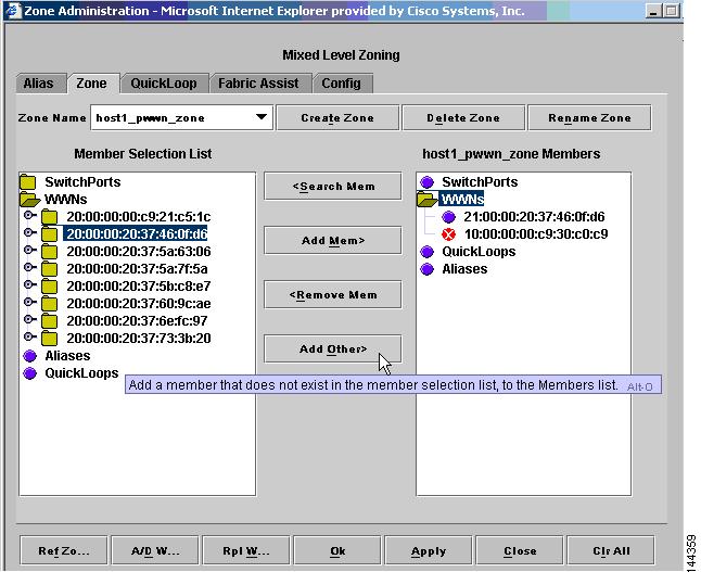
Figure 7-3 Brocade WebTools Zone Administration
Step 3
Step 4
Note
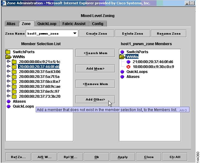
Figure 7-4 Brocade WebTools Zone Administration, Add Other
Step 5
MDS_6# show fcns database v 113VSAN 113:--------------------------------------------------------------------------FCID TYPE PWWN (VENDOR) FC4-TYPE:FEATURE--------------------------------------------------------------------------0x050000 N 10:00:00:00:c9:30:c0:c9 (Emulex) scsi-fcp0x050003 N 10:00:00:05:30:00:87:a3 (Cisco) ipfc0x0501ca NL 22:00:00:20:37:5a:7f:5a (Seagate) scsi-fcp0x0501cc NL 22:00:00:20:37:60:9c:ae (Seagate) scsi-fcp0x0501cd NL 22:00:00:20:37:6e:fc:97 (Seagate) scsi-fcp0x0501ce NL 22:00:00:20:37:46:0f:d6 (Seagate) scsi-fcp0x0501d1 NL 22:00:00:20:37:5b:c8:e7 (Seagate) scsi-fcp0x0501d3 NL 22:00:00:20:37:5a:63:06 (Seagate) scsi-fcp0x0501d5 NL 22:00:00:20:37:73:3b:20 (Seagate) scsi-fcp0x060002 N 10:00:00:0b:46:79:f2:45 (Cisco) ipfc0x081500 N 10:00:00:00:c9:21:c5:1c (Emulex) scsi-fcp0x0916ca NL 21:00:00:20:37:5a:7f:5a (Seagate) scsi-fcp0x0916cc NL 21:00:00:20:37:60:9c:ae (Seagate) scsi-fcp0x0916cd NL 21:00:00:20:37:6e:fc:97 (Seagate) scsi-fcp0x0916ce NL 21:00:00:20:37:46:0f:d6 (Seagate) scsi-fcp0x0916d1 NL 21:00:00:20:37:5b:c8:e7 (Seagate) scsi-fcp0x0916d3 NL 21:00:00:20:37:5a:63:06 (Seagate) scsi-fcp0x0916d5 NL 21:00:00:20:37:73:3b:20 (Seagate) scsi-fcpStep 6
In the example, we created an alias named a3800top_port5_pwwn, with one Brocade attached member by domain/port (8.5)t, and one MDS 9000 switch attached member by pWWN (22:00:00:20:37:5b:c8:e7).
Step 7
Step 8
Step 9
Step 10
Using the Brocade CLI
Follow these steps to create the same configuration using the Brocade CLI.
Step 1
Top3800:admin> zonecreate "host1_pwwn_zone", "10:00:00:00:c9:30:c0:c9;
21:00:00:20:37:46:0f:d6"
Step 2
Top3800:admin> alicreate "a3800top_port5_pwwn", "8,5; 22:00:00:20:37:5b:c8:e7"Step 3
Top3800:admin> zonecreate "alias_zone", "a3800top_port5_pwwn; 21:00:00:20:37:73:3b:20"Step 4
Top3800:admin> cfgcreate "native_zoneset", "host1_pwwn_zone; alias_zone"Step 5
Top3800:admin> cfgenable "native_zoneset"zone config "native_zoneset" is in effectUpdating flash ...Top3800:admin>Step 6
Top3800:admin> cfgsave
Using the Cisco Fabric Manager GUI
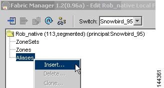
Follow these steps to create the same configuration using Fabric Manager.
Step 1
snmp-server user admin network-admin auth md5 mypasswordStep 2
Step 3
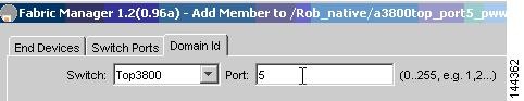
Step 4
The alias named a3800top_port5_pwwn is created with members Brocade domain port of 8,5 and MDS 9000 switch member pWWN 21:00:00:20:37:5b:c8:e7.
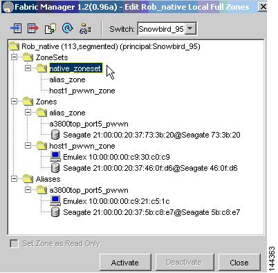
Step 5
Step 6
Step 7
Now you can create the second zone, host1_pwwn_zone, with Brocade member pWWN 21:00:00:20:37:46:0f:d6 and MDS 9000 switch member pWWN 10:00:00:00:c9:30:c0:c9 by following the same steps as previously described.
Step 1
Step 2
Using the Cisco MDS SAN-OS CLI
Follow these steps to create the same configuration using the Cisco MDS SAN-OS CLI.
Step 1
MDS_5# show fcns database vsan 113VSAN 113:--------------------------------------------------------------------------FCID TYPE PWWN (VENDOR) FC4-TYPE:FEATURE--------------------------------------------------------------------------0x0500ca NL 22:00:00:20:37:5a:7f:5a (Seagate) scsi-fcp:target0x0500cc NL 22:00:00:20:37:60:9c:ae (Seagate) scsi-fcp:target0x0500cd NL 22:00:00:20:37:6e:fc:97 (Seagate) scsi-fcp:target0x0500ce NL 22:00:00:20:37:46:0f:d6 (Seagate) scsi-fcp:target0x0500d1 NL 22:00:00:20:37:5b:c8:e7 (Seagate) scsi-fcp:target0x0500d3 NL 22:00:00:20:37:5a:63:06 (Seagate) scsi-fcp:target0x0500d5 NL 22:00:00:20:37:73:3b:20 (Seagate) scsi-fcp:target0x050100 N 10:00:00:05:30:00:87:a3 (Cisco) ipfc0x050101 N 10:00:00:00:c9:30:c0:c9 (Emulex) scsi-fcp:init0x060002 N 10:00:00:0b:46:79:f2:45 (Cisco) ipfc0x081500 N 10:00:00:00:c9:21:c5:1c (Emulex) scsi-fcp:init0x0916ca NL 21:00:00:20:37:5a:7f:5a (Seagate) scsi-fcp:target0x0916cc NL 21:00:00:20:37:60:9c:ae (Seagate) scsi-fcp:target0x0916cd NL 21:00:00:20:37:6e:fc:97 (Seagate) scsi-fcp:target0x0916ce NL 21:00:00:20:37:46:0f:d6 (Seagate) scsi-fcp:target0x0916d1 NL 21:00:00:20:37:5b:c8:e7 (Seagate) scsi-fcp:target0x0916d3 NL 21:00:00:20:37:5a:63:06 (Seagate) scsi-fcp:target0x0916d5 NL 21:00:00:20:37:73:3b:20 (Seagate) scsi-fcp:targetStep 2
MDS_5# conf tEnter configuration commands, one per line. End with CNTL/Z.MDS_5(config)# fcalias name a3800top_port5_pwwn vsan 113MDS_5(config-fcalias)# member domain-id 8 port-number 5MDS_5(config-fcalias)# member pwwn 22:00:00:20:37:5b:c8:e7Step 3
MDS_5(config)# zoneset name native_zoneset vsan 113MDS_5(config-zoneset)# zone name alias_zoneMDS_5(config-zoneset-zone)# member fcalias a3800top_port5_pwwnMDS_5(config-zoneset-zone)# member pwwn 21:00:00:20:37:73:3b:20MDS_5(config-zoneset)# zone name host1_pwwn_zoneMDS_5(config-zoneset-zone)# member pwwn 10:00:00:00:c9:30:c0:c9MDS_5(config-zoneset-zone)# member pwwn 21:00:00:20:37:46:0f:d6Step 4
MDS_5(config)# zoneset activate name native_zoneset vsan 113Zoneset activation initiated. check zone status
Verifying Zone Set and Configuration Activation
Use the following commands to view the MDS 9000 switch and Brocade switches in the fabric to verify the defined zoning is in place. Zoning could have been created by any MDS 9000 switch or any Brocade switch, using either the CLI or the GUI.
MDS Show Commands
Step 1
MDS_5# show zoneset active vsan 113zoneset name native_zoneset vsan 113zone name alias_zone vsan 113* fcid 0x0916d5 [pwwn 21:00:00:20:37:73:3b:20]* fcid 0x081500 [domain-id 8 port-number 5]* fcid 0x0500d1 [pwwn 22:00:00:20:37:5b:c8:e7]zone name host1_pwwn_zone vsan 113* fcid 0x050101 [pwwn 10:00:00:00:c9:30:c0:c9]* fcid 0x0916ce [pwwn 21:00:00:20:37:46:0f:d6]
Note
Step 2
Note
MDS_5# show zoneset vsan 113zoneset name native_zoneset vsan 113zone name alias_zone vsan 113pwwn 21:00:00:20:37:73:3b:20fcalias name a3800top_port5_pwwn vsan 113domain-id 8 port-number 5pwwn 22:00:00:20:37:5b:c8:e7zone name host1_pwwn_zone vsan 113pwwn 10:00:00:00:c9:30:c0:c9pwwn 21:00:00:20:37:46:0f:d6MDS_5# show zoneset brief v 113zoneset name native_zoneset vsan 113zone alias_zonezone host1_pwwn_zoneMDS_5# show fcalias vsan 113fcalias name a3800top_port5_pwwn vsan 113domain-id 8 port-number 5pwwn 22:00:00:20:37:5b:c8:e7
Brocade Show Commands
The Brocade defined configuration is comparable to the MDS 9000 switch full zone database, and the effective configuration is comparable to the MDS 9000 switch active zone set. No matter where the zone set is activated, both should be the same because the MDS 9000 switch follows the Brocade standard of sending all zone database and alias information when activating a zone set.
Top3800:admin> cfgshowDefined configuration:cfg: native_zonesetalias_zone; host1_pwwn_zonezone: alias_zone21:00:00:20:37:73:3b:20; a3800top_port5_pwwnzone: host1_pwwn_zone10:00:00:00:c9:30:c0:c9; 21:00:00:20:37:46:0f:d6alias: a3800top_port5_pwwn8,5; 22:00:00:20:37:5b:c8:e7Effective configuration:cfg: native_zonesetzone: alias_zone21:00:00:20:37:73:3b:208,522:00:00:20:37:5b:c8:e7zone: host1_pwwn_zone10:00:00:00:c9:30:c0:c921:00:00:20:37:46:0f:d6