Table Of Contents
Cisco Wireless Mesh Networking
Point-to-Multipoint Wireless Bridging
Point-to-Point Wireless Bridging
Wireless Mesh Bridge Connections
Mesh Neighbors, Parents, and Children
Multiple Wireless Mesh Mobility Groups
Layer 2 Versus Layer 3 Encapsulation
Indoor WLAN Network to Outdoor Mesh
Connecting the Cisco 1500 Mesh AP to your Network
Physical Placement of Outdoor Mesh APs
Cisco Wireless Mesh Networking
The Cisco Wireless Mesh Network solution enables cost-effective, scalable deployment of secure outdoor wireless LANs, providing access to fixed and mobile applications to enhance public safety, efficiency, productivity, and responsiveness.
The design and deployment of Cisco Wireless Mesh Networks solution is too large a topic to be included in this design guide, which is focused on indoor enterprise WLAN deployments. This chapter provides an overview of the Cisco Wireless Mesh Network solution, because its integration into the Cisco Unified Wireless Network Architecture makes it a simple choice for those customers wishing to extend their enterprise WLAN outdoors.
Overview
In the wireless mesh deployment, multiple Cisco 1500 Mesh APs are deployed as part of the same network (see Figure 10-1).
Figure 10-1 Wireless Mesh Deployment
One or more of the Cisco 1500 Mesh APs have a wired connection to their wireless LAN controller, and these are designated as rooftop mesh APs (RAPs). Other Cisco 1500 Mesh APs that relay their wireless connections to connect to the controller are called mesh access points (MAPs). The MAPs use the AWP protocol to determine the best path to their controller through other Cisco 1500 Mesh APs. The various possible paths between the MAPs and RAPs form the wireless mesh that is used to carry traffic from WLAN clients connected to MAPs in that mesh, and also to carry traffic from devices connected to the MAP Ethernet ports.
The WLAN mesh can simultaneously carry two different traffic types: WLAN client traffic and MAP bridge traffic. WLAN client traffic terminates on the WLAN controller, and the bridge traffic terminates on the Ethernet ports of the Cisco 1500 Mesh APs. Mesh membership in the WLAN mesh is controlled in a variety of ways. MAC authentication of the Cisco 1500 Mesh APs can be enabled to ensure that the APs are included in a database of APs that are authorized to use the WLAN controller. Cisco 1500 Mesh APs are configured with a shared secret for secure AP-to-AP intercommunication, and a bridge group name can be used to control mesh membership, or segmentation. The configuration of these features is covered later in this document.
Wireless Backhaul
Cisco 1500 Mesh APs can provide a simple wireless backhaul solution, where the Cisco 1500 Mesh AP is used to provide 802.11b/g services to WLAN and wired clients. This configuration is basically a wireless mesh with one MAP. Figure 10-2 provides an example of this deployment type.
Figure 10-2 Wireless Backhaul
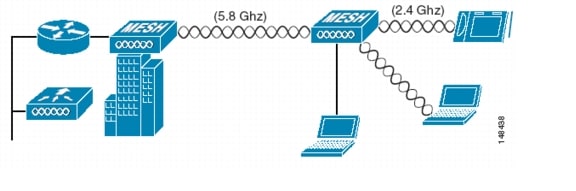
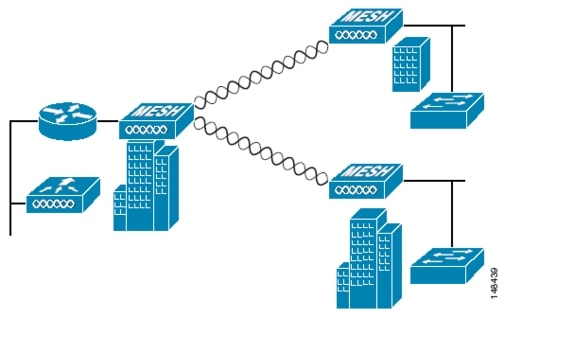
Point-to-Multipoint Wireless Bridging
In the point-to-multipoint bridging scenario, a RAP serving as a root bridge connects multiple MAPs to their associated wired LANs as non-root bridges. By default, this feature is disabled for all MAPs.
If Ethernet bridging is used, you must enable it on the controller for each MAP. Figure 10-3 shows a simple deployment with one RAP and two MAPs, but this configuration is fundamentally a wireless mesh with no WLAN clients. Client access can still be provided with Ethernet bridging enabled, although if bridging between buildings, MAP coverage from a high rooftop might not be suitable for client access.
Figure 10-3 Point-to-Multipoint Wireless Bridging
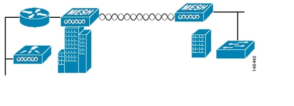
Point-to-Point Wireless Bridging
In a point-to-point bridging scenario, a Cisco 1500 Mesh AP can be used to extend a Layer 2 network by using the backhaul radio to bridge two segments of a switched network, as shown in Figure 10-4. This is fundamentally a wireless mesh with one MAP and no WLAN clients. Just as in point-to-multipoint networks, client access can still be provided with Ethernet bridging enabled, although if bridging between buildings, MAP coverage from a high rooftop might not be suitable for client access.
Figure 10-4 Point-to-Point Wireless Bridging
Wireless Mesh Bridge Connections
The Ethernet ports of the Cisco 1500 Mesh AP are bridged with the wireless mesh acting as a transparent bridge between all Ethernet ports of nodes within that mesh. For example, the simple mesh shown in Figure 10-5 results in a logical multi-port bridge of all Ethernet ports, as shown in Figure 10-6.
Figure 10-5 Simple Mesh Example
Figure 10-6 Wireless Mesh Virtual Multi-Port Bridge
Note that the controller does not participate in this bridging, and that the traffic terminates at the Cisco 1500 AP Ethernet port. Take care to block unnecessary multicast traffic in bridge deployments to prevent wireless backhaul capacity from being consumed unnecessarily.
Also note that for bridged traffic, the controller does not act as a central coordination point. The data traffic for the multipoint bridge is simply bridging traffic through the shortest path calculated by the AWP protocol. The bridge network is transparent to dot1q and Spanning Tree protocols.
Bridge Authentication
When a Cisco 1500 Mesh AP comes up in a mesh, it uses its primary key to authenticate to a parent or a neighboring Cisco 1500 Mesh AP (see Mesh Neighbors, Parents, and Children for more information). Using this primary key, there is a four-way handshake to establish an AES-encrypted session. The new AP establishes an LWAPP tunnel to the controller and is then authenticated against the MAC filter list of the controller. Next, the controller pushes the bridge shared secret key to the AP via LWAPP, after which it re-establishes the AES-encrypted session with the parent AP.
Wireless Mesh Encryption
As previously described, the wireless mesh bridges traffic between the MAPs and the RAPs. This traffic can be from wired devices being bridged by the wireless mesh, or LWAPP traffic from the mesh APs. This means that the wireless mesh can be carrying traffic that is either clear text or encrypted; this traffic is always AES encrypted when it crosses a wireless link.
The AES encryption is established as part of the mesh AP establishing neighbor relationships with other mesh APs. The bridge shared secret is used to establish unique encryption keys between mesh neighbors.
Simple Mesh Deployment
The key components of the simple mesh deployment design (see Figure 10-6) are as follows:
•
A WCS-Key component for the management, operation, and optimization of the mesh network
•
•
The router also provides Layer 2 isolation of the RAP. This is necessary because the RAP bridges traffic from its local Ethernet port to the mesh, so this traffic must be limited to that necessary to support the solution so that resources are not consumed by the unnecessary flooding of traffic.
•
•
Note
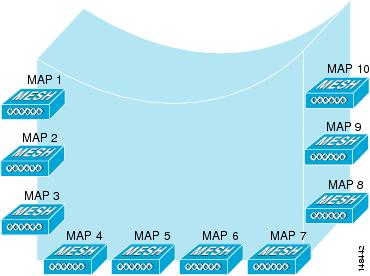
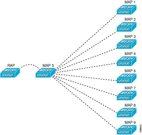
Figure 10-7 shows one possible logical view of the physical configuration shown in Figure 10-5, with MAP5 as the path home for all other MAPs.
Figure 10-7 Logical View
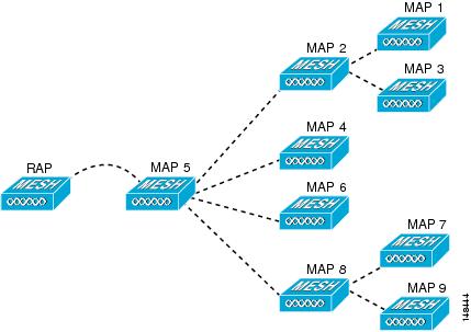
Figure 10-8 shows an alternate logical view, in which the signal-to-noise ratio (SNR) on the diagonal paths to MAP5 is small enough for the MAPs to consider taking an extra hop to get to MAP5.
In both of these cases, MAP5 is the path home for all traffic. Ideally, the coverage from the RAP should be such that other MAPs, such as MAP2 for example, have a path back to the RAP so traffic can be routed via MAP 2 in case of a loss of signal to MAP 5.
Figure 10-8 Unequal Paths
Mesh Neighbors, Parents, and Children
Ease is calculated using the SNR and hop value of each neighbor, and applying a multiplier based on various SNR thresholds. The purpose of this multiplier is to apply a spreading function to the SNRs that reflects various link qualities. A neighbor within a mesh is an AP that is within RF range that has not been selected as a parent or a child because its "ease" values are lower than another neighboring AP.
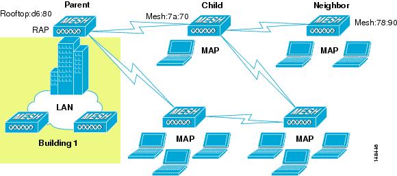
A parent AP is one that is selected as the best route back to the RAP based on the best ease values. A parent can be either the RAP itself or another MAP. A child of an AP is an AP that has selected the parent AP as the best route back to the RAP (see Figure 10-9.)
Figure 10-9 Parent, Child, and Neighbor
Design Details
Each outdoor wireless mesh deployment is unique, and each environment has its own challenges with available locations, obstructions, and network infrastructure availability, in addition to the design requirements based on users, traffic, and availability. This section covers important design considerations and provides an example of a wireless mesh design.
Wireless Mesh Constraints
When designing and building a wireless mesh network with the Cisco 1500 Mesh AP, there are a number of system characteristics to consider. Some of these apply to the backhaul network design and others to the LWAPP controller design. The recommended backhaul is 18 Mbps. 18 Mbps was chosen as the optimal backhaul rate because it aligns with the maximum coverage of the WLAN portion of the client WLAN of the MAP; that is, the distance between MAPs using 18 Mbps backhaul should allow for seamless WLAN client coverage between the MAPs.
A lower bit rate can allow a greater distance between Cisco 1500 Mesh APs, but there are likely to be gaps in the WLAN client coverage, and the capacity of the backhaul network is reduced. An increased bit rate for the backhaul network either requires more Cisco 1500 Mesh APs, or results in a reduced SNR between mesh APs, limiting mesh reliability and interconnection. The wireless mesh backhaul bit rate, like the mesh channel, is set by the RAP.
The number of backhaul hops is limited to eight, but Cisco recommends that you limit the number of hops to three or four, primarily to maintain sufficient backhaul throughput because each mesh AP uses the same radio for transmission and reception of backhaul traffic. This means that throughput is approximately halved over every hop. For example, the maximum throughput for an 18 Mbps is approximately 10 Mbps for the first hop, 5 Mbps for the second hop, and 2.5 Mbps for the third hop.
There is no current software limitation of how many MAPs per RAP you can configure. However, Cisco recommends that you limit this to 20 MAPs per RAP.
The number of APs per controller is determined by the controller capacity:
•
•
•
•
The number of controllers per mobility group is limited to 24.
Client WLAN
The mesh AP client WLAN delivers all the WLAN features derived by a standard LWAPP deployment for b/g clients with the full range of security and radio management features.
The goals of the client WLAN must be considered in the overall mesh deployment:
•
Higher bit rates reduce coverage and are limited by the mesh backhaul.
•
•
•
Is the coverage between different Cisco 1500 Mesh APs required to be contiguous, or is the mesh deployment a collection of separate active zones?
Design Example
This section provides a sample design of providing WLAN coverage in an urban or suburban area.
Cell Planning and Distance
The starting point is the RAP-to-MAP ratio. There is currently no hard limitation of MAPs per RAPs, but the current recommended maximum number is 20 MAPs per RAP.
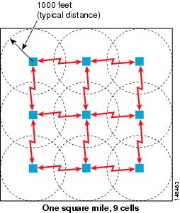
For the backhaul, there is a typical cell size radius of 1000 feet. One square mile in feet is 5280^2 square feet, so the number of cells comes out to be nine, and you can cover one square mile with approximately three or four hops (see Figure 10-10).
Figure 10-10 1000 Feet
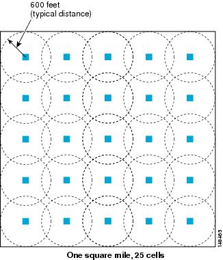
For 2.4 GHz, the local access cell size radius is 600 feet. One cell size comes out to be 1.310 x 10 ^6 square feet, so the number of cells is 25 per square mile (see Figure 10-11).
Figure 10-11 600 Feet
The RAP shown in Figure 10-12 is simply a place holder. The goal is to use the RAP location in combination with RF antenna design to ensure that there is a good RF link to the MAPs within the core of the cell. This means that the physical location of the RAP can be on the edge of the cell, and a directional antenna is used to establish a link into the center of the cell.
Figure 10-12 Schematic of the Wireless Mesh Layout
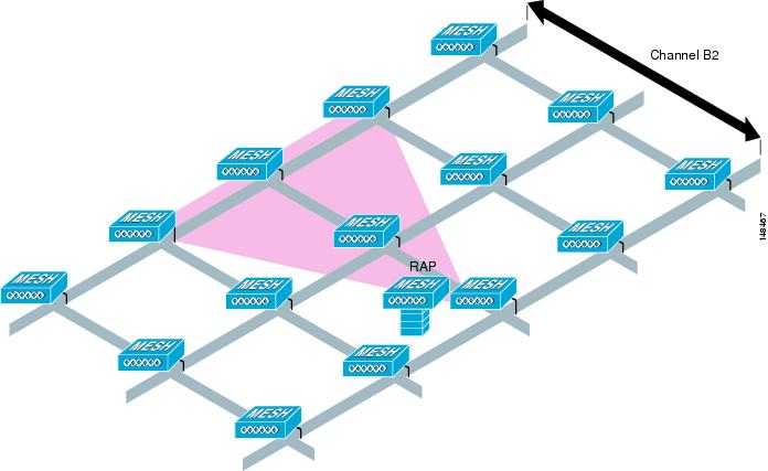
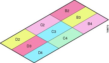
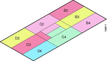
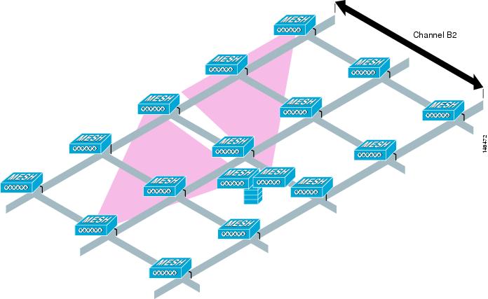
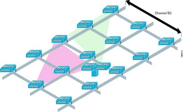
When laying out multiple cells, use channel planning similar to standard WLAN planning to avoid overlapping channels, as shown in Figure 10-13. If possible, the channel planning should also minimize channel overlap in cases where the mesh has expanded to cover the loss of a RAP connection, as shown in Figure 10-14.
Figure 10-13 Laying out Various Cells
Figure 10-14 Failover Coverage
Note
For more information on cell and channel planning including multiple RAP and channels, see the Cisco Aironet 1500 Series Wireless Mesh AP Version 5.0 Design Guide at the following URL: http://www.cisco.com/en/US/docs/wireless/technology/mesh/design/guide/MeshAP.html.
Controller Planning
A mobility group can have up to 24 WLCs, and WLCs can currently support up to 150 APs; with 24 controllers, this provides a maximum of 3600 APs.
In most cases, the full controller capacity is not normally used in this manner, because some of the controllers are used to increase availability; for example, an n+1 system with 23 active controllers and one controller providing backup services.
Another factor that affects the total number of APs is the wired network connecting the RAPs and controllers. If this network allows the controllers to be equally available to all APs without any impact on WLAN performance, the APs can be evenly distributed across all controllers for maximum efficiency.
If this is not the case, and controllers are grouped into various clusters or PoPs, the overall number of APs and therefore coverage are reduced.
Multiple Wireless Mesh Mobility Groups
Keep in mind that wireless mesh built by the maximum number of controllers in a mobility group is not truly the maximum size of WLAN coverage because this is simply the maximum size of the mobility group. The WLANs that are part of a mobility group can be replicated in another mobility group, and a WLAN client is able to roam between these mobility groups.
When roaming between mobility groups, the roaming can be Layer 2 roaming or Layer 3 roaming, depending on the network topology behind the wireless mesh networks.
Increasing Mesh Availability
In the previous section, a wireless mesh cell of one square mile was created and then built upon. This wireless mesh cell has similar properties to the cells used to create a cellular phone network; that is, although the technology might define the maximum size of the cell, smaller cells can be created to cover the same physical area, providing greater availability or capacity. This is done by adding RAPs to the cell. Just as in the larger mesh deployment, the decision is whether to use RAPs on the same channel, as shown in Figure 10-15, or to use different channels, as shown in Figure 10-16. The addition of RAPs into an area adds capacity and resilience to that area.
Figure 10-15 Two RAPs per Cell with the Same Channel
Figure 10-16 Two RAPs per Cell on Different Channels
Layer 2 Versus Layer 3 Encapsulation
Cisco generally recommends using Layer 3 encapsulation because it gives greater flexibility in RAP and controller placement. Even if it is possible to put the RAP and its associated controllers on the same subnet, Cisco recommends that the RAP and the controllers be separated by a router hop, because this controls the Layer 2 traffic going into the RAP Ethernet interface, and simplifies the network design if more RAPs or controllers need to be added.
Multiple RAPs
If multiple RAPs are to be deployed, the purpose for deploying these RAPs needs to be considered. If the RAPs are being deployed to provide hardware diversity, the additional RAPs should be deployed on the same channel as the primary RAP to minimize the convergence time in a scenario where the mesh transfers from one RAP to another. When planning RAP hardware diversity, remember the 32 MAPs per RAP limitation.
If the additional RAPs are being deployed to primarily provide additional capacity, deploy the additional RAPs on a different channel to its neighboring RAPs to minimize the interference on the backhaul channels.
If the mesh AP bridging features are being used with multiple RAPs, these RAPs should all be on the same subnet to ensure that a consistent subnet is provided for bridge clients.
If you build your mesh with multiple RAPs on different subnets, MAP convergence times increase if a MAP has to failover to another RAP on a different subnet. One way to limit this from happening is to use different BGNs for segments in your network that are separated by subnet boundaries.
Multiple Controllers
The consideration in distance of the LWAPP controllers from other LWAPP controllers in the mobility group, and the distance of the LWAPP controllers from the RAPs, is similar to the consideration of an LWAPP WLAN deployment in an enterprise.
There are operational advantages to centralizing LWAPP controllers, and these advantages need to be traded off against the speed and capacity of the links to the LWAPP APs and the traffic profile of the WLAN clients using these APs.
If the WLAN client traffic is expected to be focused on particular sites such as the Internet or a data center, centralizing the controllers at the same sites as these traffic focal points gives the operational advantages without sacrificing traffic efficiency.
If the WLAN client traffic is more peer-to-peer, a distribute controller model might be a better fit; it is likely that a majority of the WLAN traffic are clients in the area, with a smaller amount of traffic going to other locations. Given that many peer-to-peer applications can be sensitive to delay and packet loss, it is best to ensure that traffic between peers takes the most efficient path.
Given that most deployments see a mix of client server traffic and peer-to peer traffic, it is likely that a hybrid model of LWAPP controller placement is used, where points of presence (PoPs) are created with clusters of controllers placed in strategic locations in the network.
In all cases, remember that the LWAPP model used in the wireless mesh network is designed for campus networks; that is, it expects a high-speed, low-latency network between the LWAPP APs and the LWAPP controller.
Indoor WLAN Network to Outdoor Mesh
Mobility groups can be shared between outdoor mesh networks and indoor WLAN networks. It is also possible for a controller to control indoor LWAPP APs and Cisco 1500 Mesh APs simultaneously. The same WLANS are broadcast out both the indoor AP as well as the Cisco 1500 Mesh APs.
Adding outdoor mesh networks in an enterprise campus network enables new mobility applications. Voice clients are able to take their calls in motion from one building to another on the same WLANs they have inside the buildings. Security can also benefit from this new outdoor wireless network. Video streaming to security officer vehicles from outdoor and indoor cameras, access to data from the network, as well as transmitting data voice and video from the vehicle are all enabled. Because of the fast secure roaming enabled by the controllers and APs, outdoor applications can now move around the campus.
Outdoor Mesh Controllers
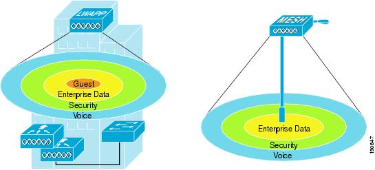
You can either associate your outdoor mesh APs with the same controllers you are using for your indoor enterprise network, or you can have a separate controller or pool of controllers just for your outdoor network. If you choose to use the same controllers for both your indoor and outdoor network, take into consideration that there might be some WLANs you do not want on your outdoor network. In this case, use the WLAN override option under the b radio configuration on your outdoor mesh APs to disable specific WLANs. For example, you might not want to have your guest access network enabled on the outdoor network. Figure 10-17 displays this example.
The other option is to have a separate pool of controllers just for your outdoor network. This way allows you to configure and control all your WLANs on a per controller basis without having to disable certain WLANs on every outdoor MESH AP. If you take this approach, you must configure the mobility groups between your designated outdoor controllers and your indoor controllers to provide seamless roaming for clients between the two networks.
Figure 10-17 Indoor Outdoor WLANs
Connecting the Cisco 1500 Mesh AP to your Network
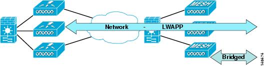
The wireless mesh has two locations where traffic terminates on the wired network. The first location is where the RAP attaches to the wired network, and where all bridged traffic connects to the wired network. The second location is where the LWAPP controller connects to the wired network; this is where WLAN client traffic from the mesh network connects to the wired network. This is shown schematically in Figure 10-18. The WLAN client traffic from LWAPP is tunneled at Layer 2, and matching WLANs should terminate on the same switch VLAN as where the controllers are co-located. The security and network configuration for each of the WLANs on the mesh depend on the security capabilities of the network to which the controller is connected.
Figure 10-18 Mesh Network Traffic Termination
Indoor LWAPP APs do not need a firewalled connection like the outdoor APs. This is because their interfaces are on a secure indoor network and all traffic is tunneled to the controllers, unlike the outdoor APs that can be used for a bridging application.
Physical Placement of Outdoor Mesh APs
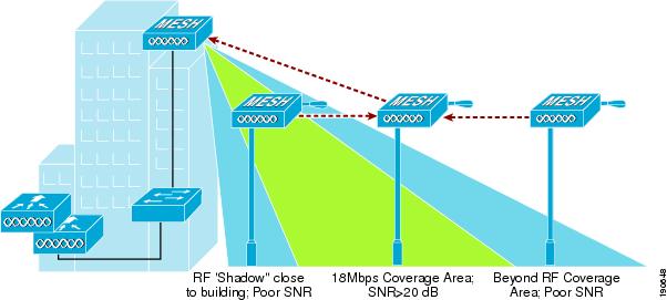
When choosing a location for your APs on the campus, keep in mind issues such as building height obstructions, light pole locations, and power options. There are light poles on most enterprise campuses, but not all of them are equipped with a electric eye. Make note of what types of light poles you have and options for taping power. When placing the roof top AP, a directional antenna might be of use to direct coverage to a specific MAP or group of MAPs designated as the first hops into the mesh. If you plan to use an omni-directional antenna for the RAP, make sure to mount it towards the edge of the building so the radio coverage is not blocked by the edge of the building. Figure 10-19 shows coverage concerns between the RAP and MAPs in the mesh.
Figure 10-19 AP Placement
For more information on MESH QoS, Cisco Adaptive Wireless Path (AWP) protocol, mesh traffic flow, Ease, and CLI commands, see the Cisco Aironet 1500 Series Wireless Mesh AP Version 5.0 Design Guide at the following URL: http://www.cisco.com/en/US/docs/wireless/technology/mesh/design/guide/MeshAP.html.