Table Of Contents
Cisco Unified Wireless Location-Based Services
Cisco Location-Based Services Architecture
Role of the Cisco Wireless Location Appliance
Installation and Configuration
Installing and Configuring the Location Appliance and WCS
Location-Aware WLAN Design Considerations
SOAP/XML Application Programming Interface
Cisco Unified Wireless Location-Based Services
Introduction
With integrated location tracking, enterprise wireless LANs become much more valuable as a corporate business asset. Enterprise network administrators, security personnel, and others directly responsible for the health and well-being of business-class networks have expressed great interest in location-based services to allow them to better address issues in their environments such as the following:
•
Quickly and efficiently locating valuable assets and key personnel
•
•
•
•
•
•
This chapter discusses the Cisco Location-Based Service (LBS) solution and the areas that merit special consideration involving design, configuration, installation, and deployment. Each of these areas is described in brief and reference is made to a comprehensive white paper entitled Wi-Fi Location-Based Services 4.1 Design Guide, which contains in-depth discussion and analysis and is available at the following URL: http://www.cisco.com/en/US/docs/solutions/Enterprise/Mobility/WiFiLBS-DG.html. This chapter addresses the following topics:
•
•
•
•
•
Reference Publications
This document makes extensive reference to the following white paper, which should be referenced for further detailed information regarding any section in this chapter:
•
Additionally, review the following supplemental documents:
•
•
•
•
•
In addition, Cisco recommends that you review Chapter 8, "Cisco Unified Wireless Control System," in this design guide.
Cisco Location-Based Services Architecture
Positioning Technologies
Location tracking and positioning systems can be classified by the measurement techniques they employ to determine mobile device location (localization). These approaches differ in terms of the specific technique used to sense and measure the position of the mobile device in the target environment under observation. Typically, Real Time Location Systems (RTLS) can be grouped into four basic categories of systems that determine position on the basis of the following:
•
•
•
•
An RTLS system designer can choose to implement one or more of these techniques. This may be clearly seen in some approaches attempting to optimize performance in two or more environments with very different propagation characteristics. An example of this is an RTLS system attempting to yield optimal performance for both indoor and outdoor applications by using two different techniques. It is not unusual to hear arguments supporting the case for a fifth category that encompasses RTLS systems that sense and measure position using a combination of at least two of these methods.
Keep in mind that regardless of the underlying positioning technology, the "real-time" nature of an RTLS is only as real-time as the most current timestamps, signal strengths, or angle-of-incidence measurements. The timing of probe responses, beaconing rates, and location server polling intervals can introduce discrepancies seen between actual and reported device position from one reporting interval to another.
The "Location Tracking Approaches" section of Wi-Fi Location-Based Services 4.1 Design Guide provides a foundation in the technical aspects of traditional location tracking and positioning systems. To better comprehend the differences between traditional approaches and RF Fingerprinting, this section is highly recommended reading, because it thoroughly explains the concepts of cell of origin, time of arrival (ToA), time difference of arrival (TDoA), angle of arrival (AoA), and location patterning.
What is RF Fingerprinting?
Cisco RF Fingerprinting refers to a new and innovative approach that significantly improves the accuracy and precision available with traditional signal strength lateration techniques. Cisco RF Fingerprinting offers the simplicity of an RSSI-based lateration approach with customized calibration capabilities and improved indoor performance.
RF Fingerprinting significantly enhances RSS lateration through the use of RF propagation models developed from data gathered in the target environment or environments very similar to it. RF Fingerprinting offers the ability to calibrate an RF model to a particular environment in a fashion similar to (but more expeditious than) that of location patterning. But unlike location patterning, a unique custom site calibration is not always required, especially in situations where multiple floors of similar construction, contents, and layout are deployed.
Cisco RF fingerprinting offers several other key advantages over the approaches described in the "Location Tracking Approaches" section of Wi-Fi Location-Based Services 4.1 Design Guide:
•
•
•
•
•
Additional information regarding RF Fingerprinting and all four of these key advantages can be found in the "Location Based Services Architecture" section of Wi-Fi Location-Based Services 4.1 Design Guide.
Overall Architecture
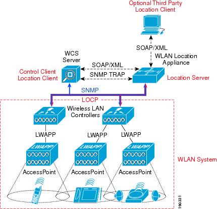
The overall architecture of Cisco LBS is shown in Figure 15-1.
Figure 15-1 Cisco Location-Based Services Solution Architecture
Access points forward received signal strength information to WLAN controllers with regard to the observed signal strength of any Wi-Fi clients, 802.11 active RFID tags, rogue access points, or rogue clients. In normal operation, access points focus their collection activities for this information on their primary channel of operation, going off-channel and scanning the other channels in the regulatory channel set of the access point periodically. The collected information is forwarded to the WLAN controller to which the access point is currently registered. Each controller manages and aggregates all such signal strength information coming from its access points. The location appliance uses SNMP to poll each controller for the latest information regarding each tracked category of devices. In the case of a location tracking system deployed without a location appliance, the Cisco Wireless Control System (WCS) retrieves this information from the appropriate controller(s) directly.
WCS and the location appliance exchange information regarding calibration maps and network designs during a process known as synchronization. During a network design synchronization between WCS and the location appliance, the "up-to-date" partner updates the design and calibration information of the "out-of-date" partner. The location appliance synchronizes with each controller containing access points participating in location tracking during controller synchronization. Synchronization occurs either on-demand or as a scheduled task, the timing of which is determined by the Administration > Scheduled Tasks main menu option under the WCS main menu bar.
Location information is displayed to the end user using a location client application in conjunction with the Cisco Wireless Location Appliance. Typically this role is fulfilled by the Cisco WCS.
Note
As described in subsequent sections of this document, the WCS is capable of displaying a wide range of information regarding the location of clients, asset tags, rogue access points, and rogue clients. However, location client functionality is not limited to WCS. Other third-party applications may be written in accordance with the Cisco Location Appliance Application Programming Interface (API) as well. Using the Simple Object Access Protocol (SOAP)/Extensible Markup Language (XML) protocol, these applications can also serve as location clients to the Wireless Location Appliance (see Figure 15-1). The Cisco Location Appliance is also capable of issuing notifications to external systems via e-mail (SMTP), Syslog, SNMP traps, or the SOAP/XML protocol.
Note
Role of the Cisco Wireless Location Appliance
When a Cisco Location Appliance is added into a Cisco LWAPP-enabled Unified Wireless Network with an appropriately licensed version of WCS, the location appliance assumes responsibility for several important tasks. Key among these are the execution of positioning algorithms, maintenance of calibration information, triggering and dispatch of location notifications, and the ongoing processing of historical location and statistics information. WCS acts in concert with the location appliance by serving as the user interface (UI) for the services the location appliance provides. Although it is possible to access the location appliance directly via SSH or a console session, all end user interaction with the location appliance is typically via WCS or a third-party location client application (except for initial setup of the location appliance and whenever it is necessary to quiesce the appliance).
The integration of a Cisco Location Appliance into a Cisco Unified Wireless Network architecture immediately enables improvements in network location capabilities such as the following:
•
•
•
•
Solution Performance
When discussing the performance of a positioning system, the metric that is most familiar and significant is accuracy, which typically refers to the quality of the information being received. Location accuracy refers specifically to the quantifiable error distance between the estimated location and the actual location of the mobile device.
In most real-world applications, however, a statement of location accuracy has little value without the ability of the solution to repeatedly and reliably perform at this level. Precision is a direct measure reflecting on the reproducibility of the stated location accuracy. Any indication of location accuracy should therefore include an indication of the confidence interval or percentage of successful location detection as well, otherwise known as the location precision.
When properly deployed, the accuracy and precision of the Cisco LBS solution in indoor deployments is represented in two ways, as follows:
•
•
In other words, given proper design and deployment of the system, the error distance between the reported device location and the actual location should, in 90 percent of all reporting instances, be within 10 meters or less. In the remaining 10 percent of all reporting instances, the error distance may be expected to exceed 10 meters. Note that these specifications apply only to solutions using RF Fingerprinting; namely, the use of a WCS licensed for location usage (with or without a location appliance).
For applications that require better performance than an accuracy of 10 meters with 90 percent precision, the Cisco LBS solution can deliver accuracy of 5 meters but with 50 percent precision. Or stated another way, in 50 percent of all reporting instances, it can be reasonably expected that the error distance between the reported and the actual location will exceed 5 meters. In addition, the location inspection tool (a new feature with release 4.0 of WCS and 2.1 of the location appliance) can display various levels of accuracy and precision from 2m to 100m and the areas of your environment that can meet these accuracy targets. Using the location inspection tool in conjunction with new predictive tools (available in WCS release 4.0 and Location Appliance release 2.1), such as the location planner and the location readiness, the network designer now can not only plan for achieving stated performance goals but verify that these targets are indeed being met.
What Devices Can Be Tracked
The Cisco LBS solution can provide position tracking information for the following:
•
.
•
.
•
.
Note
Installation and Configuration
Installing and Configuring the Location Appliance and WCS
Detailed procedures for installing and configuring the Cisco Wireless Location Appliance and WCS can be found via the references mentioned in the "Installation and Configuration" section of Wi-Fi Location-Based Services 4.1 Design Guide.
Configuration of the parameters listed under the WCS Location Server > Administration menu are discussed in the document entitled Cisco Location Appliance Configuration Guide: Editing Location Server Properties at the following URL: http://www.cisco.com/en/US/docs/wireless/location/2700/3.0/configuration/guide/lacg_ch4.html.
However, there are additional ramifications associated with making changes to the factory defaults that need to be carefully considered. This and other valuable information that a designer of a location-enabled wireless LAN should consider can be found in the "Installation and Configuration" section in Wi-Fi Location-Based Services 4.1 Design Guide, including the following:
•
–
–
•
–
–
–
–
–
•
–
–
–
–
–
•
•
•
•
•
Deployment Best Practices
Location-Aware WLAN Design Considerations
The past decade has witnessed the best practice design of enterprise-ready wireless LANs evolve from being centered around the model of maximum coverage using minimum AP count to a new model where coverage uniformity and proper cell-to-cell overlap are the predominant criteria. This has been driven by increasing interest in deploying new wireless applications such as wireless voice with its intolerance for large amounts of dropped packets and high roaming delays. In a similar fashion, deploying location-based applications using a Wi-Fi wireless LAN requires a modification of the current approach, both in how new "location-aware" installations are designed, and also in how an existing deployment is augmented or retrofitted to take advantage of new location-tracking applications. For location tracking to function optimally, the correct number of access points along with proper access point placement is necessary to assure that mobile devices are properly detected as they move about in the WLAN environment.
The "Deployment Best Practices" section of Wi-Fi Location-Based Services 4.1 Design Guide discusses in great detail several best-practice recommendations for location-aware WLAN deployments. These best-practice recommendations are briefly described here:
•
•
•
•
•
•
•
•
•
Traffic Considerations
The Cisco Wireless Location Appliance and the Cisco WCS are part of the Cisco Unified Wireless Network with each deployed as a separate hardware component for optimum scalability and maximum flexibility. Generally speaking, when all components are deployed in a campus arrangement via a well-designed 10/100/1000 infrastructure wired LAN, bandwidth is typically sufficient for proper operation of the LBS solution. In deployments supporting a large number of geographically distributed locations, further consideration with regard to data traffic load may be required.
The "Deployment Best Practices" section of Wi-Fi Location-Based Services 4.1 Design Guide provides valuable in-depth discussion and traffic flow analysis of the data flows between the location appliance, WLAN controllers, and WCS.
RFID Tag Considerations
The majority of RFID tags currently produced are passive RFID tags, consisting basically of a micro-circuit and an antenna. They are referred to as passive tags because the only time in which they are actively communicating is when they are within the RF field of a passive RFID tag reader or interrogator.
Another type of common RFID tag in the current marketplace is known as the active RFID tag, which usually contains a battery that directly powers RF communication. This onboard power source allows an active RFID tag to transmit information about itself at great range, either by constantly beaconing this information to a RFID tag reader or by transmitting only when it is prompted to do so. Active tags are usually larger in size and can contain substantially more information (because of higher amounts of memory) than do pure passive tag designs.
The "RFID Tag Considerations" section of Wi-Fi Location-Based Services 4.1 Design Guide provides readers who are new to RFID with a foundation in both active and passive tag technologies. Among other areas, this section comprehensively discusses the following:
•
•
•
SOAP/XML Application Programming Interface
To facilitate the deployment of location-based applications in the enterprise, the Cisco Wireless Location Appliance is equipped with a rich SOAP/XML API. Applications can make use of the location information contained within the location appliance by importing components via the API such as entire network maps including buildings, floors, access points, coverage areas, and device lists. Actionable data can also be imported, such as recent and historical location as well as statistical device information. Location-based alarms and notifications can be triggered in applications through area boundary definitions, allowed areas and allowed distances. All of these capabilities allow the SOAP/XML API interface to the Cisco Wireless Location Appliance API to be used for integration with external software applications such as E911, asset management, enterprise-resource-planning (ERP) tools, and workflow automation systems that are location-enabled.
From a high-level perspective, a third-party application system can use the SOAP/XML API to participate as a member of a system consisting of the following four basic components:
•
•
•
•
The "SOAP/XML Application Programming Interface" section of Wi-Fi Location-Based Services 4.1 Design Guide describes all four of these basic components in much further detail and briefly examines a Cisco Technology Partner location client implementation.