Table Of Contents
Cisco Unified Wireless Guest Access Services
Wireless Guest Access Overview
Wireless Guest Access using a Centralized Controller Architecture
Non-Controller Based Wireless Guest Access
Wireless Controller Guest Access
WLAN Anchors and Ethernet in IP to Support Guest Access
Anchor Controller Deployment Guidelines
Anchor Controller Sizing and Scaling
Local Controller Lobby Admin Access
Anchor Controller Interface Configuration
Guest VLAN Interface Configuration
Anchor Controller DHCP Configuration (Optional)
Adding a New DHCP Scope to the Anchor Controller
Defining a Default Mobility Domain Name for the Anchor Controller (Optional)
Defining Mobility Group Members for the Anchor Controller
Adding an Anchor Controller as a Mobility Group Member in the Remote Controller
Guest WLAN Configuration for the Remote Controller
Guest WLAN Configuration on the Anchor Controller
Guest WLAN Policies for the Anchor Controller
Web Portal Page Configuration and Management
Internal Web Certificate Management
Support for External Web Redirection
Managing Guest Credentials Directly on the Anchor Controller
Configuring the Maximum Number of User Accounts
External Radius Authentication
Verifying Guest Access Functionality
Cisco Unified Wireless Guest Access Services
The introduction of Wireless LAN (WLAN) technologies in the enterprise has changed the way corporations and small-to-medium businesses function by freeing staff and network resources from the constraints of fixed network connectivity.
WLAN has also changed how individuals access the Internet and their corporate networks from public locations. The advent of Public WLAN (Hotspots) has caused mobile workers to become accustomed to being able to access their corporate network from practically anywhere.
Introduction
The paradigm of public access has extended to the enterprise itself. Long gone is the scenario where it was sufficient for a company to provide its partners, visitors, and guests with a place to sit and possibly an outside line with which to make phone calls. Our highly mobile, information-on-demand culture requires on-demand network connectivity. A half-day spent at a partner or customer venue without access to one's own network resources can impact the productivity of a meeting, service or sales call, and reduce the overall personal productivity of the guest who is away from their office. For this reason, enterprise guest access services are becoming increasingly important and a necessity in the corporate environment.
While there is broad recognition that guest networking is becoming increasingly important, there is also well-founded apprehension over how one safeguards their internal company information and infrastructure assets. Ironically, unbeknownst to many enterprises, their network might already play host to guests who, in an uncontrolled manner, find ways to access the Internet via improperly implemented wired or wireless networks. These guests are not hackers in the true sense, but otherwise well-intentioned individuals trying to get their jobs done. So, on the surface, while it might sound risky to implement a guest access solution, when implemented correctly, an enterprise that implements a guest access solution will most likely improve their overall security posture as a result of the network audits associated with the implementation process.
In addition to overall improved security, implementing a guest access network offers these additional general benefits:
•
Authentication and authorization control of guests based on variables including date, duration, and bandwidth
•
Additional benefits of a wireless-based guest access include the following:
•
•
Scope
Several architectures can be implemented to offer guest access in the enterprise. It is not the goal of this chapter to cover all possible solutions. Instead, this chapter focuses on the implementation of wireless guest networking using the Cisco centralized controller and lightweight AP (LWAPP) architecture. For more information on deploying wired and wireless Guest Access services in other topology scenarios, see the following URL: http://www.cisco.com/en/US/docs/solutions/Enterprise/Network_Virtualization/GuestAcc.html.
Wireless Guest Access Overview
Ideally, the implementation of a wireless guest network uses as much of an enterprise's existing wireless and wired infrastructure as possible to avoid the cost and complexity of building a physical overlay network. Assuming this is the case, the following additional elements and functions are needed:
•
•
•
•
Wireless Guest Access using a Centralized Controller Architecture
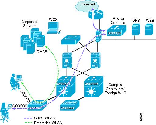
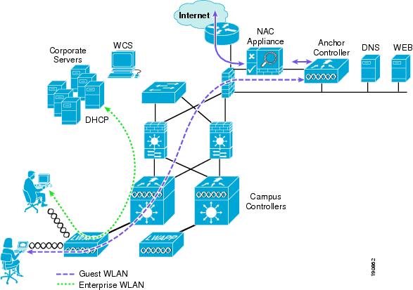
The Cisco Centralized WLAN solution offers a flexible, easy-to-implement method for deploying wireless guest access by using Ethernet in IP (RFC3378) within the centralized architecture. Ethernet in IP is used to create a tunnel across a Layer 3 topology between two WLAN controller endpoints. The benefit of this approach is that there are no additional protocols or segmentation techniques that must be implemented to isolate guest traffic from the enterprise. See Figure 12-1 for an example of guest access topology using a centralized WLAN architecture.
Figure 12-1 Centralized Controller Guest Access
As shown in Figure 12-1, a controller is located in the enterprise's DMZ where it performs an anchor function. This anchor controller is responsible for terminating EoIP tunnels that originate from other campus WLAN controllers throughout the network. Remote controllers are responsible for termination, management, and standard operation of the various WLANs provisioned throughout the enterprise, including one or more guest WLANs. Guest WLANs, instead of being bridged locally to a corresponding VLAN, are bridged via an EoIP tunnel to the anchor controller. Specifically, guest WLAN data frames are bridged via LWAPP to the remote controller and via EoIP for the campus WLC to a guest VLAN defined at the anchor WLC. In this way, guest user traffic is forwarded to the Internet transparently, with no visibility by, or interaction with, other traffic in the enterprise.
Non-Controller Based Wireless Guest Access
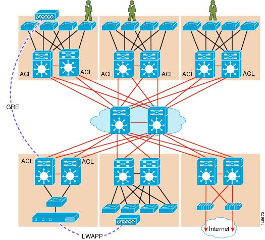
In place of using a centralized WLAN architecture, the biggest challenge in implementing guest access services is the segmentation (isolation) of guest traffic from the rest of the enterprise. This is especially true for wired networks or wireless networks that use autonomous (fat) APs. Some method of traffic segmentation must be implemented beginning with a separate WLAN or VLAN, coupled with a policy that is applied at the first Layer 3 hop in the network. Possible options include the following:
•
Figure 12-2 Segmentation using Distributed ACLs
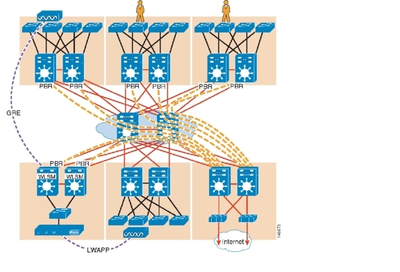
•
Figure 12-3 Segmentation using PBR into GRE Tunnels
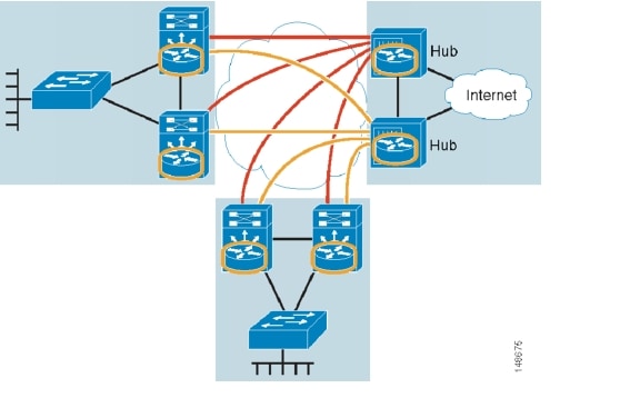
•
Figure 12-4 Segmentation using VRF-lite and GRE
Figure 12-5 Segmentation with VRF-Lite and mGRE
Each of the methods described here has benefits and drawbacks. Additional challenges for the enterprise include the following:
•
•
•
In addition, it simply might not be practical or possible for an enterprise to implement one of the segmentation methods described in this chapter. In that case, and if wireless guest access is all that is needed, deploying guest services using a centralized WLAN controller architecture is a good alternative.
Otherwise, if an enterprise requires both wireless and wired guest access, see the guest access documentation at the following URL: http://www.cisco.com/en/US/docs/solutions/Enterprise/Network_Virtualization/GuestAcc.html.
The remainder of this chapter focuses on the implementation of wireless guest networking using the Cisco Centralized Controller solution.
Wireless Controller Guest Access
The Cisco Wireless Controller Guest Access solution is self-contained and does not require any external platforms to perform access control, web portal, or AAA services. All these functions are configured and run within the anchor controller. However, the option exists to implement one or all of these functions externally and that is covered later in the chapter.
Supported Platforms
The anchor function, which includes tunnel termination, web authentication, and access control is supported on the following WLC platforms (using version 4.0 and later software images):
•
•
•
The following WLC platforms cannot be used for anchor functions, but can be used for normal controller operations and guest tunnel origination to an anchor controller:
•
•
WLAN Anchors and Ethernet in IP to Support Guest Access
A key feature of the Cisco centralized controller architecture is the ability to statically map one or more provisioned WLANs to a specific controller (anchor) within the network, using an EoIP tunnel. By using this technique, a guest WLAN and all associated guest traffic can be transported transparently across the enterprise network to an anchor controller that resides in the Internet DMZ (see Figure 12-6).
Figure 12-6 Static EoIP Tunnels
Figure 12-7 shows a sniffer trace of an Ethernet in IP tunnel (highlighted) between a branch wireless controller with a guest WLAN provisioned and an anchor controller that is performing local web authentication. The first IP detail shown represents the Ethernet in IP tunnel between the branch and anchor controllers. The second IP detail is that of guest traffic (in this case, a DNS query).
Figure 12-7 Sample Ethernet in IP Sniffer Trace
Anchor Controller Deployment Guidelines
This section provides guidelines for deploying an anchor controller to support wireless guest access.
Anchor Controller Positioning
Because the anchor controller is responsible for termination of guest WLAN traffic and subsequent access to the Internet, it should be positioned in the enterprise's Internet DMZ. By doing so, rules can be established within the firewall to precisely manage communications between authorized controllers throughout the enterprise and the anchor controller. Such rules might including filtering on source or destination controller addresses, UDP port 16666 for inter-WLC communication, and IP protocol ID 97 Ethernet in IP for client traffic. Other rules that might be needed include the following:
•
•
•
•
Depending on the topology, the firewall can be used to protect the anchor controller from outside threats.
For the best possible performance and because of its suggested positioning in the network, it is strongly recommended that the guest anchor controller be dedicated to supporting guest access functions only. In other words, the anchor controller should not be used to support guest access in addition to controlling and managing LWAPP APs in the enterprise.
DHCP Services
As previously described, guest traffic is transported at Layer 2 via EoIP. Therefore, the first point at which DHCP services can be implemented is either locally on the anchor controller or the controller can relay client DHCP requests to an external server. See Guest Access Configuration for configuration examples.
Routing
Guest traffic egress occurs at the anchor controller. Guest WLANs are mapped to a specific physical interface or VLAN on the anchor. Depending on the topology, this interface or VLAN might connect to an interface on a firewall, or directly to an Internet border router. Therefore, a client's default gateway IP is either that of the firewall or the address of a VLAN or interface on the first hop router. For ingress routing, it is assumed the guest VLAN is directly connected to a DMZ interface on a firewall or to an interface on a border router. In either case, the guest (VLAN) subnet is known as a directly connected network and advertised accordingly.
Anchor Controller Sizing and Scaling
The most cost-effective platform to support guest networking in most enterprise deployments is the Cisco 4400 Series controller. Assuming the controller is being deployed to support guest access and tunnel termination functions only, the 4402 with support for 12 APs is sufficient because it is assumed the controller is not going to be used to manage LWAPP APs in the network.
A single 4400 Series controller can support EoIP tunnels from up to 40 other controllers within the enterprise. Additionally, the 4400 supports up to 2500 simultaneous users and has a forwarding capacity of 2 Gbps.
Anchor Controller Redundancy
Anchor controller redundancy is expected to be supported in future releases.
Web Portal Authentication
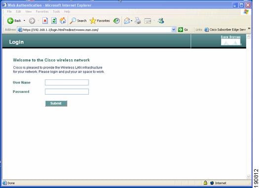
The Cisco Centralized Guest Access solution can make use of a built-in web portal that is used to solicit guest credentials for authentication and offers simple branding capabilities, along with the ability to display disclaimer or acceptable use policy information (see Figure 12-8).
Figure 12-8 Controller Web Authentication Page
The web portal page is available on all Cisco WLAN controller platforms and is invoked by default when a WLAN is configured for Layer 3 web policy-based authentication.
If a more complex page is required, administrators have the option of importing and locally storing a customized page. Additionally, if an enterprise wants to use an external web server, the controller can be configured to redirect to it in place of using the internal server. See Guest Access Configuration for web page configuration guidelines.
User Redirection
As is typical for most web-based authentication access, for guest clients to be redirected to the controller web authentication page, they must launch a web browser session and attempt to open a destination URL. For redirection to work correctly, the following conditions must be met:
•
Note
•
•
Note
Guest Credentials Management
Guest credentials can be created and managed centrally using WCS beginning with release 4.0 and later. A network administrator can establish a limited privilege administrative account within WCS that permits lobby ambassador access for the purpose of creating guest credentials. The only function a lobby ambassador is permitted to do is create and assign guest credentials to a controller serving as an anchor for wireless guest access. See Guest Access Configuration for configuration guidelines.
As with many configuration tasks within WCS, guest credentials are created using templates. For more information regarding administration and use of WCS, see Chapter 8, "Cisco Unified Wireless Control System." A guest user template includes the following information:
•
•
•
•
•
•
After a lobby ambassador has created a guest template, it can be applied to one or more controllers. Only controllers with web policy-configured WLANs are listed as a candidate controller to which the template can be applied.
Guest credentials, when applied, are stored locally on the anchor controller and remain there until expiration of the Lifetime variable defined in the guest template. If a wireless guest is associated and active when their credentials expire, the WLAN controller stops passing traffic from that user, causing them to be disconnected. Unless the guest credentials are re-applied (to the controller), the user is no longer able to authenticate and access the network.
Note
Local Controller Lobby Admin Access
In the event a centralized WCS management system is not deployed, a network administrator can establish a local user management account on the anchor controller, which has lobby admin privileges only. A person who logs in to the controller using the lobby admin account has access only to guest user management functions. Options available for local guest management are the same as for guest template creation in WCS:
•
•
•
•
Only WLAs configured for Layer 3 web policy authentication are displayed.
•
•
Any credentials that may have been applied to the controller by WCS are shown when an admin logs into the controller using the lobby admin account. The lobby admin account has rights to modify or delete any guest credentials that were created by WCS.
Guest User Authentication
As was previously covered in Guest Credentials Management, when an administrator uses WCS or a local admin account on a controller to create guest user credentials, those credentials are stored locally on the controller, which in the case of a centralized guest access topology, would be the anchor controller.
When a wireless guest logs in through the web portal, the controller handles the authentication in the following order:
1.
If no user credentials are found, then:
2.
If no specific RADIUS servers have been configured for the WLAN:
3.
Note
External Authentication
The guest account creation (Lobby Ambassador) capabilities available in WCS and locally on the controller can be used only to create and store guest user information locally on the controller. An enterprise may already have developed similar functionality in conjunction with a wired guest access or NAC-type deployment. In this case, the anchor controller/guest WLAN can be configured to forward web portal authentication to an external RADIUS server, as described in Guest User Authentication.
The default protocol used by the controller to authenticate web users is Password Authentication Protocol (PAP). In the event you are authenticating web users to an external AAA server, be sure to verify the protocols supported by that server. The anchor controller can also be configured to use CHAP or MD5-CHAP for web authentication. The method is configured under the general configuration settings of the controller by using the web administrative interface of the controller, or through WCS.
External Authentication using Cisco Secure ACS and Microsoft User Databases
If a guest access deployment is planning to use a Microsoft user database in conjunction with Cisco ACS to authenticate guest users, see the following additional Cisco ACS configuration caveats: http://www.cisco.com/en/US/docs/net_mgmt/cisco_secure_access_control_server_for_windows/4.0/installation/guide/windows/postin.html.
Guest Pass-through
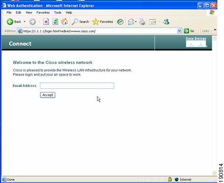
Another variation of wireless guest access is to bypass user authentication altogether and allow open access. However, an enterprise might still want to present an acceptable use policy or disclaimer page to users before granting access. If this is the case, then a guest WLAN can be configured for web policy pass through. In this scenario, a guest user is redirected to a portal page containing disclaimer information. Pass through mode also has an option for a user to enter an e-mail address before connecting (see Figure 12-9 and Figure 12-10 for sample pages). See Guest Access Configuration for configuration examples.
Figure 12-9 Pass-through Welcome AUP Page
Figure 12-10 Pass-through Page with Email
Guest Access Configuration
This section describes how to enable a wireless guest access service using the Cisco Centralized WLAN Controller solution. The configuration tasks require the use of a web browser, Windows IE6 (only). A web session is established with the controller by opening an HTTPS session to the controller management IP address: https://management_IP or optionally to a controller service port IP address.
The following procedures assume there is already a deployed infrastructure of controllers and lightweight APs with the possible exception of the anchor controller platform. See Anchor Controller Deployment Guidelines for more information.
Note
The following references are used throughout the configuration sections:
•
•
Note
Anchor Controller Interface Configuration
As described in Anchor Controller Positioning, Cisco strongly recommends that the anchor controller be dedicated to guest access functions and not be used to control and manage lightweight APs in the enterprise.
This section does not address all aspects of interface configuration on the anchor controller. It is assumed the reader is familiar with the controller initialization and configuration process required upon initial boot-up using the serial console interface.
This section offers specific information and caveats as it pertains to configuring interfaces on a controller being deployed as an anchor in a guest access topology.
As part of the initial configuration (through serial console interface), you are required to define three static interfaces:
•
•
Note
•
Guest VLAN Interface Configuration
The interfaces previously described are for operations and administrative functions associated with the controller. To implement a guest access service, another interface must be defined. This is the interface through which guest traffic is forwarded for routing to the Internet. As previously described in Anchor Controller Positioning, the guest interface will likely connect to a port on a firewall or be switched to an interface on an Internet border router.
Defining a New Interface
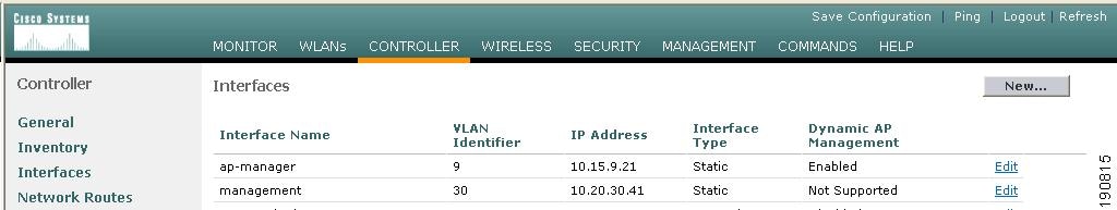
Perform the following to define and configure an interface to support guest traffic:
Step 1
Step 2
Figure 12-11 Interfaces
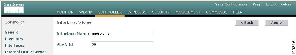
Defining an Interface Name and VLAN ID
Step 3
Figure 12-12 Interface Name and VLAN ID
Defining Interface Properties
Step 4
•
•
•
•
See Figure 12-13.
Figure 12-13 Defining Properties
Note
Anchor Controller DHCP Configuration (Optional)
If the anchor controller is going to manage DHCP services for the guest access WLAN, proceed with the following steps.
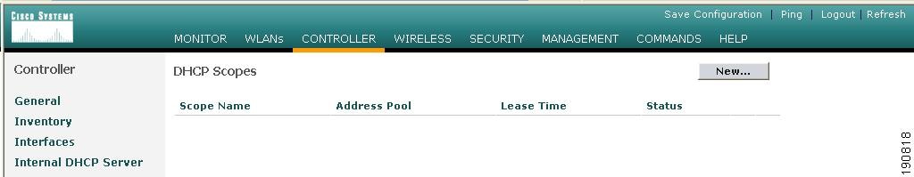
Adding a New DHCP Scope to the Anchor Controller
Step 1
Step 2
Step 3
Figure 12-14 Adding a New DHCP Scope
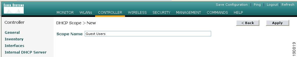
Defining a Scope Name
Step 4
Figure 12-15 Defining a Scope Name
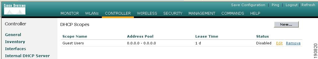
Step 5
Figure 12-16 Editing Scope Name
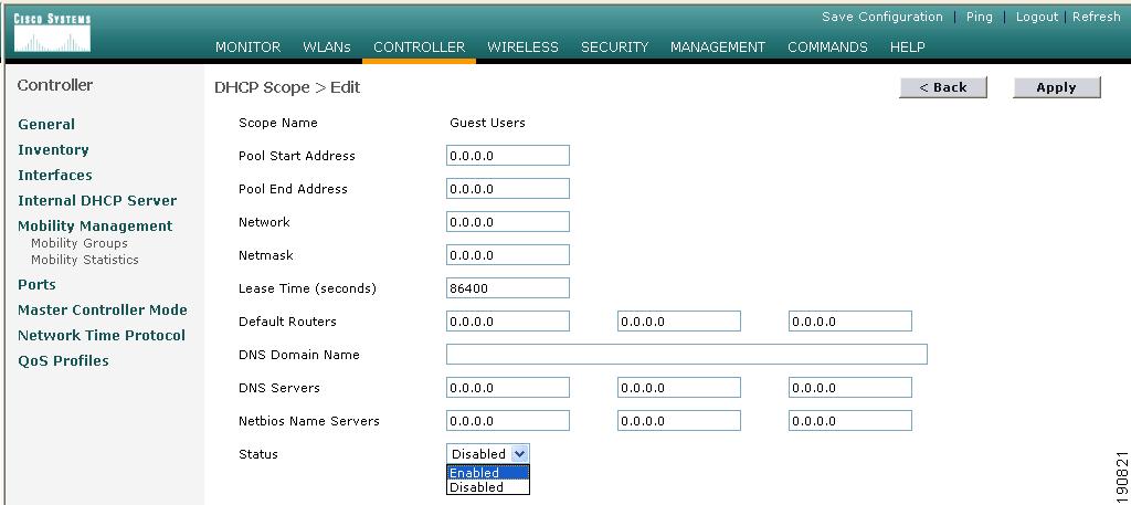
Defining Scope Properties
Step 6
•
•
•
•
•
Step 7
Figure 12-17 Enabling Scope Properties
Mobility Group Configuration
The following mobility group parameters should already be defined on the remote controllers as part of a standard centralized WLAN deployment. The anchor controller can also be configured with a mobility domain name, but it is not required to support termination of guest WLAN EoIP tunnels.
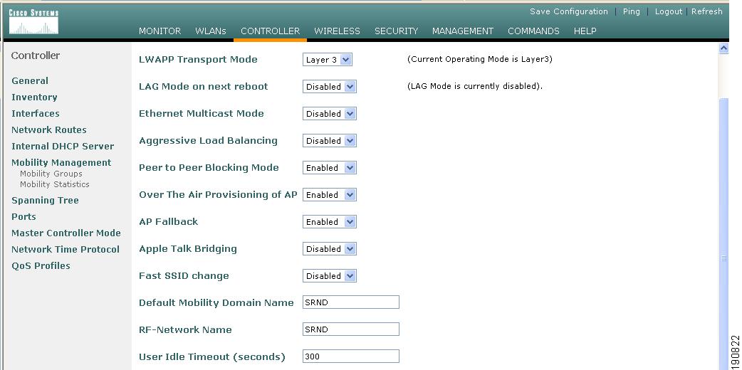
Defining a Default Mobility Domain Name for the Anchor Controller (Optional)
Assign a default mobility domain name for the anchor controller.
Step 1
Step 2
Step 3
Figure 12-18 Defining a Default Mobility Domain Name
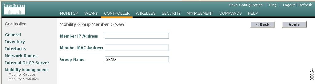
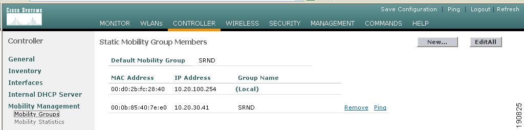
Defining Mobility Group Members for the Anchor Controller
Each campus (foreign) controller in the enterprise that will support the guest WLAN must be defined as a mobility group member in the anchor controller.
Step 1
Step 2
Figure 12-19 Defining Mobility Group Members
Adding Remote Controllers as Mobility Group Members
Step 3
Figure 12-20 Adding Remote Controllers
Adding an Anchor Controller as a Mobility Group Member in the Remote Controller
As described in WLAN Anchors and Ethernet in IP to Support Guest Access, each remote controller maps the guest WLAN into an EoIP tunnel that terminates on the anchor controller. Therefore, the anchor controller must be added as a member of the mobility group in each remote controller.
Step 1
Step 2
Figure 12-21 Adding an Anchor Controller
Guest WLAN Configuration
The following section describes how to configure a single guest WLAN. The guest WLAN is configured on each remote controller that manages APs where guest access is required.
Even though the anchor controller is not specifically used to manage lightweight APs, it must also be configured with the guest WLAN because the anchor controller represents an extension of the guest WLAN where user traffic is bridged (using LWAPP between the AP and the remote controller and EoIP between the remote controller and the anchor controller) to a physical interface and VLAN.
Note
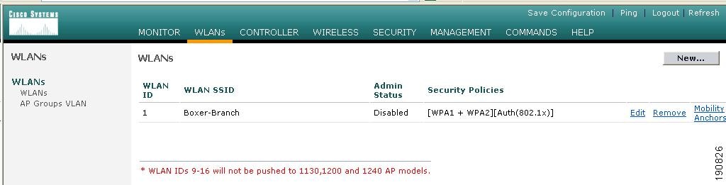
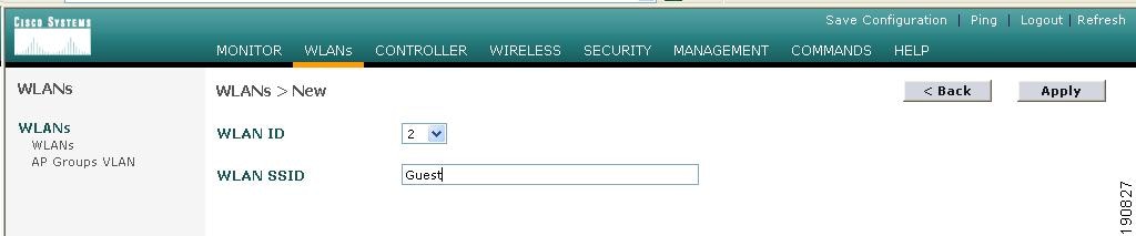
Guest WLAN Configuration for the Remote Controller
Step 1
Figure 12-22 Guest WLAN Configuration
Defining a Guest WLAN SSID
Step 2
The controller automatically assigns a VLAN ID. Administrators have the option selecting 1 - 16, as long as the ID is not already in use by another SSID/ WLAN.
Step 3
Figure 12-23 Defining a Guest WLAN SSID
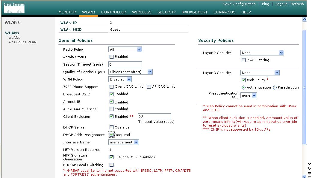
Defining Guest WLAN Policies
The following list represents typical parameter settings used for a guest WLAN:
Step 1
Step 2
•
•
Anything greater than 0 forces de-authentication after expiration and requires the user to re-authenticate through web portal.
•
•
This value can be changed.
•
This forces client to use DHCP. Statically configured clients are not accepted.
•
Note
Step 3
Figure 12-24 Defining Guest WLAN Policies
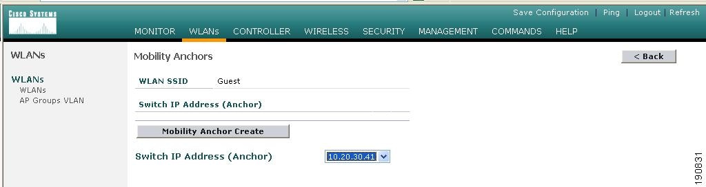
Defining the Guest WLAN Anchor
Step 1
Step 2
Figure 12-25 Defining Guest WLAN Anchors
A drop-down list of eligible controller IP addresses is displayed.
Selecting and Creating an Anchor
Step 3
Step 4
Figure 12-26 Selecting and Creating an Anchor
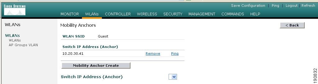
Verifying the Guest WLAN Mobility Anchor
The following screenshot shows a mobility anchor assigned to the guest WLAN. You can verify that it can be reached by clicking the Ping link as shown above.
Step 5
Figure 12-27 Verifying the Guest WLAN Mobility Anchor
Step 6
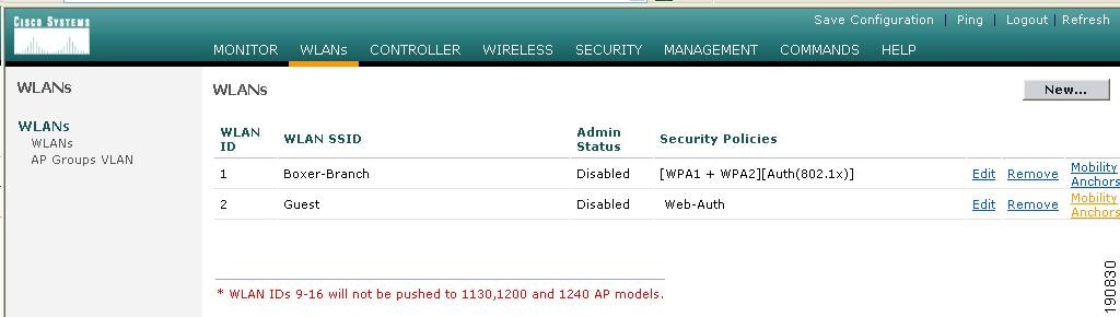
Enabling the Guest WLAN
Perform the following steps to enable the WLAN.
Step 1
Step 2
Step 3
Step 4
Figure 12-28 Enabling the Guest WLAN
This completes the guest WLAN configuration. Repeat all steps from Guest WLAN Configuration for the Remote Controller through Enabling the Guest WLAN for any additional remote controllers.
Guest WLAN Configuration on the Anchor Controller
Guest WLAN configuration on the anchor controller is identical to that performed on the remote controller except for minor differences in the WLAN policies configuration and mobility anchor definition. Repeat all steps from Guest WLAN Configuration for the Remote Controller through Enabling the Guest WLAN on the anchor controller.
Note
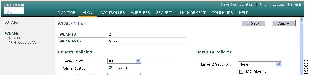
Guest WLAN Policies for the Anchor Controller
The policies defined for the guest WLAN on the anchor controller are the same except for the interface to which the WLAN is mapped. In this case, the guest WLAN is going to use the interface created in Guest VLAN Interface Configuration.
Step 1
Step 2
Step 3
Note
Step 4
Figure 12-29 Configuring Guest WLAN Policies
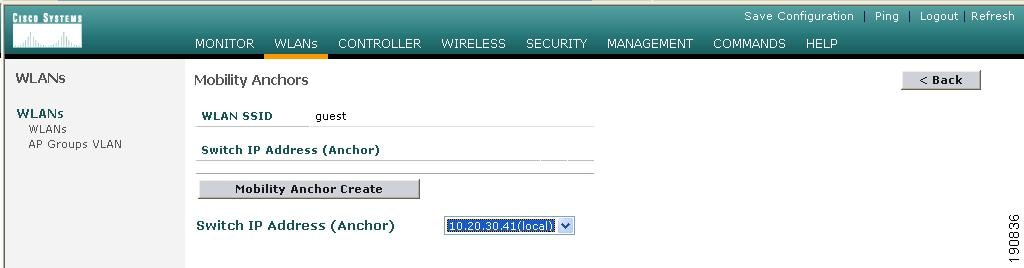
Defining the Guest WLAN Mobility Anchor
The mobility anchor that is used for the guest WLAN is the anchor controller itself.
Step 1
Step 2
Step 3
Step 4
Figure 12-30 Defining the Guest WLAN Mobility Anchor
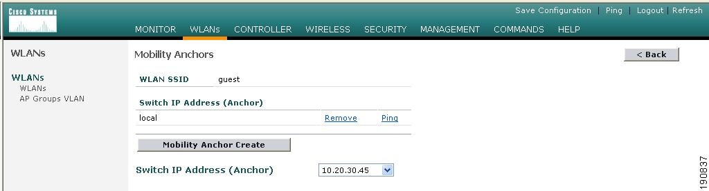
Note that the guest WLAN mobility anchor is local. (See Figure 12-31.)
Figure 12-31 Verifying Guest Mobility Anchor is local
Step 5
Web Portal Page Configuration and Management
The internal web server and associated functionality is hosted locally on the anchor controller. When a WLAN is configured to use a web policy, either for authentication or pass-through, the internal web server is invoked by default. No further configuration is required. The internal portal includes a few optional configuration parameters.
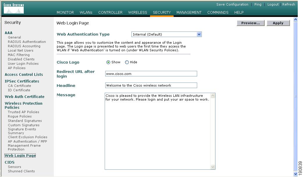
Internal Web Page Management
Step 1
Step 2
The configuration screen shown in Figure 12-32 is displayed. You can change the heading and message information that will appear on the portal page. You can also choose a post authentication redirect URL.
Figure 12-32 Configuration Screen
Step 3
Step 4
Importing A Web Page
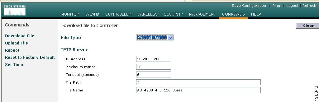
If you want a customized web page, one can be downloaded and stored locally on the anchor controller. To import a customized web page, perform the following steps:
Step 1
Figure 12-33 Importing a Web Page
Step 2
Step 3
Step 4
There are some caveats to be aware of with regard to downloading a web auth bundle:
•
•
•
•
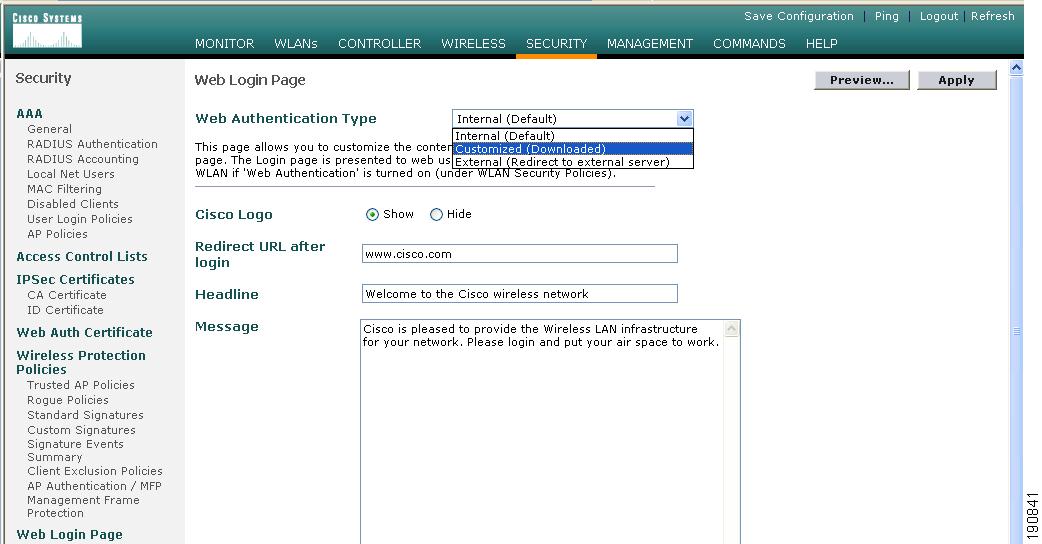
Selecting an Imported Web Auth Page
To use a customized web auth page that has been downloaded to the controller, perform the following:
Step 1
Step 2
Step 3
Step 4
Step 5
Figure 12-34 Selecting an Imported Web Auth Page
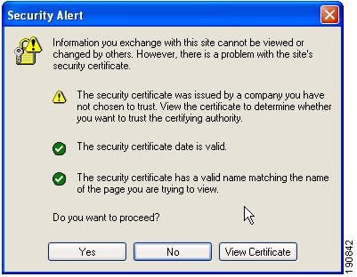
Internal Web Certificate Management
The web auth login page uses SSL for safeguarding user credentials. For simplicity, the controller uses a self-signed certificate. Because the certificate is self-signed, guest users can expect to see a pop-up alert similar to the following when they are redirected to the authentication page shown in Figure 12-35.
Figure 12-35 Authentication Page
At this point, the user can proceed by either clicking Yes or they can choose View Certificate and manually install it as a trusted site.
The web server uses the virtual interface IP address configured inAnchor Controller Interface Configuration as its source address. If a host name is defined along with the IP address, that host name must be resolvable by DNS so that:
•
•
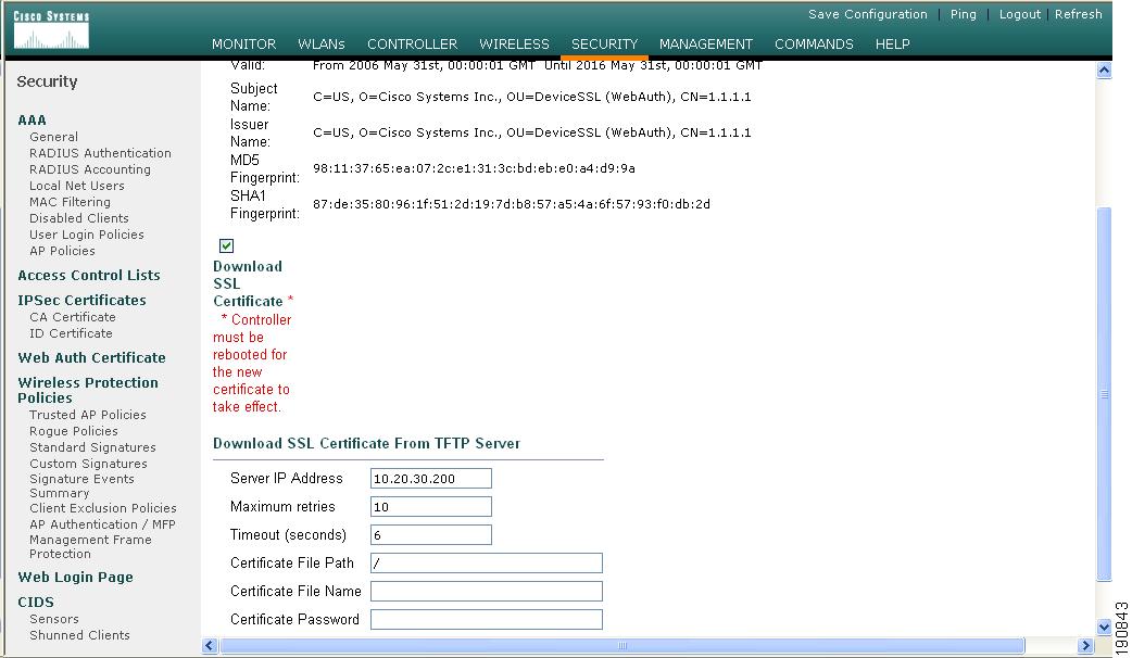
Importing an External Web Certificate
In those cases where a legitimate web certificate issued by a trusted root CA is required, one can be downloaded to the controller by performing the following:
Step 1
Step 2
Figure 12-36 Importing an External Web Certificate
Step 3
Step 4
Step 5
Step 6
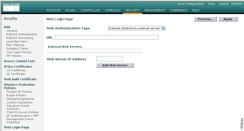
Support for External Web Redirection
In some cases, an enterprise might already have deployed a web portal system to support wired guest access or NAC functionality. If this is the case, the anchor controller can be configured to redirect wireless guest users to an external web portal:
Step 1
Step 2
Figure 12-37 Supporting External Web Redirection
Step 3
Step 4
Guest Management
If guest credentials are going to be stored locally on the anchor controller, there are two methods by which they can be created and posted to the controller:
•
•
Guest Management Using WCS
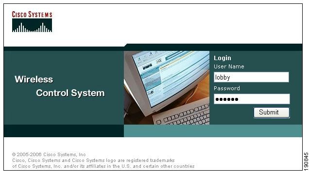
The following configuration examples assume WCS version 4.0 has been installed, configured, and a lobby ambassador account has been established. See Chapter 8, "Cisco Unified Wireless Control System," for more information on installing and configuring WCS.
Step 1
Figure 12-38 Using WCS
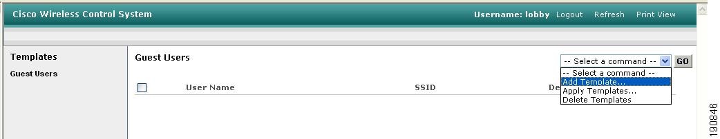
After logging in, the screen shown in Figure 12-39 is displayed.
Figure 12-39 Adding a Template
Step 2
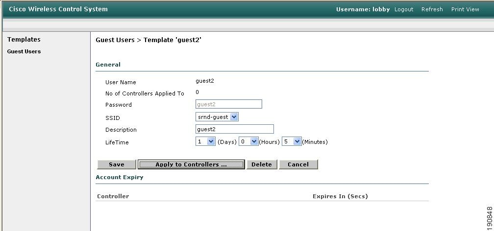
The screen shown in Figure 12-40 appears.
Figure 12-40 Guest User Template
Step 3
Step 4
Step 5
Step 6
Step 7
Applying Credentials
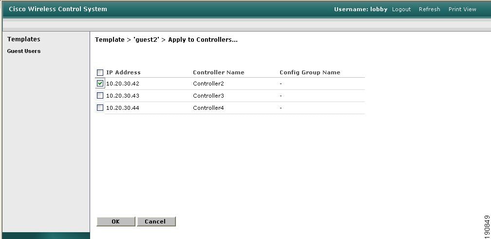
After the credentials have been created, the screen shown in Figure 12-41 offers the option to apply them to one or more controllers.
Figure 12-41 Applying Credentials
Step 1
As shown in Figure 12-42, a list of eligible controllers is displayed (only those controllers that have been configured with the guest WLAN are displayed).
Figure 12-42 Apply to Controllers Screen
Note
Step 2
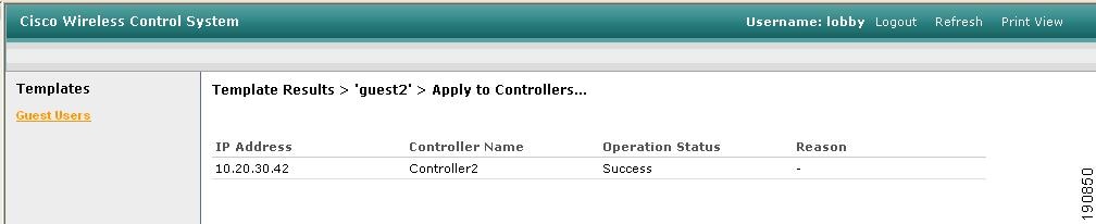
A confirmation page that verifies that the user credentials were saved to the anchor controller is displayed. (See Figure 12-43.)
Figure 12-43 Confirmation Page
Step 3
Figure 12-44 Summary Page
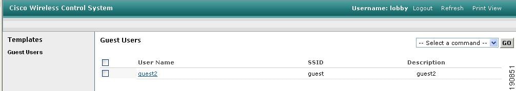
Step 4
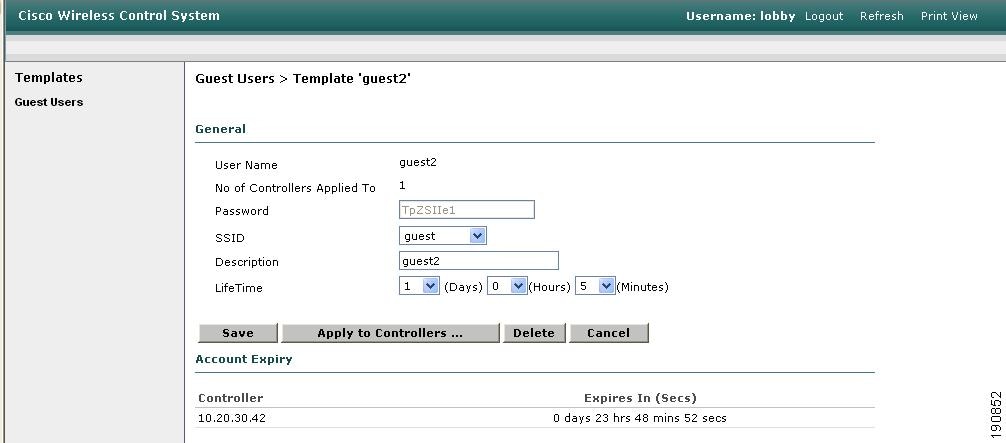
The user template is displayed, as shown in Figure 12-45.
Figure 12-45 Editing Guest Credentials
In this page, you can make the following modifications if desired:
•
•
•
•
•
Note
Managing Guest Credentials Directly on the Anchor Controller
The following procedure assumes a network administrator has established a Local Management User account with Lobby Admin privileges on the controller.
Step 1
After login, the screen shown in Figure 12-46is displayed.
Figure 12-46 Anchor Controller Login
Step 2
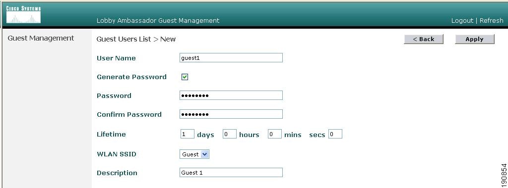
The screen shown in Figure 12-47 appears.
Figure 12-47 Creating User Credentials
Step 3
a.
b.
c.
d.
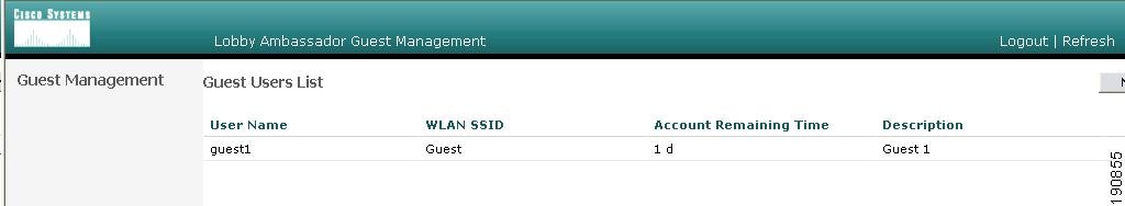
Step 4
The screen shown in Figure 12-48 appears and shows the newly added guest user.
Figure 12-48 Guest Users List
From this screen you have the option to do the following:
•
•
•
Configuring the Maximum Number of User Accounts
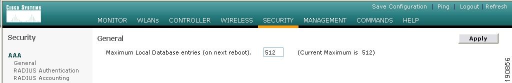
The default number of guest user accounts that can be defined on the controller is 512. This value can be changed by completing the following steps.
Step 1
Figure 12-49 Configuring the Maximum Number of User Accounts
Step 2
Step 3
Step 4
Guest User Management Caveats
•
•
•
•
External Radius Authentication
As described in Guest User Authentication, an external RADIUS server can be used to authenticate guest users in place of creating and storing guest credentials locally on the anchor controller. If this method is used, then the lobby admin features described in Guest Management cannot be used. It is assumed that some other guest management system will be used in conjunction with the external RADIUS server.
To configure a guest WLAN to use an external RADIUS server, perform the following configuration steps on the anchor controller.
Adding a RADIUS Server
Step 1
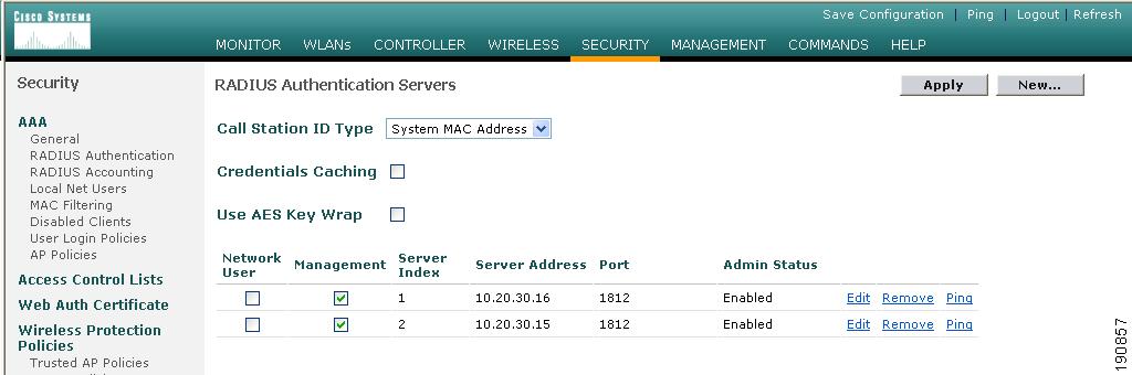
A summary screen is displayed. (See Figure 12-50.)
Figure 12-50 Summary Screen
Step 2
The screen shown in Figure 12-51appears.
Figure 12-51 Defining RADIUS Server Settings
Step 3
If the Network User check box is cleared, the RADIUS server is used only for user authentication when it is specifically selected under a given WLANs RADIUS setting. Otherwise, if the check box is checked, the server is used globally for all user authentications based on its server priority.
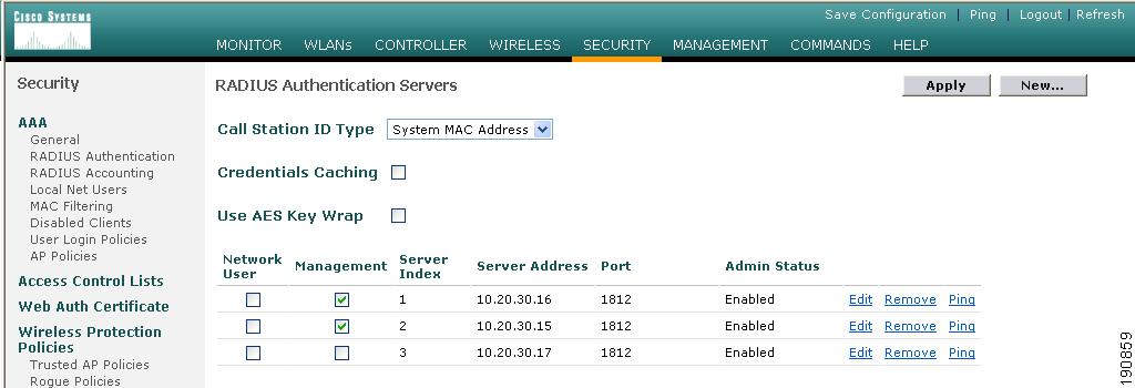
Step 4
The summary screen shows the newly added server. (See Figure 12-52.)
Figure 12-52 Summary Screen
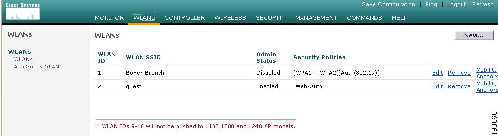
Step 5
Step 6
Figure 12-53 WLANs Tab
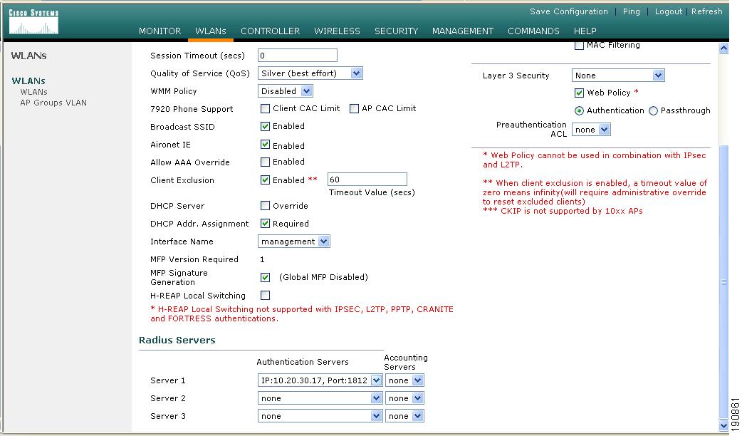
Step 7
The guest WLAN configuration screen is displayed, as shown in Figure 12-54.
Figure 12-54 Guest WLAN Configuration Screen
Step 8
External Access Control
The centralized guest access topology described in this chapter can be integrated with an external access control platform such as BBSM or Clean Access.
In this scenario, an enterprise might have already deployed an access control platform in their Internet DMZ to support wired guest access services (see Figure 12-55).
Figure 12-55 Wireless Guest Access with External Access Control
l
As shown in Figure 12-55, The wireless guest access topology remains the same except the guest VLAN interface on the anchor controller, instead of connecting to a firewall or border router, connects to an inside interface on an access control platform such as BBSM.
In this scenario, the BBSM platform is responsible for redirection, web authentication and subsequent access to the Internet. The campus and anchor controllers are only used to tunnel guest WLAN traffic across the enterprise into the DMZ where BBSM or some other platform is used to manage guest access.
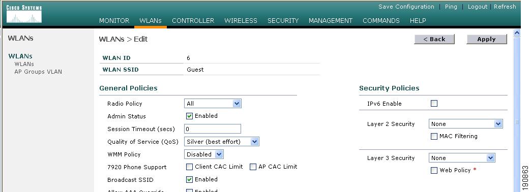
Configuration of the guest WLAN, campus and anchor controllers is the same as described in the previous examples. The only exception is that web policy is disabled under the guest WLANs security policy (see Figure 12-56).
Figure 12-56 Guest WLAN Security Policy
The configuration above establishes a WLAN with no security policies. Guest traffic passes through the anchor controller to the inside or untrusted interface of BBSM or Cisco Clean Access Server, where it is blocked until a user has authenticated.
DHCP can be hosted locally on the controller or externally via BBSM or dedicated server.
Its beyond the scope of this chapter to address BBSM or other external platform specific configuration. See the platform documentation for additional configuration guidelines.
Verifying Guest Access Functionality
The guest access service is working correctly if a user:
•
•
•
•
Troubleshooting Guest Access
The following verifications and troubleshooting tasks assume:
•
•
Before attempting to troubleshoot the various symptoms below, at the very least you should be able to ping from the campus (foreign) controller to the anchor controller. If not, verify routing.
Next, you should be able to perform the following advanced pings. These can only be performed via the serial console interfaces of the controllers:
•
This pings the neighbor controller through the LWAPP control channel.
•
This pings the neighbor controller through the LWAPP data channel.
If pings go through, but mpings do not, ensure that each WLCs mobility group name is the same and ensure that each WLCs IP, MAC, and mobility group name is entered in every WLC mobility list.
If pings and mpings are successful, but epings are not, check the network to make sure that IP protocol 97 (Ethernet-over-IP) is not being blocked.
User Cannot Associate to the Guest WLAN
•
•
•
User Does Not Obtain an IP Address via DHCP
•
•
•
–
–
–
–
–
–
User is Not Redirected to Web Auth Page
The following assumes the user is able to associate to the guest WLAN and obtain an IP address
•
•
•
•
Note
User Cannot Authenticate
•
–
•
User Cannot Connect to Internet or Upstream Service
•
•
System Monitoring
Following are some monitoring commands that might be helpful in troubleshooting.
Anchor Controller
From the serial console port:
(Cisco Controller) >show client summaryNumber of Clients................................ 1MAC Address AP Name Status WLAN Auth Protocol Port----------------- ----------------- ------------- ---- ---- -------- ----00:40:96:a6:d5:3a 10.20.100.254 Associated 6 Yes Mobile 1Note that the protocol is Mobile. The Auth field reflects the actual status of the user. If the user has passed web auth, the field displays YES. If not, the field shows NO.
Also notice the AP name. This is the management IP address of the remote controller (originating controller).
From the summary information, use the client MAC to show more detail:
(Cisco Controller) >show client detail 00:40:96:a6:d5:3aClient MAC Address............................... 00:40:96:a6:d5:3aClient Username ................................. guest1AP MAC Address................................... 00:00:00:00:00:00Client State..................................... AssociatedWireless LAN Id.................................. 6BSSID............................................ 00:00:00:00:00:05Channel.......................................... N/AIP Address....................................... 10.20.31.101Association Id................................... 0Authentication Algorithm......................... Open SystemReason Code...................................... 0Status Code...................................... 0Session Timeout.................................. 0Client CCX version............................... No CCX supportRe-Authentication Timeout........................ 81586Remaining Re-Authentication Time................. 79010Mirroring........................................ DisabledQoS Level........................................ SilverDiff Serv Code Point (DSCP)...................... disabled802.1P Priority Tag.............................. disabledWMM Support...................................... DisabledMobility State................................... Export AnchorMobility Foreign IP Address...................... 10.20.100.254 <Remote ControllerMobility Move Count.............................. 1Security Policy Completed........................ YesPolicy Manager State............................. RUNPolicy Manager Rule Created...................... YesNPU Fast Fast Notified........................... YesPolicy Type...................................... N/AEncryption Cipher................................ NoneEAP Type......................................... UnknownInterface........................................ wlan-intVLAN............................................. 31Client Capabilities:CF Pollable................................ Not implementedCF Poll Request............................ Not implementedShort Preamble............................. Not implementedPBCC....................................... Not implementedChannel Agility............................ Not implementedListen Interval............................ 0Client Statistics:Number of Bytes Received................... 0Number of Bytes Sent....................... 0Number of Packets Received................. 0Number of Packets Sent..................... 0Number of Policy Errors.................... 0Radio Signal Strength Indicator............ UnavailableSignal to Noise Ratio...................... UnavailableNearby AP Statistics:TxExcessiveRetries: 0TxRetries: 0RtsSuccessCnt: 0RtsFailCnt: 0TxFiltered: 0TxRateProfile: [0,0,0,0,0,0,0,0,0,0,0,0]The same information can be obtained through the web configuration and management interface of the controller under Client Detail. (See Figure 12-57.)
Figure 12-57 Monitor > Client Detail
Campus (Foreign) Controller
From the serial console port:
(Cisco Controller) >show client summaryNumber of Clients................................ 1MAC Address AP Name Status WLAN Auth Protocol Port----------------- ----------------- ------------- ---- ---- -------- ----00:40:96:a6:d5:3a Branch:24:a6:50 Associated 2 Yes 802.11g 1Note that the protocol field is 802.11g, whereas the protocol field on the anchor controller for the same client is mobile. The campus (foreign) controller always shows the user as authenticated and the AP name reflects the actual AP to which the client is associated.
Additional details can be obtained using the following:
Cisco Controller) >show client detail 00:40:96:a6:d5:3aClient MAC Address............................... 00:40:96:a6:d5:3aClient Username ................................. N/AAP MAC Address................................... 00:0b:85:24:a6:50Client State..................................... AssociatedWireless LAN Id.................................. 2BSSID............................................ 00:0b:85:24:a6:5eChannel.......................................... 1IP Address....................................... UnknownAssociation Id................................... 4Authentication Algorithm......................... Open SystemReason Code...................................... 0Status Code...................................... 0Session Timeout.................................. 0Client CCX version............................... No CCX supportRe-Authentication Timeout........................ 0Remaining Re-Authentication Time................. Timer is not runningQoS Level........................................ SilverDiff Serv Code Point (DSCP)...................... disabled802.1P Priority Tag.............................. disabledWMM Support...................................... DisabledMobility State................................... Export ForeignMobility Anchor IP Address....................... 10.20.30.41 <anchor controller>Mobility Move Count.............................. 0Security Policy Completed........................ YesPolicy Manager State............................. RUNPolicy Manager Rule Created...................... YesPolicy Type...................................... N/AEncryption Cipher................................ NoneEAP Type......................................... UnknownInterface........................................ management <source of EoIP Tunnel>VLAN............................................. 0Client Capabilities:CF Pollable................................ Not implementedCF Poll Request............................ Not implementedShort Preamble............................. ImplementedPBCC....................................... Not implementedChannel Agility............................ Not implementedListen Interval............................ 0Client Statistics:Number of Bytes Received................... 83288Number of Bytes Sent....................... 310361Number of Packets Received................. 670Number of Packets Sent..................... 430Number of Policy Errors.................... 0Radio Signal Strength Indicator............ -30 dBmSignal to Noise Ratio...................... 62 dBNearby AP Statistics:TxExcessiveRetries: 0TxRetries: 0RtsSuccessCnt: 0RtsFailCnt: 0TxFiltered: 0TxRateProfile: [0,0,0,0,0,0,0,0,0,0,0,0]Branch:24:a6:50(slot 1) ...................antenna0: 451 seconds ago -26 dBm................ antenna1: 1522 seconds ago -68 dBmThe same information can be obtained through the controller web configuration and management interface under client detail (see Figure 12-57).
Debug Commands
Additional debug commands that might be used from the serial console include the following:
debug mac addr <client mac address>debug mobility handoff enabledebug mobility directory enabledebug dhcp packet enabledebug pem state enabledebug pem events enabledebug dot11 mobile enabledebug dot11 state enable