Table Of Contents
Microsoft Exchange 2010 with VMware VSphere on Cisco Unified Computing System with NetApp Storage
Exchange 2010 Deployment Scenario
Global Site Selector (GSS) and Application Control Engine (ACE)
Load Balancing for an Exchange 2010 Environment
Exchange 2010 MAPI Client Load Balancing Requirements
Configuring Static Port Mapping For RPC-Based Services
Exchange 2010 Outlook Web Access Load Balancing Requirements
Outlook Anywhere Load Balancing Requirements
Cisco Application Control Engine Overview
Cisco Unified Computing System Hardware
Cisco UCS 2100 Series Fabric Extenders
UCS 6100 XP Series Fabric Interconnect
Programmatically Deploying Server Resources
Dynamic Provisioning with Service Profiles
NAM Appliance for Virtual Network Monitoring
NetApp Storage Technologies and Benefits
NetApp Strategy for Storage Efficiency
Cisco Wide Area Application Services for Branch Users
Advanced Compression Using DRE and LZ Compression
Messaging Application Programming Interface (MAPI) Protocol Acceleration
Secure Socket Layer (SSL) Protocol Acceleration
Advanced Data Transfer Compression
Application-Specific Acceleration
Solution Design and Deployment
Exchange 2010 Design Considerations
Processor Cores—Factors to Consider
Microsoft Exchange 2010 Calculator
Configuring CPU and Memory on Exchange VMs
M81KR (Palo) Network Interface
Nexus 1000V and Virtual Machine Networking
NAM Reporting of ERSPAN from Nexus 1000V
Storage Configuration for Exchange 2010
NetApp RAID-DP Storage Calculator for Exchange 2010
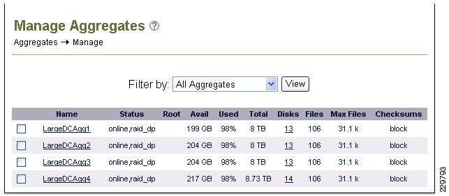
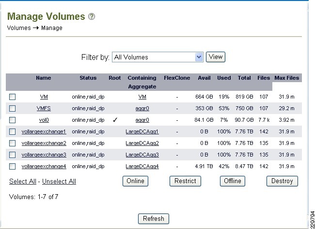
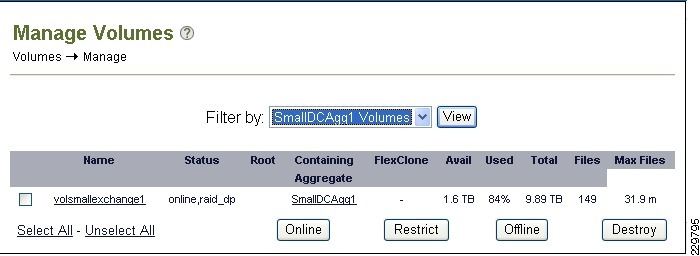
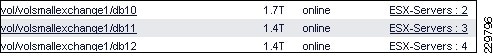
Aggregate, Volume, and LUN Sizing
NetApp Best Practices for Exchange 2010
VSphere Virtualization Best Practices for Exchange 2010
Memory Configuration Guidelines
Networking Configuration Guidelines
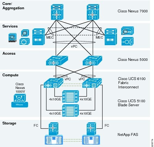
Data Center Network Architecture
Global Site Selector Configuration for Site Failover
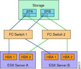
Fibre-Channel Storage Area Network
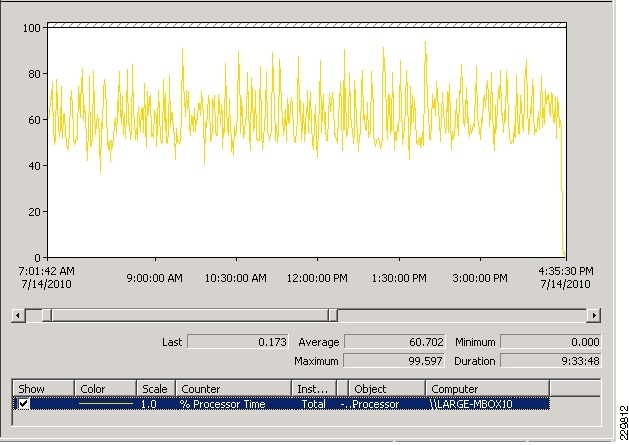
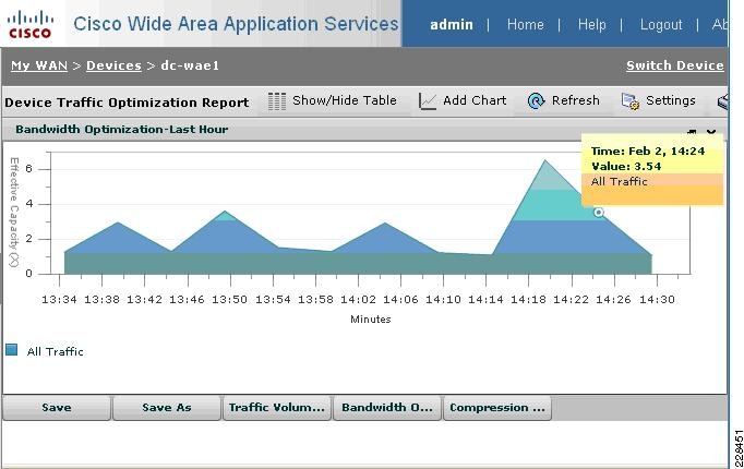
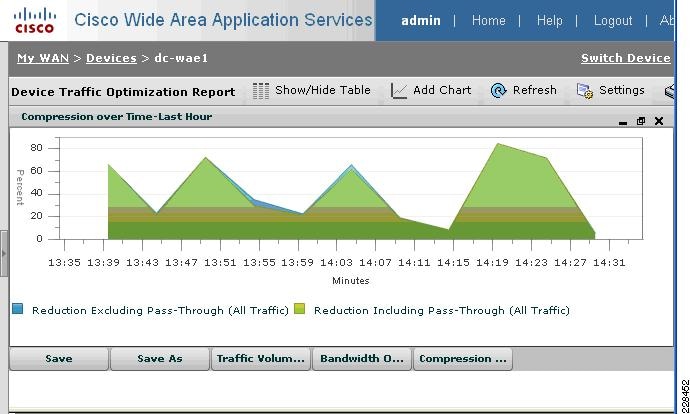
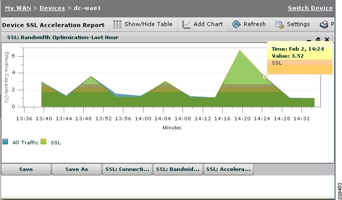
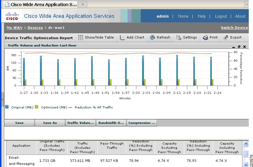
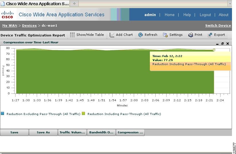
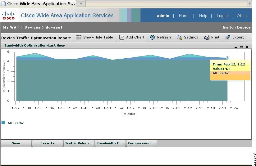
Validating Exchange Server Performance
WAAS Setup Between Branch and Data Center
WAAS Setup for Remote User to Data Center
Appendix—ACE Exchange Context Configuration
About Cisco Validated Design (CVD) Program
Microsoft Exchange 2010 with VMware VSphere on Cisco Unified Computing System with
NetApp StorageLast Updated: February 7, 2011
Building Architectures to Solve Business Problems
About the Authors
Karen Chan, Solutions Architect, Systems Architecture and Strategy, Cisco SystemsKaren is currently a Solutions Architect in Cisco Systems Architecture and Strategy group. Prior to this role, she was an Education Architect in the Industry Solutions Engineering team at Cisco. She has also worked as a technical marketing engineer in the Retail group on the Cisco PCI for Retail solution as well as in the Financial Services group on the Cisco Digital Image Management solution. Prior to Cisco, she spent 11 years in software development and testing, including leading various test teams at Citrix Systems, Orbital Data, and Packeteer, to validate software and hardware functions on their WAN optimization and application acceleration products. She holds a bachelor of science in electrical engineering and computer science from the University of California, Berkeley.
Alex Fontana, Technical Solutions Architect, VMwareAlex Fontana is a Technical Solutions Architect at VMware, with a focus on virtualizing Microsoft tier-1 applications. Alex has worked in the information technology industry for over 10 years during which time five years have been spent designing and deploying Microsoft applications on VMware technologies. Alex specializes in Microsoft operating systems and applications with a focus on Active Directory, Exchange, and VMware vSphere. Alex is VMware, Microsoft, and ITIL certified.
Robert Quimbey, Microsoft Alliance Engineer, NetAppRobert joined NetApp in 2007 after nearly 9 years as a member of the Microsoft Exchange product team, where he was responsible for storage and high availability. Since joining NetApp, his activities have continued to center around Exchange, including designing sizing tools, best practices, and reference architectures.
Microsoft Exchange 2010 with VMware VSphere on Cisco Unified Computing System with NetApp Storage
Introduction
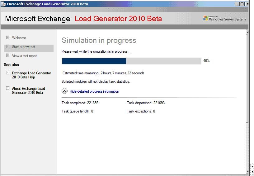
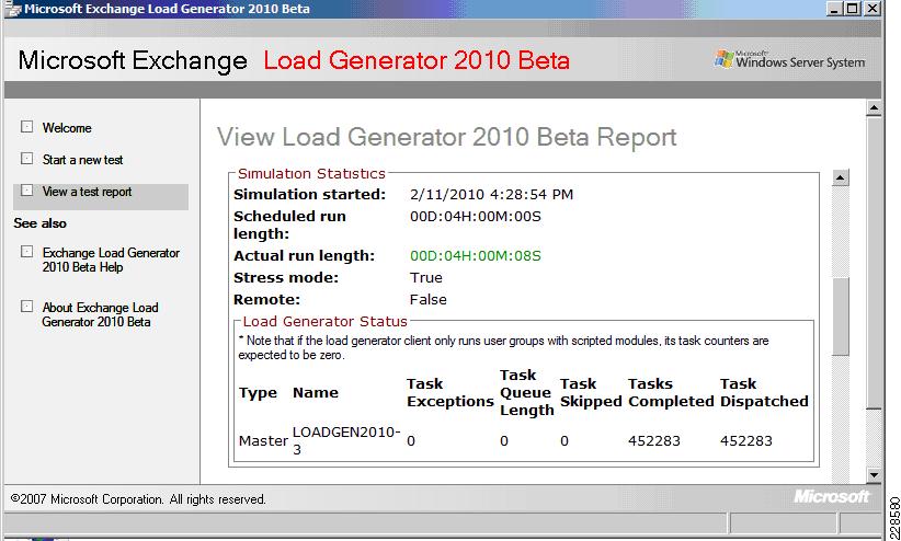
This design and deployment guide demonstrates how enterprises can apply best practices for VSphere 4.0, Microsoft Exchange 2010, and NetApp Fiber-Attached Storage arrays to run virtualized and native installations of Exchange 2010 servers on the Cisco® Unified Computing System™ (UCS). VSphere and Exchange 2010 are deployed in a Cisco Data Center Business Advantage architecture that provides redundancy/high availability, network virtualization, network monitoring, and application services. The Cisco Nexus 1000V virtual switch is deployed as part of the VSphere infrastructure and integrated with the Cisco Network Analysis Module appliance to provide visibility and monitoring into the virtual server farm. This solution was validated within a multi-site data center scenario with a realistically-sized Exchange deployment using Microsoft's Exchange 2010 Load Generator tool to simulate realistic user loads. The goal of the validation was to verify that the Cisco UCS, NetApp storage, and network link sizing was sufficient to accommodate the LoadGen user workloads. Cisco Global Site Selector (GSS) provides site failover in this multi-site Exchange environment by communicating securely and optimally with the Cisco ACE load balancer to determine application server health. User connections from branch office and remote sites are optimized across the WAN with Cisco Wide Area Application Services (WAAS).
Audience
This document is primarily intended for enterprises interested in virtualizing their Exchange 2010 servers using VMware VSphere on the Cisco Unified Computing System. These enterprises would be planning to use Netapp FAS for storage of their virtual machines and Exchange mailboxes. This design guide also applies to those who want to understand how they can optimize application delivery to the end user through a combination of server load balancing and WAN optimization.
Solution Overview
This solution provides an end-to-end architecture with Cisco, VMware, Microsoft, and NetApp technologies that demonstrates how Microsoft Exchange 2010 servers can be virtualized to support around 10,000 user mailboxes and to provide high availability and redundancy for server and site failover. The design and deployment guidance cover the following solution components:
•
Exchange 2010 application
•
•
•
•
•
•
•
•
Exchange 2010 Deployment Scenario
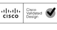
This solution involves a multi-site data center deployment—a large data center, a small data center, and a data center for site disaster recovery geographically located between the large and the small data centers. The servers in the disaster recovery data center are all passive under normal operations. The large data center has two Mailbox servers, two Hub Transport servers, two Client Access Servers, and two Active Directory/DNS servers—all in an active-active configuration. A single server failure of any role causes failover to the secondary server in the local site. For a dual-server failure or local site failure, failover to the disaster recovery data center servers occurs. The small data center has one Exchange server that contains the Mailbox server, Hub Transport, and Client Access roles and it also has one Active Directory/DNS server. In the event of any single server failure or a local site failure, failover to the servers in the disaster recovery site occurs.
The server assignments to the UCS blade servers in the large data center are:
•
•
–
–
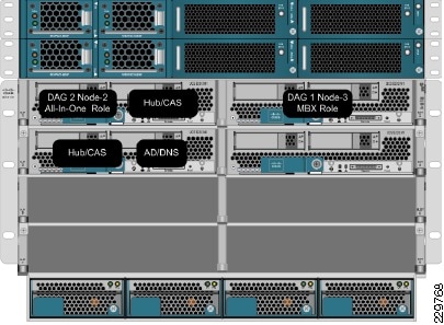
Figure 1 illustrates the assignment of the application servers to the UCS blades in the large data center.
Figure 1 Application Servers Assigned to UCS Blade in Large Data Center
The server assignments to the UCS blade servers in the small data center are:
•
•
Figure 2 Application Server VMs Assigned to UCS Blade in Small Data Center
The server assignments to the UCS blade servers in the disaster recovery data center are:
•
•
Global Site Selector (GSS) and Application Control Engine (ACE)
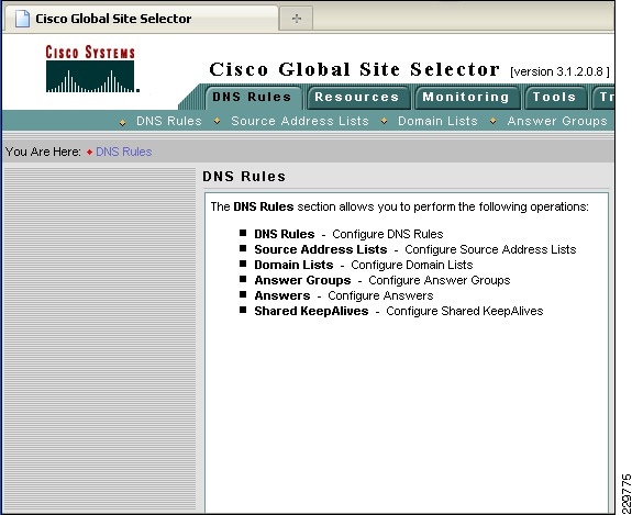
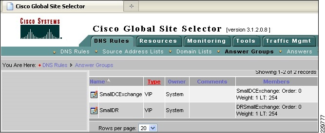
The Cisco Global Site Selector appliance is used in this solution to redirect incoming Exchange client requests to the appropriate data center servers, depending on the failover scenario. The Cisco GSS traffic management process continuously monitors the load and health of a device (such as the ACE or a particular server) within each data center. The Cisco GSS uses this information in conjunction with customer-controlled load balancing algorithms to select, in real time, the best data center or server destinations that are available and not overloaded per user-definable load conditions. In this manner, the Cisco GSS intelligently selects best destination to ensure application availability and performance for any device that uses common DNS request for access.
While the Cisco GSS can monitor health and performance of almost any server or load balancing/application delivery device using ICMP, TCP, HTTP-header, and SNMP probes, when used with the ACE load balancer, it has enhanced monitoring capabilities. To retrieve more granular monitoring data that is securely transmitted in a timely manner, the Cisco GSS can make use of the special KAL-AP monitoring interface built into the Cisco Application Control Engine (ACE) Modules and Cisco ACE 4710 appliances. For users this means:
•
•
For IT operators this means the Cisco GSS adds agility by automating reactions to changes in local and global networks to ensure application availability and performance. If a network outage occurs, the Cisco GSS can automatically or under administrative control direct clients to a disaster recovery site within seconds. The Cisco GSS also adds security and intelligence to the DNS process by offering cluster resiliency that can be managed as a single entity.
The following describes how the GSS combined with the ACE can intelligently route incoming Exchange client requests to the data center and Exchange server that is the most suitable based on availability and server load:
1.
2.
3.
–
–
–
–
4.
Table 3 shows the different protocols and ports used by the GSS appliance.
Table 3 GSS Service Ports
20-23
TCP
FTP, SSH, and Telnet server services on the GSS
20-23
Any
TCP
Return traffic of FTP and Telnet GSS CLI commands
Any
53
UDP, TCP
GSS DNS server traffic
53
UDP
GSS software reverse lookup and "dnslookup" queries
123
123
UDP
Network Time Protocol (NTP) updates
161
UDP
Simple Network Management Protocol (SNMP) traffic
Any
443
TCP
Primary GSSM GUI
13043
1304
UDP
CRA keepalives
Any
2000
UDP
Inter-GSS periodic status reporting
Any
2001-2005
TCP
Inter-GSS communication
2001-2005
Any
TCP
Inter-GSS communication
Any
3002-3008
TCP
Inter-GSS communication
3002-3008
Any
TCP
Inter-GSS communication
3340
Any
TCP
Sticky and Config Agent communication
3341
Any
TCP
Sticky communication source
3342
Any
TCP
Sticky and DNS processes communication
50022
Any
UDP
KAL-AP keepalives
19743
1974
UDP
DRP protocol traffic
Any
5001
TCP
Global sticky mesh protocol traffic
5001
Any
TCP
Global sticky mesh protocol traffic
1 http://www.cisco.com/en/US/docs/app_ntwk_services/data_center_app_services/gss4400series/v3.1.1/administration/guide/ACLs.html#wp999192
2 For communication between ACE and GSS.
3 For communication between GSS and other network device (neither ACE nor GSS).
3 Note: Line items in Table 3 not marked with footnotes 2 or 3 are for communications involving one or more GSS devices.
Exchange 2010 Servers
This solution involved implementing the following three Exchange 2010 server roles as VMware VSphere virtual machines and physical servers on the Cisco UCS:
•
•
•
Since the Edge Transport role is an optional role for an Exchange deployment, it was not included in this solution. For guidance on deploying an Edge Transport server in a Data Center Business Advantage Architecture with ACE load balancing, see the following Cisco design guide: http://www.cisco.com/en/US/docs/solutions/Verticals/mstdcmsftex.html#wp623892.
Hub Transport Server Role
For those familiar with earlier versions of Exchange Server 2007, the Hub Transport server role replaces what was formerly known as the bridgehead server in Exchange Server 2003. The function of the Hub Transport server is to intelligently route messages within an Exchange Server 2010 environment. By default, SMTP transport is very inefficient at routing messages to multiple recipients because it takes a message and sends multiple copies throughout an organization. As an example, if a message with a 5-MB attachment is sent to 10 recipients in an SMTP network, typically at the sendmail routing server, the 10 recipients are identified from the directory, and 10 individual 5-MB messages are transmitted from the sendmail server to the mail recipients, even if all of the recipients' mailboxes reside on a single server.
The Hub Transport server takes a message destined to multiple recipients, identifies the most efficient route to send the message, and keeps the message intact for multiple recipients to the most appropriate endpoint. So, if all of the recipients are on a single server in a remote location, only one copy of the 5-MB message is transmitted to the remote server. At that server, the message is then broken apart with a copy of the message dropped into each of the recipient's mailboxes at the endpoint.
The Hub Transport server in Exchange Server 2010 does more than just intelligent bridgehead routing, though; it also acts as the policy compliance management server. Policies can be configured in Exchange Server 2010 so that after a message is filtered for spam and viruses, the message goes to the policy server to be assessed whether the message meets or fits into any regulated message policy and appropriate actions are taken. The same is true for outbound messages; the messages go to the policy server, the content of the message is analyzed, and if the message is determined to meet specific message policy criteria, the message can be routed unchanged or the message can be held or modified based on the policy. As an example, an organization might want any communications referencing a specific product code name, or a message that has content that looks like private health information, such as Social Security number, date of birth, or health records of an individual, to be held or encryption to be enforced on the message before it continues its route.
Client Access Server Role
The Client Access Server role in Exchange Server 2010 (as was also the case in Exchange Server 2007) performs many of the tasks that were formerly performed by the Exchange Server 2003 front-end server, such as providing a connecting point for client systems. A client system can be an Office Outlook client, a Windows Mobile handheld device, a connecting point for OWA, or a remote laptop user using Outlook Anywhere to perform an encrypted synchronization of their mailbox content.
Unlike a front-end server in Exchange Server 2003 that effectively just passed user communications on to the back-end Mailbox server, the CAS does intelligent assessment of where a user's mailbox resides and then provides the appropriate access and connectivity. This is because Exchange Server 2010 now has replicated mailbox technology where a user's mailbox can be active on a different server in the event of a primary mailbox server failure. By allowing the CAS server to redirect the user to the appropriate destination, there is more flexibility in providing redundancy and recoverability of mailbox access in the event of a system failure.
Mailbox Server Role
The Mailbox server role is merely a server that holds users' mailbox information. It is the server that has the Exchange Server EDB databases. However, rather than just being a database server, the Exchange Server 2010 Mailbox server role can be configured to perform several functions that keep the mailbox data online and replicated. For organizations that want to create high availability for Exchange Server data, the Mailbox server role systems would likely be clustered and not just a local cluster with a shared drive (and, thus, a single point of failure on the data), but rather one that uses the new Exchange Server 2010 Database Availability Groups. The Database Availability Group allows the Exchange Server to replicate data transactions between Mailbox servers within a single data center site or across several data center sites. In the event of a primary Mailbox server failure, the secondary data source can be activated on a redundant server with a second copy of the data intact. Downtime and loss of data can be drastically minimized, if not completely eliminated, with the ability to replicate mailbox data in real-time.
Microsoft eliminated single copy clusters, Local Continuous Replication, Clustered Continuous Replication, and Standby Continuous Replication in Exchange 2010 and substituted in their place Database Availability Group (DAG) replication technology. The DAG is effectively CCR, but instead of a single active and single passive copy of the database, DAG provides up to 16 copies of the database and provides a staging failover of data from primary to replica copies of the mail. DAGs still use log shipping as the method of replication of information between servers. Log shipping means that the 1-MB log files that note the information written to an Exchange server are transferred to other servers and the logs are replayed on that server to build up the content of the replica system from data known to be accurate. If during a replication cycle a log file does not completely transfer to the remote system, individual log transactions are backed out of the replicated system and the information is re-sent. Unlike bit-level transfers of data between source and destination used in Storage Area Networks (SANs) or most other Exchange Server database replication solutions, if a system fails, bits do not transfer and Exchange Server has no idea what the bits were, what to request for a resend of data, or how to notify an administrator what file or content the bits referenced. Microsoft's implementation of log shipping provides organizations with a clean method of knowing what was replicated and what was not. In addition, log shipping is done with small 1-MB log files to reduce bandwidth consumption of Exchange Server 2010 replication traffic. Other uses of the DAG include staging the replication of data so that a third or fourth copy of the replica resides "offline" in a remote data center; instead of having the data center actively be a failover destination, the remote location can be used to simply be the point where data is backed up to tape or a location where data can be recovered if a catastrophic enterprise environment failure occurs.
A major architecture change with Exchange Server 2010 is how Outlook clients connect to Exchange Server. In previous versions of Exchange Server, even Exchange Server 2007, RPC/HTTP and RPC/HTTPS clients would initially connect to the Exchange Server front end or Client Access Server to reach the Mailbox servers, while internal MAPI clients would connect directly to their Mailbox Server. With Exchange Server 2010, all communications (initial connection and ongoing MAPI communications) go through the Client Access Server, regardless of whether the user was internal or external. Therefore, architecturally, the Client Access Server in Exchange Server 2010 needs to be close to the Mailbox server and a high-speed connection should exist between the servers for optimum performance.
Load Balancing for an Exchange 2010 Environment
In Microsoft's Exchange 2010 there have been some architectural changes that have increased the importance of load balancing. Although there are by default some software based load balancing technologies used in the exchange 2010 architecture, a hardware-based load balancer, such as the Cisco Application Control Engine (ACE), can be beneficial.
Two changes to Exchange 2010 solution in regards to the Client Access Server (CAS) are the RPC Client Access Service and the Exchange Address Book Service. In previous iterations, Exchange Outlook clients would connect directly to the mailbox server and in Exchange 2010 all client connections internal and external are terminated at the CAS or by a pool of CAS servers.
Commonly Windows Network Load Balancing (WNLB) is used to load balance different roles of the Exchange 2010 environment. A hardware load balancer such as ACE can be used in place to eliminate some limitations such as scalability and functionality. Microsoft suggests a hardware load balancer is needed when deployments have more then eight CAS servers. However in some scenarios with deployments of less then eight CAS servers, a hardware load balancer can also be used. One specific limitation of WNLB is it is only capable of session persistence based on the client's IP address.
ACE can be used to offload CUP-intensive tasks such as SSL encryption and decryption processing and TCP session management, which greatly improves server efficiency. More complex deployments also dictate the use of a hardware load balancer, for example if CAS server role is co-located on servers running the mailbox server role in a database availability configuration (DAG). This requirement is due to a incompatibility with the Windows Failover clustering and WNLB. For more information, see Microsoft Support Knowledge Base article 235305.
This document and its technology recommendations are intended to be used in a pure Exchange 2010 deployment, however some may work in Exchange 2007 or mixed deployments. Such deployments are beyond the scope of this document as they were not tested and validated. For more information on load balancing an Exchange 2007 deployment with ACE, see: http://www.cisco.com/en/US/docs/solutions/Verticals/mstdcmsftex.html.
Exchange 2010 MAPI Client Load Balancing Requirements
As previously mentioned, there are some changes in Exchange 2010 from Exchange 2007, including how Exchange clients communicate. Outlook 2010 clients use MAPI over RPC to the Client Access Servers, therefore IP-based load balancing persistence should be used. However with RPC the TCP port numbers are dynamically derived when the service is started and configurations for a large range of dynamically created ports is not desirable. Because of this a catch all can be used for RPC traffic at the load balancer for any TCP-based traffic destined for the server farm.
Microsoft does give a work around to this and allow static port mapping to simplify load balancing; however in this design our testing was limited to the use of a catch all for Exchange 2010 client testing.
Configuring Static Port Mapping For RPC-Based Services
If the ports for these services are statically mapped, then the traffic for these services is restricted to port 135 (used by the RPC portmapper) and the two specific ports that have been selected for these services.
The static port for the RPC Client Access Service is configured via the registry. The following registry key should be set on each Client Access Server to the value of the port that you wish to use for TCP connections for this service:
Key: HKEY_LOCAL_MACHINE\SYSTEM\CurrentControlSet\Services\MSExchangeRPC\ParametersSystem
Value: TCP/IP Port
Type: DWORD
The static ports for the two RPC endpoints maintained by the Exchange Address Book Service are set in the Microsoft.Exchange.Address Book.Service.Exe.config file, which can be found in the bin directory under the Exchange installation path on each Client Access Server. The "RpcTcpPort" value in the configuration file should be set to the value of the port that you wish to use for TCP connections for this service. This port handles connections for both the Address Book Referral (RFR) interface and the Name Service Provider Interface (NSPI).
Note
Exchange 2010 Outlook Web Access Load Balancing Requirements
In regards to Outlook Web App (OWA), client session information is maintained on the CAS for the duration of a user's session. These Web sessions are either terminated via a timeout or logout. Access permissions for sessions may be affected by client session information depending on the authentication used. If an OWA client session request is load balanced between multiple CAS servers, requests can be associated with different sessions to different servers. This causes the application to be unusable due to frequent authentication requests.
IP-based session persistence is a reliable and simple method of persistence, however if the source of the session is being masked at any given point in the connection by something such as network address translation (NAT), it should not be used. Cookie-based persistence is the optimum choice for OWA sessions. Cookie-based persistence can either be achieved by insertion of a new cookie in the HTTP stream by the load balancer or by using the existing cookie in the HTTP stream that comes from the CAS server.
If forms-based authentication is being used, there is a timing concern that has to be addressed. SSL ID-based persistence as a fall back can be used to address this timing constraint.
The following scenario depicts the sequence of events that require SSL IP-based persistence as a fallback:
1.
2.
3.
4.
It is critical that the server which issued the two cookies in step 2 "cadata" and "sessionid" is the same server that is accessed in step 3. By using SSL ID-based persistence for this part of the transaction, you can maintain that the requests are sent to the same server in both steps.
It is also important to understand the browser process model in relation to OWA session workloads if SSL ID-based persistence is configured. With Internet Explorer 8 as an OWA client, some operations may open a new browser window or tab, such as opening a new message, browsing address lists, or creating a new message. When a new window or tab is launched, so is a new SSL ID and therefore a new logon screen because the session can possibly be going to a different CAS server that is unaware of the previous session. By using client certificates for authentication, IE8 does not spawn new processes and subsequently client traffic remains on the same CAS server.
Outlook Anywhere Load Balancing Requirements
Outlook Anywhere Clients use a RPC Proxy component to proxy RPC calls to the RPC Client Access Service and Exchange Address Book Service. If the real Client IP is available to the CAS, IP-based persistence can be used with a load balancer for these connections. However commonly in the case with remote clients, the client IP is most likely using NAT at one or more points in the network connection. Therefore a less basic persistence method is needed.
If basic authentication is being used, persistence can be based on the Authorization HTTP header. If your deployment is a pure Outlook 2010 environment using the Outlook 2010 client, you can also use a cookie with the value set to "OutlookSession" for persistence.
Cisco Application Control Engine Overview
The Cisco ACE provides a highly-available and scalable data center solution from which the Microsoft Exchange Server 2010 application environment can benefit. Currently, the Cisco ACE is available as an appliance or integrated service module in the Cisco Catalyst 6500 platform. The Cisco ACE features and benefits include:
•
•
•
•
•
•
•
ACE can be configured in the following modes of operation:
•
•
•
The following sections describe some of the Cisco ACE features and functionalities used in the Microsoft Exchange Server 2010 application environment.
ACE One-Armed Mode Design
One-armed configurations are used when the device that makes the connection to the virtual IP address (VIP) enters the ACE on the same VLAN on which the server resides. The servers must traverse back through the ACE before reaching the client. This is done with either source NAT or policy-based routing. Because the network design for this document has ACE VIP on the same VLAN as the actual servers being load balanced, a one-armed mode was used.
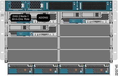
In the one-armed mode of operation clients send application requests through the multilayer switch feature card (MSFC), which routes them to a virtual IP address (VIP) within the Application Control Engine (ACE), which is configured with a single VLAN to handle client and server communication. Client requests arrive at the VIP and the ACE picks the appropriate server and then uses the destination Network Address Translation (NAT) to rewrite the destination IP to that of the rserver and rewrite the source IP with one from the nat-pool. Once the client request is fully NATed, it is sent to the server over the same VLAN which it was originally received. The server responds to the Cisco ACE based on the source IP of the request. The Cisco ACE receives the response. The ACE then changes the source IP to be the VIP and routes the traffic to the MSFC.
The MSFC then forwards the response to the client. Figure 3 displays these transactions at a high level.
Figure 3 One-Armed Mode Design Transactions
ACE Virtualization
Virtualization is a prevalent trend in the enterprise today. From virtual application containers to virtual machines, the ability to optimize the use of physical resources and provide logical isolation is gaining momentum. The advancement of virtualization technologies includes the enterprise network and the intelligent services it offers.
The Cisco ACE supports device partitioning where a single physical device may provide multiple logical devices. This virtualization functionality allows system administrators to assign a single virtual ACE device to a business unit or application to achieve application performance goals or service level agreements (SLAs). The flexibility of virtualization allows the system administrator to deploy network-based services according to the individual business requirements of the customer and technical requirements of the application. Service isolation is achieved without purchasing another dedicated appliance that consumes more space and power in the data center.
SSL Offload
The Cisco ACE is capable of providing secure transport services to applications residing in the data center. The Cisco ACE implements its own SSL stack and does not rely on any version of OpenSSL. The Cisco ACE supports TLS 1.0, SSLv3, and SSLv2/3 hybrid protocols. There are three SSL relevant deployment models available to each ACE virtual context:
•
•
•
SSL URL Rewrite Offload
Because the server is unaware of the encrypted traffic flowing between the client and the ACE, the server may return to the client a URL in the Location header of HTTP redirect responses (301: Moved Permanently or 302: Found) in the form http://www.cisco.com instead of https://www.cisco.com. In this case, the client makes a request to the unencrypted insecure URL, even though the original request was for a secure URL. Because the client connection changes to HTTP, the requested data may not be available from the server using a clear text connection.
To solve this problem, the ACE provides SSL URL rewrite, which changes the redirect URL from http:// to https:// in the Location response header from the server before sending the response to the client. By using URL rewrite, you can avoid insecure HTTP redirects. All client connections to the Web server will be SSL, ensuring the secure delivery of HTTPS content back to the client. The ACE uses regular expression matching to determine whether the URL needs rewriting. If a Location response header matches the specified regular expression, the ACE rewrites the URL. In addition, the ACE provides commands to add or change the SSL and the clear port numbers.
Session Persistence
Session persistence is the ability to forward client requests to the same server for the duration of a session. Microsoft supports session persistence for their Microsoft Exchange environment via the following methods:
•
•
The Cisco ACE supports each of these methods, but given the presence of proxy services in the enterprise, Cisco recommends using the cookie sticky method to guarantee load distribution across the server farm wherever possible as session-based cookies present unique values to use for load balancing.
In addition, the Cisco ACE supports the replication of sticky information between devices and their respective virtual contexts. This provides a highly available solution that maintains the integrity of each client's session.
Health Monitoring
The Cisco ACE device is capable of tracking the state of a server and determining its eligibility for processing connections in the server farm. The Cisco ACE uses a simple pass/fail verdict, but has many recovery and failures configurations, including probe intervals, timeouts, and expected results. Each of these features contributes to an intelligent load-balancing decision by the ACE context.
The predefined probe types currently available on the ACE module are:
•
•
•
•
•
•
•
•
•
•
•
•
•
•
•
Note that the potential probe possibilities available via scripting make the Cisco ACE an even more flexible and powerful application-aware device. In terms of scalability, the Cisco ACE module can support 1000 open probe sockets simultaneously.
Cisco Unified Computing System Hardware
The UCS components included in this solution:
•
•
I/O Adapters
The blade server has various Converged Network Adapters (CNA) options. The following CNA option was used in this Cisco Validated Design:
•
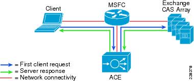
The UCS M81KR VIC allows multiple complete I/O configurations to be provisioned in virtualized or non-virtualized environments using just-in-time provisioning, providing tremendous system flexibility and allowing consolidation of multiple physical adapters. It delivers uncompromising virtualization support, including hardware-based implementation of Cisco VN-Link technology and pass-through switching. System security and manageability is improved by providing visibility and portability of network polices and security all the way to the virtual machine. Figure 4 shows the types of interfaces supported on the M81KR VIC.
Figure 4 FC and Ethernet Interfaces Supported on the M81KR VIC
The virtual interface card makes Cisco VN-Link connections to the parent fabric interconnects, which allows virtual links to connect virtual NICs in virtual machines to virtual interfaces in the interconnect. Virtual links then can be managed, network profiles applied, and interfaces dynamically reprovisioned as virtual machines move between servers in the system.
Cisco UCS 2100 Series Fabric Extenders
The Cisco UCS 2104XP Fabric Extender brings the I/O fabric into the blade server chassis and supports up to four 10-Gbps connections between blade servers and the parent fabric interconnect, simplifying diagnostics, cabling, and management. The fabric extender multiplexes and forwards all traffic using a cut-through architecture over one to four 10-Gbps unified fabric connections. All traffic is passed to the parent fabric interconnect, where network profiles are managed efficiently and effectively by the fabric interconnects. Each of up to two fabric extenders per blade server chassis has eight 10GBASE-KR connections to the blade chassis midplane, with one connection to each fabric extender from each of the chassis' eight half slots. This configuration gives each half-width blade server access to each of two 10-Gbps unified fabric connections for high throughput and redundancy.
The benefits of the fabric extender design include:
•
•
•
•
•
•
•
UCS 6100 XP Series Fabric Interconnect
The UCS 6100 XP fabric interconnect is based on the Nexus 5000 product line. However, unlike the Nexus 5000 products, it provides additional functionality of managing the UCS chassis with the embedded UCS manager. A single 6140 XP switch can support multiple UCS chassis with either half-slot or full-width blades.
Some of the salient features provided by the switch are:
•
•
•
•
•
•
In this solution, two UCS 6120 Fabric Interconnects were configured in a cluster pair for redundancy and were configured in End Host Mode. Because the Nexus 1000V switch is used in this solution, fabric failover in the Service Profiles of EXS hosts did not have to be enabled. This is because in a configuration where there is a bridge (Nexus 1000V or VMware VSwitch) downstream from the UCS 6120 fabric interconnects, the MAC address learning on the switches will take care of failover without the fabric failover feature.
UCS Service Profiles
Programmatically Deploying Server Resources
Cisco UCS Manager provides centralized management capabilities, creates a unified management domain, and serves as the central nervous system of the Cisco UCS. Cisco UCS Manager is embedded device management software that manages the system from end-to-end as a single logical entity through an intuitive GUI, CLI, or XML API. Cisco UCS Manager implements role- and policy-based management using service profiles and templates. This construct improves IT productivity and business agility. Now infrastructure can be provisioned in minutes instead of days, shifting IT's focus from maintenance to strategic initiatives.
Dynamic Provisioning with Service Profiles
Cisco UCS resources are abstract in the sense that their identity, I/O configuration, MAC addresses and WWNs, firmware versions, BIOS boot order, and network attributes (including QoS settings, ACLs, pin groups, and threshold policies) all are programmable using a just-in-time deployment model. The manager stores this identity, connectivity, and configuration information in service profiles that reside on the Cisco UCS 6100 Series Fabric Interconnect. A service profile can be applied to any blade server to provision it with the characteristics required to support a specific software stack. A service profile allows server and network definitions to move within the management domain, enabling flexibility in the use of system resources. Service profile templates allow different classes of resources to be defined and applied to a number of resources, each with its own unique identities assigned from predetermined pools.
VMware VSphere 4.0
In 2009, VMware introduced its next-generation virtualization solution, VMware Vsphere 4, which builds upon ESX 3.5 and provides greater levels of scalability, security, and availability to virtualized environments. In addition to improvements in performance and utilization of CPU, memory, and I/O, VSphere 4 also offers users the option to assign up to eight virtual CPU to a virtual machine—giving system administrators more flexibility in their virtual server farms as processor-intensive workloads continue to increase.
VSphere 4 also provides the VMware VCenter Server that allows system administrators to manage their ESX hosts and virtual machines on a centralized management platform. With the Cisco Nexus 1000V Distributed Virtual Switch integrated into the VCenter Server, deploying and administering virtual machines is similar to deploying and administering physical servers. Network administrators can continue to own the responsibility for configuring and monitoring network resources for virtualized servers as they did with physical servers. System administrator can continue to "plug-in" their virtual machines into network ports that have Layer 2 configurations, port access and security policies, monitoring features, etc., that have been pre-defined by their network administrators, in the same way they would plug in their physical servers to a previously-configured access switch. In this virtualized environment, the system administrator has the added benefit of the network port configuration/policies moving with the virtual machine if it is ever migrated to different server hardware.
Nexus 1000V Virtual Switch
Operating inside the VMware ESX hypervisor, the Cisco Nexus 1000V distributed switch supports Cisco VN-Link server virtualization technology that allows virtual machines to be connected upstream through definitions of policies. These security and network policies follow the virtual machine when it is moved through VMotion onto different ESX hosts.
Since the Nexus 1000V runs on NXOS, network administrators can configure this virtual switch with the command line interface they are already familiar with and pre-define the network policies and connectivity options to match the configuration and policies in the upstream access switches. Server administrators can then later assign these network policies to their new virtual machines using the VCenter Server GUI, making it so much easier and faster to deploy new servers as they do not have to wait for the network configuration to be put in place by the network administrators in order to bring their servers online. This also has significant positive impact for customers who regularly use the DRS functionality found in vSphere to balance Guest load on ESX Hosts. The Network Profile can now follow the guest as it is moved by vMotion between hosts. Table 5 points out how operationally the Nexus 1000V saves time for server administrators deploying virtual machines and allows network administrators to continue doing what they are used to with the tools with which they are already familiar.
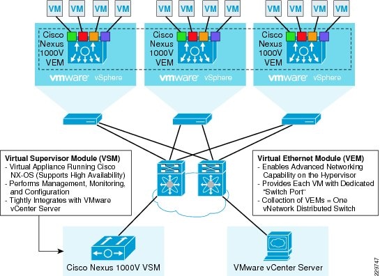
To better understand how the Nexus 1000V works, it is important to understand the software components of the Nexus 1000V—the Virtual Supervisor Module (VSM) and the Virtual Ethernet Module (VEM). It is also important to understand how the physical interfaces on a physical server map to virtual switches and virtual network interface cards (vNICs). The physical NICs on an ESX host are used as uplinks to the physical network infrastructure, e.g., the upstream access switch. Virtual network interfaces are the network interfaces on the virtual machines—whatever guest operating system is installed on the virtual machine will see these vNICs as physical NICs—so that the guest operating system can use standard network interface drivers (e.g., Intel ProSet). The Nexus 1000V, or the virtual switch, connects the virtual network interfaces to the physical NICs. Because the Nexus 1000V is a virtual distributed switch, it provides virtual switching across a cluster of ESX hosts and through the installation of a VEM on ESX. The VSM is a virtual machine running NX-OS that is created upon the installation of the Nexus 1000V; it is the control plane of the virtual distributed switch.
Each time an ESX host is installed, it is also configured with a VEM that is a virtual line card providing the virtual network interfaces to the hosted VMs as well as the system interfaces on the ESX host for host management and for communicating with the VSM. Any time configuration changes are made through VCenter to the virtual networking, the VSM pushes these changes down to the affected VEMs on their ESX hosts. Since the switching functionality resides on the VEMs themselves, the Nexus 1000V distributed switch can continue providing switching functionality even if the VSM is offline. Figure 5 illustrates how each VM is connected to the overall Nexus 1000V distributed switch through VEMs and managed by the VSM through VCenter.
Figure 5 Network Connectivity of VMs Through Nexus 1000V to Data Center LAN
NAM Appliance for Virtual Network Monitoring
With NAM 4.2, the Cisco NAM Appliances extend into the virtual networking layer, simplifying manageability of Cisco Nexus 1000V switch environments by offering visibility into the VM network, including interactions across virtual machines and virtual interfaces. The Cisco NAM devices provide combined network and application performance analytics that are essential in addressing service delivery challenges in the virtualized data center. The Cisco NAM Appliances can:
•
•
•
•
•
•
Figure 6 shows the NAM product family. The NAM 2200 appliance is used in this solution.
Figure 6 NAM Product Family
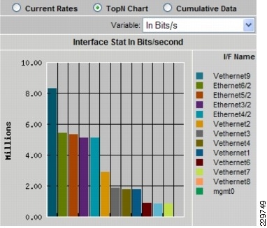
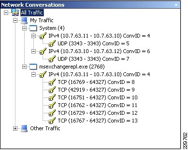
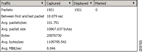
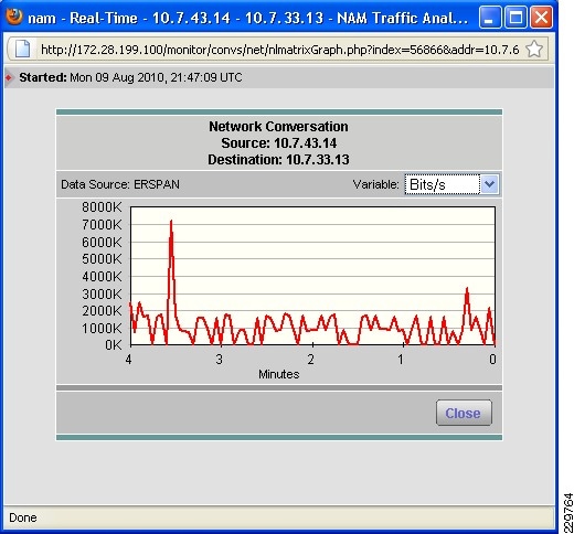
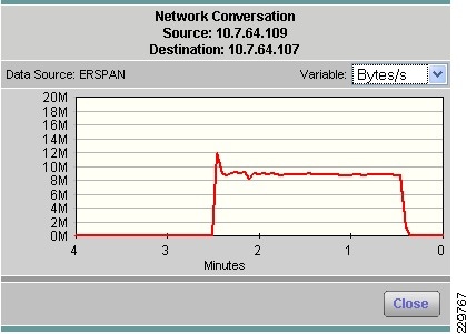
Integrated with the Cisco Network Analysis Module (NAM) appliance, ERSPAN can be configured on the Nexus 1000V to provide bandwidth statistics for each virtual machine. Reports on bandwidth utilization for various traffic types, such as Exchange user data, management, and DAG replication, can be generated to ensure that the overall network design can support the traffic levels generated by the application servers. For Exchange 2010 mailbox replication, for example, the bandwidth utilization by replication or database seeding traffic from any mailbox server configured in a DAG can be reported through the NAM appliance. Traffic generated by the VMotion of the Hub Transport/CAS or AD/DNS VMs can be monitored and reported real-time or historically.
Figure 7 Single-Screen View of Traffic Utilization from Both Physical and Virtual Interfaces
NetApp Storage Technologies and Benefits
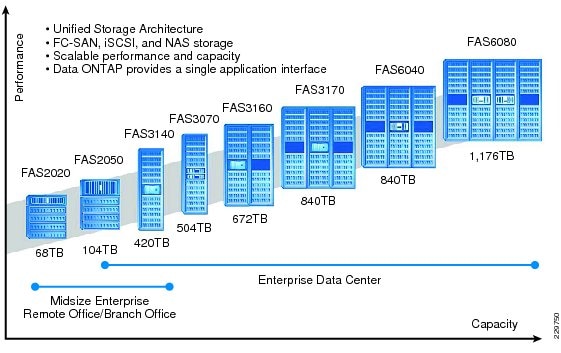
NetApp solutions begin with Data ONTAP® 7G, the fundamental software platform that runs on all NetApp storage systems. Data ONTAP 7G is a highly optimized, scalable operating system that supports mixed NAS and SAN environments and a range of protocols, including Fibre Channel, iSCSI, FCoE, NFS, and CIFS. It also includes a patented file system and storage virtualization capabilities. Leveraging the Data ONTAP 7G platform, the NetApp Unified Storage Architecture offers the flexibility to manage, support, and scale to business environments by using a single set of knowledge and tools. From the remote office to the data center, our customers collect, distribute, and manage data from all locations and applications at the same time. This allows the investment to scale by standardizing processes, cutting management time, and increasing availability. Figure 8 shows the different NetApp Unified Storage Architecture platforms.
Figure 8 NetApp Unified Storage Architecture Platforms
The NetApp storage hardware platform used in this solution is the FAS3170. The FAS3100 series is an ideal platform for primary and secondary storage for a Microsoft Exchange deployment. An array of NetApp tools and enhancements are available to augment the storage platform. These tools assist in deployment, backup, recovery, replication, management, and data protection. This solution makes use of a subset of these tools and enhancements.
RAID-DP
RAID-DP® (http://www.netapp.com/us/products/platform-os/raid-dp.html) is NetApp's implementation of double-parity RAID 6, which is an extension of NetApp's original Data ONTAP WAFL® RAID 4 design. Unlike other RAID technologies, RAID-DP provides the ability to achieve a higher level of data protection without any performance effect while consuming a minimal amount of storage.
SATA
The performance acceleration provided by WAFL (http://blogs.netapp.com/extensible_netapp/2008/10/what-is-wafl-pa.html) and the double-disk protection provided by RAID-DP make economical and large-capacity SATA drives practical for production application use. In addition, to negate the read latencies associated with large drives, SATA drives can be used with NetApp Flash Cache (http://www.netapp.com/us/products/storage-systems/flash-cache/flash-cache.html), which significantly increases performance with large working set sizes. SATA drives are more susceptible to unrecoverable BIT errors and operational failures. Without high-performance double-disk RAID protection such as RAID-DP, large SATA disk drives are more prone to failure, especially during their long RAID reconstruction time for a single drive failure. Table 6 compares RAID types and the probability of data loss in a five-year period.
For additional information about Flash Cache and Exchange Server 2010, see Using Flash Cache for Exchange 2010 (http://www.netapp.com/us/library/technical-reports/tr-3867.html).
For additional information on Exchange Server and RAID-DP, see http://media.netapp.com/documents/tr-3574.pdf.
Thin Provisioning and FlexVol
Thin provisioning is a function of NetApp FlexVol®, which allows storage to be provisioned just like traditional storage. However, it is not consumed until the data is written (just-in-time storage). Use NetApp ApplianceWatch (http://blogs.netapp.com/storage_nuts_n_bolts/2010/06/netapp-appliancewatch-for-microsofts-scom-and-scvmmhyper-v.html) in Microsoft's SCOM to monitor thin provisioned LUNs, increasing disk efficiency. Microsoft recommends a 20% growth factor above the database size and a 20% free disk space in the database LUN which on disk is over 45% free disk space.
Deduplication
NetApp deduplication technology leverages NetApp WAFL block sharing to perform protocol-agnostic data-in-place deduplication as a property of the storage itself. With legacy versions of Exchange Server most customers saw 1-5% deduplication rates, while with Exchange Server 2010 customers are seeing 10-35% deduplication rates. In a virtualized environment, it is not uncommon to see 90% deduplication rates on the application and operating system data.
Snapshot
NetApp Snapshot™ technology provides zero-cost, near-instantaneous backup, point-in-time copies of the volume or LUN by preserving Data ONTAP WAFL consistency points (CPs). Creating Snapshot copies incurs minimal performance effect because data is never moved, as it is with other copy-out technologies. The cost for Snapshot copies is at the rate of block-level changes, not 100% for each backup as it is with mirror copies. Using Snapshot can result in savings in storage cost for backup and restore purposes and opens up a number of efficient data management possibilities. SnapManager for Microsoft Exchange is tightly coupled with Microsoft Exchange Server and integrates directly with the Microsoft Volume Shadow Copy Service (VSS). This allows consistent backups and also provides a fully supported solution from both NetApp and Microsoft.
Backup and Recovery
NetApp SnapManager for Microsoft Exchange decreases the time required to complete both backup and recovery operations for Microsoft Exchange Server. The SnapManager for Exchange software and the FAS3170 storage array allow the IT department to perform near-instantaneous backups and rapid restores. SnapManager for Microsoft Exchange is tightly coupled with Microsoft Exchange Server 2010 and integrates directly with the Microsoft Volume Shadow Copy Service (VSS). This allows consistent backups and also provides a fully-supported solution from both NetApp and Microsoft. SnapManager for Exchange provides the flexibility to schedule and automate the Exchange backup verification, with additional built-in capabilities for nondisruptive and concurrent verifications. Database verification is not a requirement when in a DAG configuration.
SnapManager for Exchange can be configured to initiate a copy backup (Snapshot copy) of another database with a retention policy of one Snapshot copy. This enables the administrator to perform a nearly instant reseed should one be required. SnapManager for Microsoft Exchange allows quick and easy restoration of Exchange data to any server, including both point-in-time and roll-forward restoration options. This helps to speed disaster recovery and facilitates testing of the Snapshot restore procedure before actual need arises. NetApp Single Mailbox Recovery software delivers the ability to restore an individual mailbox or an individual e-mail message quickly and easily. It also enables the rapid recovery of Exchange data at any level of granularity-storage group, database, folder, single mailbox, or single message, and restores folders, messages, attachments, calendar notes, contacts, and tasks from any recent Snapshot copy. Single Mailbox Recovery can directly read the contents of SnapManager Snapshot copies without the assistance of Exchange Server and rapidly search archived Snapshot copies for deleted messages that are no longer in the current mailbox. Using the Advanced Find feature, it is possible to search across all mailboxes in an archive EDB file by keyword or other criteria and quickly find the desired item. For additional best practices on SnapManager for Exchange, see SnapManager 6.0 for Microsoft Exchange Best Practices Guide (http://www.netapp.com/us/library/technical-reports/tr-3845.html).
NetApp Strategy for Storage Efficiency
As seen in the previous section on technologies for storage efficiency, NetApp's strategy for storage efficiency is based on the built-in foundation of storage virtualization and unified storage provided by its core Data ONTAP operating system and the WAFL file system. Unlike its competitors' technologies, NetApp's technologies surrounding its FAS and V-Series product line have storage efficiency built into their core. Customers who already have other vendors' storage systems and disk shelves can still leverage all the storage saving features that come with the NetApp FAS system simply by using the NetApp V-Series product line. This is again in alignment with NetApp's philosophy of storage efficiency because customers can continue to use their existing third-party storage infrastructure and disk shelves, yet save more by leveraging NetApp's storage-efficient technologies.
NetApp Storage Provisioning
SnapDrive® for Windows®—Provisions storage resources and is the storage provider performing VSS backup.
Data ONTAP Powershell Toolkit—This toolkit is a collection of PowerShell cmdlets for facilitating integration of Data ONTAP into Windows environment and management tools by providing easy-to-use cmdlets for low-level Data ONTAP APIs.
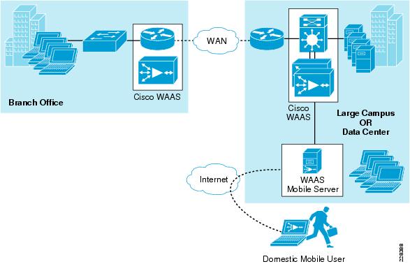
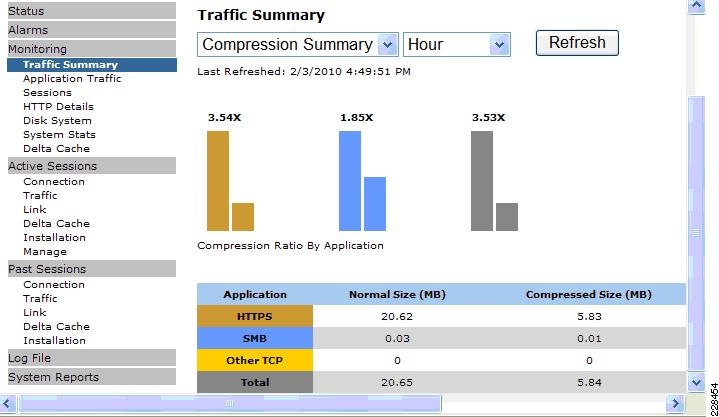
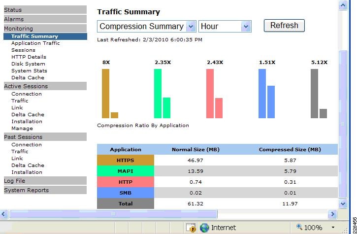
Cisco Wide Area Application Services for Branch Users
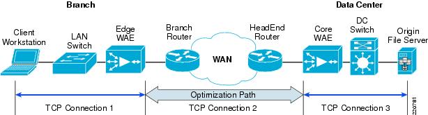
To provide optimization and acceleration services between the branch and data center, a Cisco WAAS appliance was deployed at the data center WAN aggregation tier in a one-armed deployment and a WAAS network module was deployed in the Integrated Services Router at the branch edge.
To appreciate how the Cisco Wide Area Application Services (Cisco WAAS) provides WAN optimization and application acceleration benefits to the enterprise, consider the basic types of centralized application messages that are transmitted between remote branches. For simplicity, two basic types are identified:
•
•
The Cisco WAAS uses the technologies described in the following sections to enable optimized Exchange Outlook communication between the branch office outlook clients and Exchange servers in the data center by providing TFO optimization, LZ compression, DRE caching, MAPI acceleration, and SSL acceleration.
Advanced Compression Using DRE and LZ Compression
Data Redundancy Elimination (DRE) is an advanced form of network compression that allows the Cisco WAAS to maintain an application-independent history of previously-seen data from TCP byte streams. Lempel-Ziv (LZ) compression uses a standard compression algorithm for lossless storage. The combination of using DRE and LZ reduces the number of redundant packets that traverse the WAN, thereby conserving WAN bandwidth, improving application transaction performance, and significantly reducing the time for repeated bulk transfers of the same application.
TCP Flow Optimization
The Cisco WAAS TCP Flow Optimization (TFO) uses a robust TCP proxy to safely optimize TCP at the Cisco WAE device by applying TCP-compliant optimizations to shield the clients and servers from poor TCP behavior due to WAN conditions. The Cisco WAAS TFO improves throughput and reliability for clients and servers in WAN environments through increases in the TCP window sizing and scaling enhancements—as well as through the implementation of congestion management and recovery techniques—to ensure that the maximum throughput is restored in the event of packet loss. By default, Cisco WAAS provides only TFO for RDP. If RDP compression and encryption are disabled, then full optimization (TFO+ DRE/LZ) can be enabled for RDP flows.
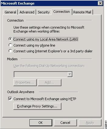
Messaging Application Programming Interface (MAPI) Protocol Acceleration
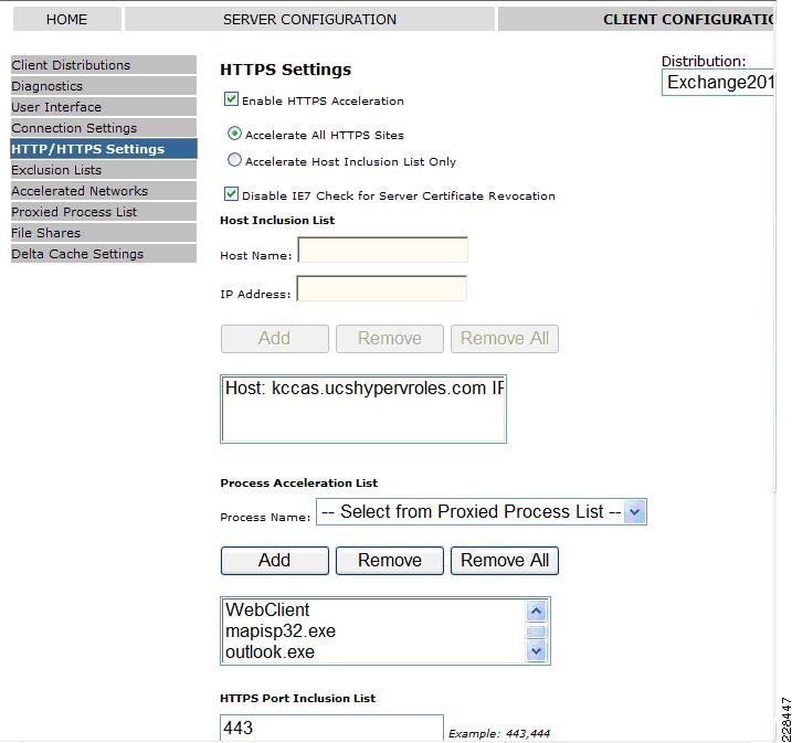
The MAPI application accelerator accelerates Microsoft Outlook Exchange 2010 traffic that uses the Messaging Application Programming Interface (MAPI) protocol. Microsoft Outlook 2010 clients are supported. Clients can be configured with Outlook in cached or non-cached mode; both modes are accelerated. Secure connections that use message authentication (signing) or encryption or Outlook Anywhere connections (MAPI over HTTP/HTTPS) are not accelerated by the MAPI application accelerator. To allow internal Outlook users to benefit from application acceleration of their Exchange traffic, these users can leverage the Outlook Anywhere option to run MAPI over HTTPS, in which case SSL acceleration of their E-mail traffic can be leveraged.
Secure Socket Layer (SSL) Protocol Acceleration
Cisco WAAS provides the widest set of customer use cases for deploying WAN optimization into SSL-secured environments. For example, many industries and organizations use Web proxy servers to front-end their key business process applications in the data center and encrypt with SSL from the proxy server to remote users in branch sites. Cisco WAAS provides optimized performance for delivering these applications, while preserving the SSL encryption end-to-end-something competitive products' SSL implementations do not support. To maximize application traffic security, WAAS devices provide additional encryption for data stored at rest and can be deployed in an end-to-end SSL-optimized architecture with Cisco ACE application switches for SSL offload.
Cisco WAAS provides SSL optimization capabilities that integrate fully with existing data center key management and trust models and can be used by both WAN optimization and application acceleration components. Private keys and certificates are stored in a secure vault on the Cisco WAAS Central Manager. The private keys and certificates are distributed in a secure manner to the Cisco WAAS devices in the data center and stored in a secure vault, maintaining the trust boundaries of server private keys. SSL optimization through Cisco WAAS is fully transparent to end users and servers and requires no changes to the network environment.
Among the several cryptographic protocols used for encryption, SSL/TLS is one of the most important. SSL/TLS-secured applications represent a growing percentage of traffic traversing WAN links today. Encrypted secure traffic represents a large and growing class of WAN data. Standard data redundancy elimination (DRE) techniques cannot optimize this WAN data because the encryption process generates an ever-changing stream of data, making even redundant data inherently non-reducible and eliminating the possibility of removing duplicate byte patterns. Without specific SSL optimization, Cisco WAAS can still provide general optimization for such encrypted traffic with transport flow optimization (TFO). Applying TFO to the encrypted secure data can be helpful in many situations in which the network has a high bandwidth delay product (BDP)1 and is unable to fill the pipe.
Termination of the SSL session and decryption of the traffic is required to apply specific SSL optimizations such as Cisco WAAS DRE and Lempel-Ziv (LZ) compression techniques to the data. Minimally, SSL optimization requires the capability to:
•
•
•
•
The capability to terminate SSL sessions and apply WAN optimizations to encrypted data requires access to the server private keys. Further, the clear-text data received as a result of decryption must be stored on the disk for future reference to gain the full benefits of DRE. These requirements pose serious security challenges in an environment in which data security is paramount. Security by itself is the most important and sensitive aspect of any WAN optimization solution that offers SSL acceleration.
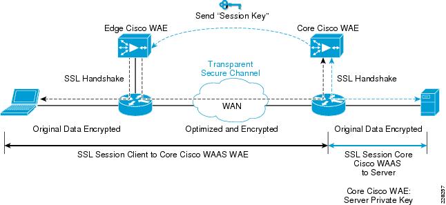
Figure 9 SSL Protocol Acceleration
During initial client SSL handshake, the core Cisco WAE in the data center participates in the conversation.
The connection between the Cisco WAEs is established securely using the Cisco WAE device certificates and the Cisco WAEs cross-authenticate each other:
•
•
•
•
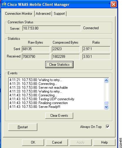
Cisco WAAS Mobile
In addition to Cisco WAAS for branch optimization, Cisco offers Cisco WAAS Mobile for telecommuters, mobile users, and small branch and home office users who access corporate networks and need accelerated application performance. Cisco WAAS Mobile client is purpose-built for Microsoft Windows PCs and laptops. To provide WAAS Mobile services to remote users, a Windows 2008 WAAS server was deployed as a virtual machine on the UCS to support user connections into the data center Exchange server farm.
Advanced Data Transfer Compression
Cisco WAAS Mobile maintains a persistent and bi-directional history of data on both the mobile PC and the Cisco WAAS Mobile server. This history can be used in current and future transfers, across different VPN sessions, or after a reboot, to minimize bandwidth consumption and to improve performance. In addition, instead of using a single algorithm for all file types, Cisco WAAS Mobile uses a file-format specific compression to provide higher-density compression than generic compression for Microsoft Word, Excel, and PowerPoint files, Adobe Shockwave Flash (SWF) files, ZIP files, and JPEG, GIF, and PNG files.
Application-Specific Acceleration
Cisco WAAS Mobile reduces application-specific latency for a broad range of applications, including Microsoft Outlook Messaging Application Programming Interface (MAPI), Windows file servers, or network-attached storage using CIFS, HTTP, HTTPS, and other TCP-based applications, such as RDP.
Transport Optimization
Cisco WAAS Mobile extends Cisco WAAS technologies to handle the timing variations found in packet switched wireless networks, the significant bandwidth latency problems of broadband satellite links, and noisy Wi-Fi and digital subscriber line (DSL) connections. The result is significantly higher link resiliency.
Solution Design and Deployment
Exchange 2010 Design Considerations
Microsoft best practices are followed for the different Exchange server roles for the servers that are deployed virtually on Vsphere as well as for the servers installed natively on the UCS blade servers. To summarize, these are the requirements being satisfied in this solution validation that are relevant to processor and memory allocation.
Large Data Center Scenario
•
•
•
Small Data Center Scenario
•
•
Processor Cores—Factors to Consider
There are several factors to consider when determining how many processor cores are needed by your mailbox server, regardless of whether the server is physical or virtualized.
•
A mailbox server in a DAG needs additional CPU cycles to support the services for cluster monitoring and database replication. Calculating processor requirements for mailboxes in a DAG is complex. For further details and more examples of calculating processor capacity for your DAG mailbox servers, refer to Microsoft documentation at: http://technet.microsoft.com/en-us/library/ee712771.aspx and the Microsoft Exchange 2010 Excel calculator available at http://msexchangeteam.com/archive/2009/11/09/453117.aspx.
•
Depending on whether the mailbox server is standalone or part of a DAG, the Microsoft Exchange calculator assumes that peak CPU % should not exceed certain values.
–
If the mailbox server is not hosting any other Exchange roles, then the number of cores to assign the mailbox server role should be sufficient so the peak CPU utilization by the mailbox services is no more than 70%. If multiple roles are installed on the server, then there should be enough processor cores assigned so that peak CPU utilization by mailbox services should not exceed 35%.
–
If the mailbox server is in a DAG, then there should be enough processor cores assigned so that peak CPU utilization by mailbox services after a single or double-node failure is no more than 80%. If the server also hosts other Exchange roles, then there should be enough processor cores so that CPU utilization for the mailbox services should be under 40%.
•
The megacycles available for a given processor must be determined so it can be used as an input to calculate how many processors are required on each mailbox server. This applies to both the manual calculation as well as the calculation through the Microsoft Exchange 2010 Excel calculator. The Microsoft Exchange 2010 calculator baseline of 3300 megacycles/core was determined by performance testing with 3.33 MHz Intel X5470 8-core processors. In order to determine the corresponding megacycles/core for a different processor, the SPECint2006 and SPECfp2006 baseline values available at http://www.spec.org/cgi-bin/osgresults?conf=rint2006 and http://www.spec.org/cgi-bin/osgresults?conf=rfp2006 can be used.
The following are the available megacycles with hyperthreading disabled estimated by Cisco for each of the processor models used in this solution.
–
–
•
Determining how many processors are required on a given server to support a given number of mailboxes involves using the Microsoft Exchange 2010 calculator to figure out how many megacycles are required to support a targeted failure scenario. The targeted failure scenario for each primary data center in this solution is the situation in which a given mailbox server is hosting the maximum number of active mailboxes after a server or site failover.
Then there are factors to consider if the mailbox servers will be virtualized.
•
Previously in ESX 3.5, the maximum number of virtual CPUs that could be assigned to a given virtual machine was four. In VSphere 4, the limit has been raised to eight.
•
Hypervisors add processing overhead, which varies depending on the hypervisor platform. Microsoft recommends that 10% CPU virtualization overhead be accommodated when figuring out how many processors to assign to a virtualized Exchange server. A VMware Capacity Planner assessment can provide the VSphere virtualization overhead for a given Exchange 2010 environment. It is important to test out the Exchange workload with tools like LoadGen to verify if the optimal number of virtual CPUs has been assigned. That is the approach taken in this solution.
Microsoft Exchange 2010 Calculator
Given the Exchange scenario in this solution, the appropriate input values are fed into the Excel calculator. This section explains what input parameters were used for the Small DC scenario and the Large DC scenario.
Small DC Scenario Calculations
1.
2.
3.
Primary Datacenter Mailbox Servers
4
4300
Secondary Datacenter Mailbox Servers
4
4300
4.
5.
6.
Large DC Calculations
1.
2.
3.
Primary Datacenter Mailbox Servers
8
4600
Secondary Datacenter Mailbox Servers
8
4600
4.
5.
However, use of LoadGen for Exchange 2010 in the validation of this solution made it necessary for us to assign the 1G and 512MB mailboxes differently to each database. For this solution validation, each database contained only one mailbox size, so that 1G mailboxes were separated from the 512MB mailboxes. In addition, this solution followed the Microsoft recommendation of keeping databases sizes under 2TB; as a result, each mailbox server in the Large DC ended up with the following:
•
•
•
Similarly, the third mailbox server in the DR DC has two databases, each with 1100 1G mailboxes, and two databases, each with 900 512MB mailboxes, although all 8000 mailboxes are passive until a site failover occurs.
6.
To summarize the results of the calculations provided by the Microsoft Exchange calculator, Table 7 and Table 8 are presented below. These tables list the number of processor cores and amount of RAM assigned to each server in the Small and Large DCs (the corresponding backup server in the DR DC also has the same configuration). Note that separate from the Excel calculator, the server core ratio and memory requirements for the AD/DNS server were followed to determine the resource allocation for that role.
Table 7 Small DC Resource Allocation
Small DC active Exchange server with HT, CAS, Mailbox roles
4
Intel Xeon E5520
32GB1
DR DC passive Exchange server with HT, CAS, Mailbox roles
4
Intel Xeon E5520
32GB1
Small DC active AD/DNS
1
Intel Xeon E5520
4GB
DR DC passive AD/DNS
1
Intel Xeon E5520
4GB
1 Note that 32GB of RAM was assigned since the hosting UCS blade/ESX host had plenty of spare memory. There were 48GB total RAM and only 4GB was needed for the AD/DNS VM on that ESX host, leaving 32GB+ available to the MBX+HT+CAS VM.
Configuring CPU and Memory on Exchange VMs
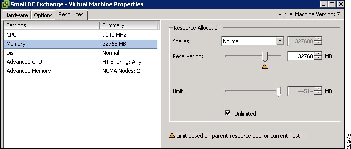
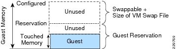
Using VCenter client for configuration, the four vCPUs and 32 GB memory resources are assigned to the VM for the Small Data Center that hosts all three Exchange roles. Since Exchange is memory-intensive and mission-critical, it is wise to minimize ESX host-level swapping and ensure that this VM will always get its memory allocation if more VMs are added to the ESX host in the future. Therefore, a memory reservation of 32GB is also configured as shown in Figure 10.
Figure 10 Memory Reservation Setting
Since the Small DC Exchange server resides on the same ESX host as the Small DC AD/DNS VM in this solution and there are no other VMs on that ESX host, the Small DC Exchange server can benefit from the memory ballooning mechanism available in VSphere. If the AD/DNS VM performance testing reveals that it does not require the full 4GB of RAM, then by leaving the AD/DNS VM configured without a memory reservation allows the Small DC Exchange server to be configured with up to 40GB of RAM as more users are added to the Small DC environment. For more details on memory ballooning and memory management in Vsphere, see ESX Memory Management Concepts.
This solution follows VSphere best practices of avoiding over committing CPU resources on an ESX host; therefore, the total number of vCPUs assigned to both the Exchange server VM and the AD/DNS VM does not exceed the eight total processor cores available on the UCS blade. Without CPU overcommittment, it is not necessary to set a CPU reservation for either VM. Because of this, if additional VMs are added to this ESX host, Vsphere will have flexibility in balancing workloads across the CPU for optimal utilization of available cores. However, it may make sense to configure a CPU Reservation at that time on the Exchange VM to deliver on SLAs. For more information on this topic, see CPU Configuration Guidelines for VSphere.
The same configuration method and best practices were followed when assigning CPU and memory resources to the CAS/HT and AD/DNS VMs in the Large DC and the backup VMs in the DR DC.
Server Networking
The following sections describes the networking configuration and deployment details for the physical Exchange servers and the Exchange VMs. The topics addressed are:
•
•
•
Traffic Isolation
Based on VMware and Microsoft recommendations, separate networks are dedicated to VMotion, host management, Exchange data, and Exchange DAG traffic. Table 9 shows whether the different physical servers and virtual machines in this solution are placed in each of the five VLANs.
M81KR (Palo) Network Interface
The M81KR network interface on a Mailbox server in the Large DC, LargeMbox2, is a Palo VIC. Each of these virtual interfaces defined on this VIC provides a 10GE uplink to the UCS fabric interconnects and can leverage the native fabric failover provided in UCS End Host Mode.
UCS Network Configuration
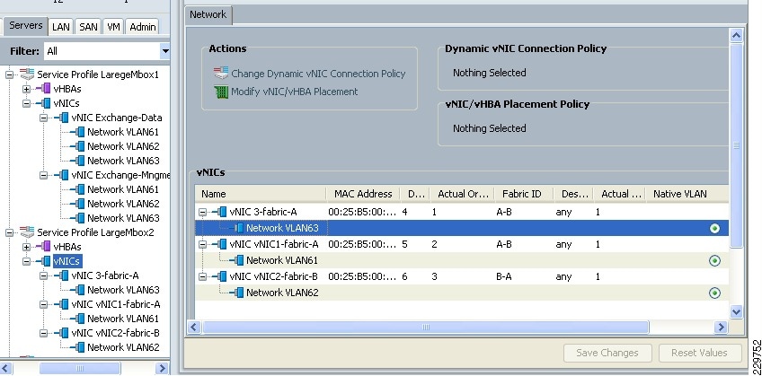
The UCS Service Profile for LargeMbox2 consists of three vNICs, each defined as a trunk and specifying its VLAN as native, as shown in Figure 11. This configuration is treated by the Fabric Interconnects as a VLAN access port configuration.
Figure 11 UCS Service Profile for Mailbox Server with Palo NICs
The NX-OS CLI configuration on the Fabric Interconnects corresponding to vNICs in the Service Profile is:
interface vethernet1094switchport trunk native vlan 61switchport trunk allowed vlan 61bind interface Ethernet1/1/5untagged cos 0no pinning server stickypinning server pinning-failure link-downno cdp enableinterface vethernet1097switchport trunk native vlan 62switchport trunk allowed vlan 62bind interface Ethernet1/1/5untagged cos 0no pinning server stickypinning server pinning-failure link-downno cdp enableinterface vethernet1098switchport trunk native vlan 63switchport trunk allowed vlan 63bind interface Ethernet1/1/5untagged cos 0no pinning server stickypinning server pinning-failure link-downno cdp enableWindows Networking
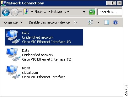
The three Palo-based vNICs in the UCS Service Profile for LargeMbox2 are presented in Windows as three separate physical adapters.
Figure 12 Palo vNICs Presented in Windows
Each of the vNICs were shown as a "Cisco VIC Ethernet Interface #.." once the Windows 2008 x64 drivers were downloaded and installed from the Cisco site for UCS driver downloads (under Unified Computing System Adapters in the main menu: http://www.cisco.com/cisco/web/download/index.html).
As with other physical adapters, these VIC Ethernet interfaces can be monitored from within the OS with packet sniffers like Microsoft Network Monitor or Wireshark.
Since native fabric failover for each vNIC in the UCS Service Profile is enabled, failover from Fabric Interconnect A to Fabric Interconnect B should happen automatically without further configuration required in Windows. This was tested by simulating 4000 users sending 150 msgs/day with LoadGen targeting this Mailbox server while disabling the Server Ports on Fabric Interconnect A. LoadGen traffic continued without disruption while the failover to Fabric B occurred.
The version of Windows drivers for the Palo VIC used in this solution is as shown in Figure 13.
Figure 13 Palo VIC Windows Driver
Nexus 1000V and Virtual Machine Networking
The M81KR network interfaces were used on the UCS blades installed with ESX hosts.
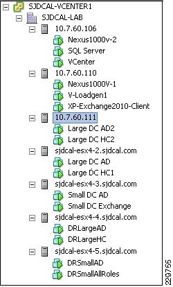
Figure 14 shows the inventory of hosts in the SJDCAL cluster in the Large DC as shown in VCenter.
Figure 14 VCenter Display of ESX Host Inventory
Nexus 1000V Uplinks
The ESX host "sjdcal-esx4-2.sjdcal.com" is a UCS blade server installed with the M81KR (Palo) adapter. With regard to networking, its UCS Service Profile must contain the following specifications:
•
•
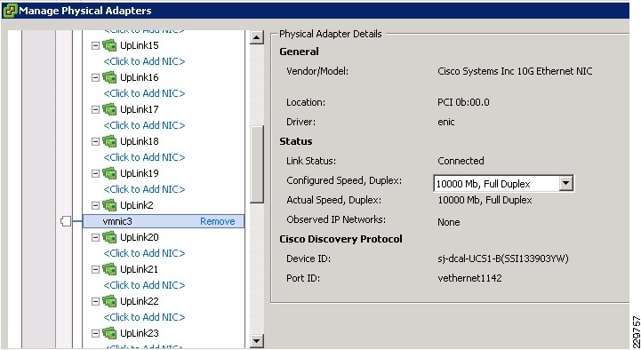
VCenter shows that the four vNICs have been assigned as uplinks on the Nexus 1000V switch (or VEM) on this blade as shown in Figure 15. Vmnic3 is one of the vNICs pinned to Fabric Interconnect B as shown in Figure 16, while other Vmnics are pinned to Fabric Interconnect A.
Figure 15 M81KR 10GE vNICs as Nexus 1000V Uplinks
Figure 16 Vmnic3 Pinned to Fabric Interconnect UCS1-B
Nexus 1000V Port Groups and VM network interfaces
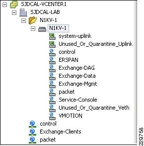
Since each ESX host is installed with a VEM for that Nexus 1000V, any of the configured port groups on that Nexus 1000V can be assigned as a network interface to a VM on any of the ESX hosts. Figure 17 shows the different port groups configured, which included not only the VLANs mentioned earlier for the different traffic types, but also includes the mandatory control, packet, and Service-Console port groups, a VMotion port group, and a port group for encapsulated remote SPAN traffic (ERSPAN) that will allow traffic involving the VMs to be monitored by the NAM appliance.
Figure 17 Port Groups on Nexus 1000V
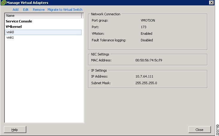
Both the ERSPAN and the VMotion port groups are defined as VMkernel port groups, as shown in Figure 18 and Figure 19, since they are access ports for the ESX hypervisors.
Figure 18 VMotion VMKernel Port Group
Figure 19 ERSPAN VMkernel Port Group
UCS Fabric Failover
To validate that Exchange sessions can continue when a fabric failover occurs, testing was done in the Large DC. The testing involved disabling the server ports on Fabric Interconnect A that served as uplinks for the UCS blade server hosting a native mailbox server and the UCS blade server with ESX hosting Exchange VMs. Three different traffic types were being generated when the uplinks were disabled:
•
•
•
Table 10 shows that network connectivity was maintained through the fabric failover.
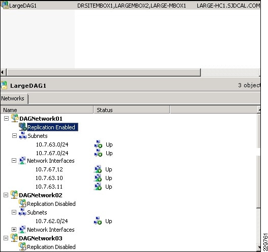
DAG Network
The two physical mailbox servers in the Large data center are clustered together with the backup mailbox server in the DR data center, in DAG LargeDAG1. Exchange automatically detects potential DAG networks and lists them in Exchange Management Console. If there are multiple interfaces on the mailbox server, as in this solution, then all of the multiple detected subnets and network interfaces for the local and remote mailbox servers that are participating in this DAG are shown. Some of these subnets are intended to carry MAPI or Exchange data traffic only, while some of these subnets are intended for VM Management traffic. Therefore, it is important to designate which DAG network should be the network used for DAG cluster/replication traffic so that the particular network is always used unless it is unavailable. As shown in Figure 20, replication is enabled on the DAGNetwork01 which consists of the interfaces on the three mailbox servers (DRSiteMbox1, LargeMBOX2, and LARGE-MBOX1) that are dedicated to cluster-interconnect, log shipping, and seeding traffic generated within the DAG. Should DAGNetwork01 become unavailable because the server uplink or data path goes down, then DAGNetwork02, which carries MAPI traffic, will be used even though the replication setting for this network is set to disabled. While Microsoft supports a configuration in which the DAG traffic and MAPI traffic are carried over the same network, as in the case where the mailbox server does not have enough network interfaces, it is recommended that the two traffic types are separated on dedicated networks.
Figure 20 DAG Replication Network
Monitoring DAG Traffic
The DAG network carries traffic for database seeding, log shipping, and cluster status communication. Table 11 shows the UDP or TCP ports used by these traffic types.
Table 11 UDP and TCP Ports Used by Traffic Types
Cluster and Cluster Link Health Status
UDP
3343
Log Shipping
TCP
64327
Database Seeding
TCP
64327
Microsoft Network Monitor running on one of the physical mailbox servers in the Large DC confirms the different traffic types occurring on the local 10.7.63.X DAG subnet. Figure 21 shows the TCP and UDP flows for log shipping and cluster status communication typically occurring on the DAG network to synchronize the database copies on both mailbox servers. Some packet sniffers, like Wireshark shown in Figure 22, can also summarize the amount of bandwidth consumed on the DAG network for database replication. Note that the Microsoft Excel calculator should be used to estimate initially whether the DAG network has enough capacity to support the log shipping, database seeding, and cluster communication for the expected user workload. For this solution, 10GE on the DC LAN as well as for the links between the DC sites were calculated to be sufficient in the Excel calculator and verified to be sufficient through monitoring the links during LoadGen tests.
Figure 21 Packet Sniffer Listing of DAG Network Traffic
Figure 22 Bandwidth Consumption on DAG Network
The NAM appliance can be used to monitor DAG traffic utilization involving the virtualized mailbox servers in the Small DC and the DR DC. During a test run with LoadGen simulating activity from 4000 Outlook_150 users, a browser to the NAM appliance, as shown in Figure 23, was used to report real-time the bandwidth utilization on the DAG network for the active Small DC mailbox server. The NAM appliance provides the option of monitoring such traffic real-time or with historical reports. The next section gives the details on how the NAM appliance was configured with the Nexus 1000V to provide these statistics.
Figure 23 NAM Real-Time Statistics for DAG Network Traffic
NAM Reporting of ERSPAN from Nexus 1000V
For the Small DC Exchange server VM, the NAM appliance can be used to collect ERSPAN packets from the Nexus 1000V and report on bandwidth utilization of traffic such as log shipping traffic on the DAG network. ERSPAN can be enabled on the Nexus 1000V to forward GRE-encapsulated SPAN traffic captured on specific VLANs, Ethernet, or Vethernet interfaces to the IP address of the NAM appliance. Figure 24 illustrates the ERSPAN configuration used in this solution, with the 1GE Layer 3 port of the NAM appliance connected to a remote Layer 3 network and the ERSPAN traffic from the Nexus 1000V traversing the Layer 2 access and Layer 3 core of the Data Center to get to the NAM appliance.
Figure 24 ERSPAN Configuration
Encapsulated remote (ER) SPAN monitors traffic in multiple network devices across an IP network and sends that traffic in an encapsulated envelope to destination analyzers. In contrast, Local SPAN cannot forward traffic through the IP network. ERSPAN can be used to monitor traffic remotely. ERSPAN sources can be ports or VLANs.
In Figure 24, the ingress and egress traffic for Host A, or the Small DC VM, are monitored using ERSPAN configured on the Nexus 1000V. Additional VMs as represented by Host B can be added to the ERSPAN configuration and separate monitoring sessions could be configured on the Nexus 1000V for each host so that the monitoring and reporting to the NAM could be enabled or disabled independently for each host depending on the situation being tested. This minimizes the amount of unnecessary ERSPAN traffic generated across the network. Encapsulated ERSPAN packets are routed from Host A through the routed network to the destination device or the Layer 2 switch on the management network where the NAM appliance resides. The ERSPAN packets are then de-capsulated and processed by the attached network analyzer.
Similarly, the Nexus 1000V can be configured to send ERSPAN packets to the NAM to report on VMotion traffic since the VMotion VMkernel interfaces used by the ESX hosts are configured on the Nexus 1000V. Figure 25 and Figure 26 demonstrate how the NAM appliance is useful in gaining visibility into bandwidth utilization of bursty traffic like VMotion traffic. In Figure 25 and Figure 26, we can see that the amount of traffic generated by VMotion varies, depending on the particular memory footprint being copied across the link to the second ESX host. The bandwidth utilization in two separate instances were captured and reported real-time by the NAM appliance for the VMotion of one of the HT/CAS VMs from one ESX host to another in the Large DC. Depending on the amount of traffic that needs to be monitored and your particular network infrastructure, there is also the option to use the 10GE data ports instead of the 1GE port on the NAM appliance to monitor and collect traffic. The NAM appliance in that case would be connected directly to a SPAN-capable 10GE switch in the DC aggregation or core tier. The Nexus 1000V would then be configured to ERSPAN DAG or VMotion traffic to that 10GE switch and local SPAN would forward that traffic of interest to the directly-attached NAM appliance.
Figure 25 First Burst of VMotion Traffic Generated by Migration of HT/CAS VM
Figure 26 Second Burst of VMotion Traffic Generated by Second Migration of HT/CAS VM
Nexus 1000V Configuration for ERSPAN
The Nexus 1000V in this solution is configured to ERSPAN DAG and VMotion traffic to the management port on the NAM appliance. Separate ERSPAN monitoring sessions have been configured on the Nexus 1000V to allow administrators to enable and disable monitoring of VMotion and DAG traffic separately, so that the amount of packets that are duplicated across the network in the ERSPAN are minimized to what is absolutely necessary for reporting or troubleshooting. Additional monitoring sessions can be created for Exchange data traffic and other traffic types using the similar set of commands shown below.
In Nexus 1000V and Virtual Machine Networking, we already saw that the ERSPAN port group, or port profile, was created and displayed through VSphere VCenter. The command-line output from the SSH session with the Nexus 1000V shows that the ERSPAN port profile is defined to be on the ESX host management VLAN 60, the native VLAN on the UCS. This access VLAN must also be designated as a system VLAN in this port profile.
port-profile type vethernet ERSPANcapability l3controlvmware port-groupswitchport mode accessswitchport access vlan 60no shutdownsystem vlan 60state enabledAfter the interfaces on the Nexus 1000V that are used to carry VMotion traffic are identified, we can proceed to configure the ERSPAN monitor sessions. The following are the Vethernet interfaces on the three ESX hosts in the Large DC that have been configured to participate in VMotion:
interface Vethernet2inherit port-profile VMOTIONdescription VMware VMkernel, vmk0vmware dvport 171interface Vethernet3inherit port-profile VMOTIONdescription VMware VMkernel, vmk0vmware dvport 172interface Vethernet4inherit port-profile VMOTIONdescription VMware VMkernel, vmk0vmware dvport 173A separate monitoring session is configured to ERSPAN VMotion packets to the NAM appliance, designating the above three Vethernet interfaces as interface sources of those packets. In this configuration, packets inbound to each interface will be ERSPANed. The destination IP is the IP address of the 1GE management port of the NAM appliance.
monitor session 3 type erspan-sourcedescription ERSPAN to NAM- VMotionsource interface Vethernet3 rxsource interface Vethernet4 rxsource interface Vethernet2 rxdestination ip 172.28.199.100erspan-id 51ip ttl 64ip prec 0ip dscp 0mtu 1500Figure 27 UCS in the DR DC
As Figure 27 depicts, the UCS in the DR DC has two ESX hosts to support:
•
•
Therefore, the Nexus 1000V in the DR DC is configured to ERSPAN both VMotion as well as DAG traffic. As can be seen below, a separate additional monitoring session is configured on the Nexus 1000V for ERSPAN of DAG traffic to the NAM appliance. In this case, however, the source of the packets of interest is the entire DAG VLAN, or VLAN 63. The rx direction of the packets is chosen since every interface that is part of VLAN 63 will be monitored.
monitor session 4 type erspan-sourcedescription ERSPAN to NAM- DAGsource vlan 63 rxdestination ip 172.28.199.100erspan-id 52ip ttl 64ip prec 0ip dscp 0mtu 1500Storage Configuration for Exchange 2010
NetApp RAID-DP Storage Calculator for Exchange 2010
The storage sizing was modified from what a customer would actually deploy so that two different user mailbox sizes could be utilized with the Microsoft LoadGen 2010 tool. VMware vSphere has a LUN size constraint of 2TB and customers that need to exceed that size must connect directly to the storage from the virtual machine using iSCSI. The storage was provisioned with enough capacity to keep one week of snapshots. The FAS3170 controller is sized to handle the DR site Exchange Server workload, as well as the servers themselves in a boot from SAN configuration. The Large and Small sites have headroom for other workloads. If the Exchange workload is isolated at these sites the controller can be downsized into a 3160 and 3140 respectively. The NetApp sizer assumes every user's mailbox will be at the maximum quota. Many customers choose to size their environment at the average mailbox size plus 20%. The caveat to thin provisioning is that the LUN capacity provisioned in a volume is greater than the volume size. This requires monitoring with tools such as Microsoft's System Center Operations Manager (http://www.netapp.com/us/products/management-software/appliancewatch.html), NetApp Appliance Watch, and the NetApp Data Ontap Powershell Toolkit (http://communities.netapp.com/community/interfaces_and_tools/data_ontap_powershell_toolkit). Enabling deduplication would further reduce the storage by approximately 30%, however it was not enabled in the testing. Microsoft LoadGen 2010 has a small message mix and enabling deduplication in such an environment would show abnormally high deduplication rates. Sizing for deduplication must occur during rollout. Deduplication rates are variable depending on the customer workload and the space for the original data must exist before you can run deduplication.
Small Site
FAS3170—16 1TB physical disks in a single aggregate
Thin Provisioning Disabled—21 1TB physical disks
Large Site
FAS3170—53 1TB physical disks in 4 aggregates
Thin Provisioning Disabled—70 1TB physical disks
DR Site
FAS3170—44 1TB physical disks in 3 aggregates
Thin Provisioning Disabled—58 1TB physical disks
Aggregate, Volume, and LUN Sizing
The aggregate contains all of the physical disks for a workload and for Exchange this has traditionally been split into two aggregates, database and transaction log. Microsoft supports placing a database and its transaction log onto the same physical disk when in a DAG configuration.
The volume is generally sized at 90% the aggregate size, housing both the actual LUNs and the snapshots of those LUNs. In the case of Exchange 2010, deduplication and thin provisioning can provide a large space savings over 50% in some cases.
Exchange capacity sizing should be calculated in the Microsoft Exchange 2010 Mailbox Server Role Requirements Calculator (http://msexchangeteam.com/archive/2009/11/09/453117.aspx). This calculates the database, content index, transaction logs, a growth factor, and 20% free disk space. When using management tools to monitor volume space and growth rates, you can thin provision the LUNs so that the nearly 50% of the LUN that is empty does not take up space in the volume. Deduplication will further decrease the amount of storage consumed in the volume.
NetApp Best Practices for Exchange 2010
Storage Design and Layout
•
•
•
•
•
•
NetApp recommends separating Exchange database and transaction log files onto separate LUNs and separate volumes whenever possible. This allows greater flexibility for backup and recovery procedures as well as data protection strategies.
•
Sizing and Capacity Planning
Use the NetApp Sizing Tool for Exchange to size all Exchange Server deployments using NetApp storage. The NetApp Sizing Tool is available through NetApp technical support.
Database Maintenance
Enable online maintenance to run 24x7.
Data Protection
Use SnapManager for Exchange when deploying Exchange Server 2010 on NetApp storage. SME performs the data migration from local disks to NetApp LUNs. It also manages that data, handling all backup, restore, and verification tasks.
High Availability (Deployment)
•
•
High Availability (Storage Design)
•
•
High Availability (Volume Separation)
Place active and passive copies of the mailbox database in separate volumes.
High Availability (Backup)
Perform VSS backups on one of the passive nodes.
VSphere Virtualization Best Practices for Exchange 2010
This section discusses best practices developed by VMware for Exchange 2010 which were followed in this solution and referenced in the above sections. Note that many of these best practices are applicable to VSphere virtualization in general. For additional details on VSphere best practices and sizing guidance for Exchange 2010, consult the following VMware documents: http://www.vmware.com/solutions/business-critical-apps/exchange/resources.html.
A solidly-designed ESX host platform is crucial to the successful implementation of enterprise applications such as Exchange. Before we address best practices specific to the Exchange application, the following sections outline general best practices for designing vSphere.
CPU Configuration Guidelines
Physical and Virtual CPUs
VMware uses the terms virtual CPU (vCPU) and physical CPU to distinguish between the processors within the virtual machine and the underlying physical x86/x64-based processor cores. Virtual machines with more than one virtual CPU are also called SMP (symmetric multi-processing) virtual machines. The virtual machine monitor (VMM) is responsible for virtualizing the CPUs. When a virtual machine starts running, control transfers to the VMM, which is responsible for virtualizing guest OS instructions.
Virtual SMP
VMware Virtual Symmetric Multi-Processing (Virtual SMP) enhances virtual machine performance by enabling a single virtual machine to use multiple physical processor cores simultaneously. vSphere supports use of up to eight virtual CPUs per virtual machine. The biggest advantage of an SMP system is the ability to use multiple processors to execute multiple tasks concurrently, thereby increasing throughput (for example, the number of transactions per second). Only workloads that support parallelization (including multiple processes or multiple threads that can run in parallel) can really benefit from SMP.
The virtual processors from SMP-enabled virtual machines are co-scheduled. That is, if physical processor cores are available, the virtual processors are mapped one-to-one onto physical processors and are then run simultaneously. In other words, if one vCPU in the virtual machine is running, a second vCPU is co-scheduled so that they execute nearly synchronously. The following points should be considered when using multiple vCPUs:
•
•
In VMware ESX™ 4, the CPU scheduler has undergone several improvements to provide better performance and scalability; for details, see VMware vSphere 4: The CPU Scheduler in VMware ESX 4 (http://www.vmware.com/files/pdf/perf-vsphere-cpu_scheduler.pdf). For example, in ESX 4, the relaxed co-scheduling algorithm has been refined so that scheduling constraints due to co-scheduling requirements are further reduced. These improvements have resulted in better linear scalability and performance of Exchange workloads, while reducing inefficiencies introduced by idle vSMP virtual machines. Consequently, in vSphere, the larger 4-way and 8-way virtual machines exhibit great scalability and are a much more viable option if there is a requirement to scale up versus scale out.
Consequently, VMware recommends the following practices:
•
•
•
While larger virtual machines are possible in vSphere, VMware recommends reducing the number of virtual CPUs if monitoring of the actual workload shows that the Exchange application is not benefitting from the increased virtual CPUs. For more background, see the "ESX CPU Considerations" section in the white paper Performance Best Practices for VMware vSphere 4 (http://www.vmware.com/pdf/Perf_Best_Practices_vSphere4.0.pdf).
Setting a CPU Reservation sets a guaranteed CPU allocation for the virtual machine. This practice is generally not recommended because the reserved resources are not available to other virtual machines and flexibility is often required to manage changing workloads. However, SLAs and multi-tenancy may require a guaranteed amount of compute resource to be available. In these cases, reservations ensure these requirements are met. VMware has conducted tests on virtual CPU over-commitment with SAP and SQL, showing that the performance degradation inside the virtual machines is linearly reciprocal to the over-commitment. As the performance degradation is "graceful," any virtual CPU over-commitment can be effectively managed by using VMware DRS and VMware VMotion™ to move virtual machines to other ESX hosts to obtain more processing power.
Hyper-Threading
Hyper-threading technology (recent versions of which are called symmetric multithreading or SMT) allows a single physical processor core to behave like two logical processors, essentially allowing two independent threads to run simultaneously. Unlike having twice as many processor cores—which can roughly double performance—hyper-threading can provide anywhere from a slight to a significant increase in system performance by keeping the processor pipeline busier. For example, an ESX host system enabled for SMT on an 8-core server will see 16 threads that appear as 16 logical processors.
Memory Configuration Guidelines
This section provides guidelines for allocation of memory to Exchange virtual machines. The guidelines outlined here take into account vSphere memory overhead and the virtual machine memory settings.
ESX Memory Management Concepts
vSphere virtualizes guest physical memory by adding an extra level of address translation. Shadow page tables make it possible to provide this additional translation with little or no overhead. Managing memory in the hypervisor enables the following:
•
•
•
For more details about vSphere memory management concepts, consult the VMware vSphere Resource Management Guide (http://www.vmware.com/pdf/vsphere4/r40_u1/vsp_40_u1_resource_mgmt.pdf).
Virtual Machine Memory Concepts
Figure 28 illustrates the use of memory settings parameters in the virtual machine.
Figure 28 Virtual Machine Memory Settings
The vSphere memory settings for a virtual machine include the following parameters:
•
•
•
•
Allocating Memory to Exchange Virtual Machines
Microsoft has developed a thorough sizing methodology for Exchange server that has matured over the last couple of versions of Exchange. VMware recommends using the memory sizing guidelines set by Microsoft. Simplistically the amount of memory required for an Exchange server is driven by its role and, if it is a mailbox server, the number of mailboxes on that server. From the perspective of VMware, the architect should consider the VMM memory requirements on top of the memory requirements for the Exchange server itself.
As Exchange servers are memory intensive and performance is often a key factor (e.g., in production environments), VMware recommends the following practices:
•
–
–
•
•
•
•
Advanced Memory Management
The guidelines described above are purposely conservative to avoid kernel swapping between ESX and the guest OS—important due to the mission-critical nature of Exchange, which must often meet stringent SLAs, and the memory intensive nature of the application. This best practice can also apply to non-production systems with high performance SLAs for developers and testers who support production environments.
However, it is feasible that once the Exchange workload is known and predictable, if VMware vCenter™ reports that steady state active memory usage is below the amount of memory on the ESX host, then the reservation settings may be relaxed to the steady state active memory value. This scenario is discussed in the VMworld® 2009 presentation, TA2627—Understanding "Host" and "Guest" Memory Usage and Related Memory Management Concepts (http://www.vmworld2009.com/docs/DOC-3817; VMworld account is required for access).
Storage Virtualization
VMFS is a cluster file system that provides storage virtualization optimized for virtual machines. Each virtual machine is encapsulated in a small set of files and VMFS is the default storage system for these files on physical SCSI disks and partitions. VMware supports Fibre-Channel, iSCSI, and NAS shared-storage protocols.
It is preferable to deploy virtual machine files on shared storage to take advantage of VMware VMotion, VMware High Availability (HA), and VMware Distributed Resource Scheduler (DRS). This is considered a best practice for mission-critical Exchange deployments, which are often installed on third-party, shared-storage management solutions.
VMware storage virtualization can be categorized into three layers of storage technology, as illustrated in Figure 29. The storage array is the bottom layer, consisting of physical disks presented as logical disks (storage array volumes or LUNs) to the layer above, with the virtual environment occupied by vSphere. Storage array LUNs that are formatted as VMFS volumes in which virtual disks can be created. Virtual machines consist of virtual disks that are presented to the guest operating system as disks that can be partitioned and used in file systems.
Figure 29 VMware Storage Virtualization Stack
Storage Multipathing
VMware recommends you set up a minimum of four paths from an ESX host to a storage array, which means the host requires at least two HBA ports.
Figure 30 Storage Multipathing Requirements for vSphere
The terms used in Figure 30 are:
•
•
•
Raw Device Mapping
VMFS also supports Raw Device Mapping (RDM). RDM allows a virtual machine to directly access a volume on the physical storage subsystem and can only be used with Fibre Channel or iSCSI. RDM can be thought of as providing a symbolic link from a VMFS volume to a raw volume. The mapping makes volumes appear as files in a VMFS volume. The mapping file, not the raw volume, is referenced in the virtual machine configuration.
There are no concrete recommendations for using VMFS or RDM in Exchange deployments, although Table 12 summarizes some of the options and trade-offs. For a more complete discussion, consult the VMware SAN System Design and Deployment Guide (http://www.vmware.com/resources/guides.html).
It is also possible and even advantageous in some circumstances to mix VMFS and RDM in Exchange environments under the following conditions:
•
•
•
•
•
•
•
•
•
It is important to note that there are several different shared-storage options available to ESX (iSCSI, Fibre Channel, NAS, etc.); however, Microsoft does not currently support NFS for the Mailbox Server role (clustered or standalone). For Mailbox servers that belong to a Database Availability Group, only Fibre Channel is currently supported; iSCSI can be used for standalone mailbox servers. To see the most recent list of compatibilities, consult the latest VMware Compatibility Guides.
Number of Virtual Machines per LUN
The number of virtual machines allocated to a VMFS LUN influences the final architecture. Figure 31 illustrates the concepts and highlights the differences between a one-to-one and many-to-one virtual machine-to-LUN assignment.
Figure 31 One versus Many Virtual Machines in a LUN
Networking Configuration Guidelines
This section covers design guidelines for the virtual networking environment and provides configuration examples at the ESX host level for Exchange Server 2010 installations.
Note
Virtual Networking Concepts
The virtual networking layer consists of the virtual network devices through which virtual machines and the service console interface with the rest of the network and users. In addition, ESX hosts use the virtual networking layer to communicate with iSCSI SANs and NAS storage.
The virtual networking layer includes virtual network adapters and the virtual switches. Virtual switches are the key networking components in vSphere. They are "built to order" at run time and are implemented in much the same way as a modern Ethernet switch, supporting functions equivalent to VLANs based on the IEEE 802.1Q protocol.
Virtual Switches and Port Groups
Virtual switches work like Ethernet switches and support VLAN segmentation at the port level. VLANs in vSphere allow logical groupings of switch ports to communicate as if all ports were on the same physical LAN segment. VLANs require tagging of Ethernet frames with the 802.1Q tag (based on IEEE protocol standards), and vSphere enables port-based VLAN tagging based on the switch ports. The VMware Virtual Networking Concepts document discusses three different configuration modes to tag:
•
•
•
The most common configuration is VST mode. VST mode requires provisioning one port group on a virtual switch for each VLAN and attaching the virtual machine's virtual adapter to the port group of the virtual switch. The virtual switch port group tags all outbound frames and removes tags for all inbound frames. It also ensures that frames on one VLAN are isolated from other VLANs. VST mode requires that the physical switch provide a trunk (trunking is the technology that allows information from multiple VLANs to be carried over a single link).
Port groups in vSphere are templates for creating virtual ports with a particular set of specifications. In vSphere, there are three types of port group/virtual switch connections:
•
•
•
More than one connection type can exist on a single virtual switch or each connection type can exist on its own virtual switch.
NIC Teaming
vSphere allows a single virtual switch to be connected to multiple, physical Ethernet adapters using a feature called NIC teaming. This provides redundancy and/or aggregation. Note that in this validated design, NIC teaming is not implemented since the Nexus 1000V and M81KR network interface used provided the redundancy and aggregation.
Virtual Networking Best Practices
The standard VMware networking best practices apply to running Exchange on vSphere:
•
•
•
•
•
•
Sample Exchange Virtual Network Configuration
Figure 32 is an example of how a network layout for an Exchange production environment might look.
Figure 32 Sample Network Layout for Exchange Environment
Figure 32 illustrates how networking is handled at the ESX level. Each ESX host must have virtual switches architected to handle the type of network traffic that will be assigned to each of the different virtual machines. Figure 32 represents a sample configuration where the production resource pool is split between two physical servers (to reflect redundancy for HA considerations). From a networking perspective, make sure that production environment network traffic remains separate from VMware VMotion and Admin traffic. An effective way to handle this is by introducing VLAN technology to logically separate the traffic.
Each virtual machine acts independently and remains isolated until networking is configured. What makes the environment different than that in the physical world is that it must have an internal network configured to establish communication between virtual machines residing on the same physical ESX host. This network traffic is handled through the virtual switch.
Each physical NIC can be configured to connect directly to an assigned VLAN, but the VMware VMotion and Admin networks are not used as heavily as production networks. One practice is to team all the NICs on the ESX host, connect them to trunk ports on the switch, and use VLAN tagging to direct the traffic at the switch level. This allows for better bandwidth utilization and frees up server capacity for production traffic when the VMware VMotion and Admin VLANs are not in heavy use.
Data Center Network Architecture
Figure 33 Cisco Data Center Network Architecture
This Cisco Validated Design uses the Cisco Data Center Business Advantage Architecture as its data center design because of the strengths and features offered in that architecture. The following highlights features of the Cisco Data Center Business Advantage Architecture that were implemented in this Cisco Validated Design:
•
•
•
•
•
•
•
•
•
•
•
•
•
For further details on the Cisco Data Center Business Advantage Architecture with details on leveraging the Catalyst 6500 series as the Service Chassis at the aggregation layer, refer to the following Cisco Validated Design: http://www.cisco.com/en/US/solutions/ns340/ns414/ns742/ns743/ns994/landing_service_patterns.html.
Global Site Selector Configuration for Site Failover
Small DC
The Cisco GSS appliance is deployed at the WAN edge of each data center to provide site selection between the active data center and the DR DC based on whether the targeted Exchange Client Access server is available. If the Small DC site becomes unavailable, users should be redirected to the Exchange server in the DR DC. This section provides details on how that was configured on the GSS appliance and tested in the Small DC-DR DC environment.
The GSS appliance can be accessed for configuration and reporting through a browser interface to the management IP address. Under the "DNS Rules" tab, different parameter sets have to be configured in order to create DNS rules which are ultimately define the failover scheme. Figure 34 lists the different parameters that compose the DNS rules:
•
•
•
•
•
Figure 34 Configure DNS Rule
In order for all users of the Small DC to be re-directed to the DR DC Exchange server in the case of a site failover, the GSS is configured with the parameters shown in the following series of screenshots. (Note that the sequence of steps is the reverse of what is listed in Figure 34 since it matches the actual workflow.) There is an explanation above each figure which describes what the given configuration means.
1.
Figure 35 Configure Answers for DNS Rule
2.
Figure 36 Configure Answer Group
3.
Figure 37 Configure Domain Lists
4.
Figure 38 Configure Source Address List
5.
Figure 39 Summary of DNS Rule created for Small DC Server Failover to DR DC
Figure 40 Details of DNS Rule for Small DC Server Failover to DR DC
Note that the DNS TTL setting works by extending the time the client DNS server can cache the lookup response. The default of 20 seconds is recommended to reduce the traffic to the GSS, yet still have the client DNS server check frequently enough to provide the best answer. It also improves the chance that the client will get a better answer should the service they were using go down. A shorter TTL increases traffic to the GSS, although it does make any service transitions quicker to the client. For Exchange, using the default setting is sufficient.
6.
Figure 41 GSS Directs User to Small DC Exchange Server
7.
As shown in Figure 42, the Monitoring pane on the GSS appliance shows that the Exchange server in the Small DC is indeed unreachable and the other Exchange server should be used.
Figure 42 GSS Monitoring Reports Small DC Exchanger Server Offline
8.
Figure 43 GSS Redirection of User to Exchange Server in DR DC
Large DC
For the Large DC, there are redundant CAS server on the combined HT/CAS VMs. This means that under normal operations, Large DC user workloads are load balanced between the two CAS servers using a hardware load balancer like the Cisco ACE. This section does not go into the details of the Cisco ACE configuration for load balancing Exchange 2010, since it was covered in Load Balancing for an Exchange 2010 Environment.
With ACE load balancing client connections to the Large DC CAS servers, the GSS appliance would be configured to use the KAL-AP interface with the ACE device to monitor the status and health of the CAS servers. As long as the ACE reports that any of its CAS servers are online and available, the GSS can continue to direct Large DC users to the Large DC servers. However, once the ACE reports that none of the CAS servers are online, the GSS will re-direct Large DC users to the CAS server in the DR DC. The details below show how the GSS and ACE were configured for this purpose.
Since the Large DC GSS appliance will be polling the ACE device for the status of the CAS servers, the ACE context for the Exchange load balancing must have a command inserted to allow KAL-AP packets to be received by the ACE.
1.
class-map type management match-any GSS2 match protocol kalap-udp source-address 10.7.53.90 255.255.255.2552.
policy-map type management first-match GSS-accessclass GSSpermit3.
interface vlan 53description to server-side vlanip address 10.7.53.8 255.255.255.0alias 10.7.53.7 255.255.255.0peer ip address 10.7.53.9 255.255.255.0access-group input allnat-pool 1 10.7.53.200 10.7.53.200 netmask 255.255.255.0 patservice-policy input ForExchangeservice-policy input GSS-accessno shutdown4.
kalap udpip address 10.7.53.90 encryption md5 myhashsecretFigure 44 and Figure 45 show the GSS configuration for setting the CAPP hash secret for the KAL-AP keepalives.
Figure 44 Setting Hash Secret for KAL-AP on GSS
Figure 45 Configuring Shared KAL-AP KeepAlive
5.
Figure 46 Answer for Large DC has ACE VIP Address
Figure 47 DNS Rule for Large DC Users
Setting up NetApp Storage
Each DC site has a pair of FAS 3170 storage arrays equipped with disk shelves of 14 1TB 7200RPM SATA drives. Storage provisioning for this solution followed some of the NetApp best practices for Exchange 2010 and VMware best practices for Exchange virtualization. It addition, it took advantage of the storage flexibility available in Exchange 2010.
VMFS Datastore for VMotion
For each data center, a shared VMFS datastore for storing the VM images is required to support VMware VMotion of a non-mailbox server virtual machine in this solution. The ESX hosts that are participating in VMotion are given access to this shared datastore on the NetApp array by including them in the Initiator Group for that LUN. As you can see in Figure 48, the ESX servers in the Large DC are mapped to the /vol/VM/VM LUN (VMFS datastore) in the LUN Initiator Group ESXServers. The mapping involves specifying the WWPNs of the vHBAs defined in the UCS Service Profile for each ESX server in the Initiator Group "ESXServers".
Figure 48 VMFS Datastore LUN for VMotion in Large DC
Note that there is a second LUN /vol/VMFS/VMFSdatastore that is in the root aggregate that was originally used as the VMFS datastore, since the root aggregate had enough unused space and there was a shortage of disks. However, once enough additional SATA disks were brought online, the VMFS datastore was moved to the new aggregate to optimize performance and avoid the possibility of contention for disk I/O between the storage controllers and the VM operating systems. Once the new LUN was created with a few easy steps in the OnTAP FilerView UI, the location of the VM images were changed through a storage migration executed in VCenter, as shown in Figure 49.
Figure 49 Move VM Images to New VMFS Datastore Through VSphere Storage Migration
Mailbox Database and Log LUNs
Exchange 2010 now gives administrators the option to place the mailbox database files and transaction log files on the same LUNs, which may be preferable to reduce the number of LUNs tht must be managed. If flexibility in backup and recovery procedures and improved data protection is a higher priority, it is preferable that the database and log files reside on separate LUNs and volumes. Since this solution was not implemented in a production environment, the option to co-locate the database and transaction log files on the same volume was chosen given limited storage. Figure 50 lists the LUNs used in the Large DC; it shows that the database and log files were kept on separate LUNs.
Figure 50 Database and Log File Storage
Note that in addition to the db and log LUNs, there are also smaller LUNs (shown as /vol/vollargeexchange1/mp2 and /vol/vollargeexchange4/mp1 in Figure 51) created to be the mount points for the db and the log LUNs in Windows. This allows the passive copies of a database and its corresponding log files to have the same directory path as the active copies, which is a requirement in the DAG configuration.
Figure 51 shows the database and log file paths as shown in the Exchange Management console on one of the physical mailbox servers in the Large DC DAG.
Figure 51 Database and Log File Paths in Large DC DAG
Based on the NetApp storage configuration described in detail in Storage Configuration for Exchange 2010, the following volumes and aggregates shown in the screenshots below were created to support four active and four passive databases on each mailbox server in the Large DC.
Figure 52 Four Aggregates with 53 Disks Total
Figure 53 Four Volumes Sized at 90% of Aggregates for Large DC Mailboxes
The Small DC supports 1350 active users with storage provisioned to allow for the addition of a third database to allow the user base to expand up to 3000 users. There is only one aggregate of 16 disks and one volume sized at 90% of the aggregate size. The volume is shown in Figure 54.
Figure 54 Small DC Aggregate and Volume
The 1.7TB LUN and one of the 1.4TB LUNs contain the two databases for the existing 1350 users while the third 1.4TB LUN can be brought online on the Small Exchange VM once the user base grows.
Figure 55 Database LUNs for Small DC
There is a remaining LUN to hold the transaction log files and one to serve as the mount point.
Figure 56 Log and Mount Point LUNs for Small DC
In the DR DC, two aggregates, each with 14 disks, are used to store the eight passive backup databases/log files for the Large DC. One aggregate with 16 disks is used to store the same for the Small DC.
Figure 57 DR DC Aggregates for Passive Mailboxes
Fibre-Channel Storage Area Network
UCS Service Profile
For high availability, our ESX hosts need dual fibre-channel connections to our FC SAN. VSphere 4 provides native MPIO which is leveraged in this solution to provide that redundancy. Initially, the UCS Service Profile for each ESX host is configured to have one vHBA going through Fabric Interconnect A and the other going through Fabric Interconnect B. Since we have a single VSAN in this solution, both are configured on the same VSAN 200.
Figure 58 vHBA Configuration of ESX Host in UCS Service Profile
Soft Zoning and VSAN
Before proceeding to the ESX configuration on VCenter, we first make sure the soft zoning and VSAN configuration on our SAN fabric switches permit our UCS blades access to our storage array. This means that the WWPNs of the NetApp FAS 3170 controllers and the WWPNs of the vHBAs on the UCS blades must all be in VSAN 200 and part of the same zone and zoneset. On each of the FC switches in the Large DC, the VSAN and soft zoning configuration can be shown with a "show zoneset active" at the command line:
zoneset name DCAL vsan 200zone name sjdcal vsan 200* fcid 0x9e0000 [pwwn 50:0a:09:83:87:49:34:c6] <--------------WWPN of FAS 3170 controller 1* fcid 0x9e0002 [pwwn 20:00:00:00:00:01:1b:0f] [dcal-ucs-svr1-4]* fcid 0x9e0010 [pwwn 20:00:00:00:00:01:1b:af] [dcal-ucs-svr1-1]* fcid 0x9e000d [pwwn 20:00:00:00:00:01:1a:fa] [dcal-ucs-svr2-1]* fcid 0x9e0006 [pwwn 20:00:00:00:00:01:1a:9f] [dcal-ucs-svr2-2]* fcid 0x9e0005 [pwwn 20:00:00:00:00:01:1b:8e] [dcal-ucs-svr2-3]* fcid 0x9e0008 [pwwn 20:00:00:00:00:01:1a:0f] [dcal-ucs-svr2-4] <==========WWPN of UCS blade 2/4 with ESX4-4 UCS Service Profile shown in Figure 58.ESX Native MPIO
Each ESX host minimally needs FC connectivity to the VMFS datastore containing the VM images of the virtualized Exchange servers. In addition, the Small DC Exchange VM includes the mailbox server role, as does its backup Exchange VM in the DR DC. Therefore, each of these VMs is attached to RDM (Raw-Device Mapped) LUNs on the SAN for storing the mailbox database and transaction log files. Through VCenter, we can see the list of LUNs accessible by each ESX host as well as the dual paths available through the SAN fabric. Per VMWare ESX best practices for storage multipathing, an additional pair of FC paths can be added to each ESX host through secondary links between each FC switch and each controller on the FAS 3170.
Figure 59 Dual FC Paths to VMFS Datastore and RDM LUNs
ESX native MPIO allows us to specify the preferred FC path to each LUN. This can be done by selecting "Edit Settings" for the VM and selecting "Manage Paths" for the LUN in question. The pop-up window, as shown in Figure 60, allows the administrator to select the path selection method based on whether a round-robin scheme or a single path is desired. For this solution, the path selection was set to "Fixed(VMware)" and a Preferred path (marked as "Active(I/O)") is constantly used as long as it is available. Should it become unavailable, the secondary path will become the new fixed path.
Figure 60 ESX Native MPIO Path Selection
Validating Exchange Server Performance
After CPU, memory, and storage were allocated to the Exchange servers per the design considerations discussed earlier, LoadGen 2010 (v14.01.0139.000) was used to generate the 150 msg/day usage profile for the 8000 mailbox users in the large data center and the 1350 mailbox users in the small data center. Note that the 150 msg/day profile translates to 181 tasks/day for each user, since each user executes tasks such as browsing the calendar in addition to sending and receiving E-mail messages. Each test run was configured to simulate a four-hour user day to generate peak periods of traffic when measuring server performance and memory utilization. Windows Performance Monitoring was run on each server role to monitor the performance counters recommended by Microsoft for monitoring Exchange performance. When Windows Performance counters are used to monitor server performance in a VSphere VM, it is safe to assume that the results obtained are no more than 10% in error if CPU utilization stays below 80%. This is based on VMware guidance around performance testing Exchange 2010 available in their best practices documents (http://www.vmware.com/solutions/business-critical-apps/exchange/resources.html). While Windows PerfMon graphs were captured in this solution for both physical and virtualized Exchange servers, it was verified that the VCenter performance graphs for VM CPU and memory utilization reported numbers similar to the PerfMon numbers.
The details of how to use Windows 2008 Performance Monitoring can be found at http://technet.microsoft.com/en-us/library/cc770309(WS.10).aspx. Microsoft provides a list of the common and Exchange role-specific performance counters along with their acceptable thresholds: http://technet.microsoft.com/en-us/library/dd335215.aspx.
Note
Small DC
The backup Exchange VM for the Small DC that is located in the DR DC is assigned the same resources and is hosted on the same UCS blade hardware as the active Exchange VM in the Small DC. Therefore, after a site failover from the Small DC to the DR DC, it would demonstrate similar performance as that for the Small DC Exchange VM under normal operations.
The 1350 users of the Small DC are separated into two databases, so the LoadGen results at the end of a 10 hour test run, configured for a four-hour user day, show that each database of users got about a little more than 305,400 tasks. That is the expected number of tasks since there are 2.5 users days in a 10 hour period and, with each user configured for 181 tasks/user day, the expected total number of tasks is 2.5*181*675(users in each database) = 305,437.
Figure 61 LoadGen Report on 1350 Users for Small DC
The Exchange VM in the Small DC, which is configured with 32GB of RAM and 4 vCPU, hosts the 1350 active mailboxes and also hosts all three Exchange roles of Hub Transport, CAS, and Mailbox server. Windows performance monitoring on this VM, as shown in Figure 62, confirms that 32GB is more than sufficient memory, since 2-3GB are available for use while the above-configured test is running. Average CPU utilization stays between 40-60%. Note that the CPU utilization on the AD/DNS stayed under 10% with memory usage at around 1GB.
Figure 62 CPU and Memory Utilization on Small DC Exchange VM
The backup Exchange VM in the DR DC, shown as DRSmallAllRoles in the performance graph of Figure 63, has sufficient resources to support the log shipping and cluster communication with the Exchange VM in the Small DC. Average CPU utilization stays below 15% with occasional peaks under 40%. There are 2-3GB of memory available throughout the four-hour user day test.
Figure 63 CPU and Memory Utilization on DR DC Backup Exchange Server for Small DC
In addition to Windows Performance Monitoring, VCenter performance monitoring can be used to monitor CPU and memory utilization for a given VM. In the test with the Small DC 1350 active users, the VCenter performance chart for read latency on a RDM LUN containing a 675-user database can be monitored to ensure it stays below the Microsoft-recommended 50ms.
Figure 64 Disk Read Latency Reported by VCenter Performance Chart
Large DC
Under normal operations, the two physical mailbox servers in the Large DC each hosts 4000 active mailboxes and 4000 passive mailboxes. The physical mailbox server in the DR DC has a passive copy of all 8000 mailboxes. In Figure 65, the LoadGen test report shows that the expected number of user tasks were completed successfully. With 181 tasks generated for each user, 4000 users, and 2.5 user days (four-hour user day and 10 hours test duration), the total number of tasks configured and completed are 181*4000*2.5 = 1,810,000.
Figure 65 LoadGen Test Result for Large DC Normal Operations
With the above workload, CPU utilization as shown in Figure 66 stays around 32.7% on average. During the test, memory usage was monitored and it was found that about 9GB were left available, as shown in Figure 67. Both Hub Transport/CAS combined role VMs have enough CPU and memory to support 8000 mailbox users between them, as shown in Figure 66. Since CPU utilization spikes at the beginning of the LoadGen test on each HT/CAS VM, it is advisable to allocate two-four additional vCPUs to the remaining VM to handle all 8000 users if the other VM becomes unavailable.
Two AD/DNS VMs are sufficient to support the 8000 user workload. With each AD/DNS VM supporting a 4000 user population, it was observed that CPU utilization remained below 20% and about 2GB of RAM was left available after the 600MB NTDS.dit file, or the entire AD database, was cached in memory. There is plenty of headroom in the case where one AD/DNS VM fails and the other needs to take on all 8000 users.
Figure 66 CPU Utilization on Physical Mailbox Server for 4000 Large DC Users
Figure 67 Memory Available on Physical Mailbox Server for 4000 Large DC Users
Figure 68 CPU and Memory Utilization on a HT/CAS VM in Large DC for 4000 Active Users
Figure 69 CPU and Memory Utilization on AD/DNS in Large DC for 4000 Users
After a site failover from the Large DC to the DR DC, all 8000 users of the Large DC can be supported by the CPU and memory resources on the physical mailbox server in the DR DC. As the LoadGen test report in Figure 70 shows, the expected number of tasks have been executed over the 2.5 four-hour user days over a 10 hour test duration. Each user day involves 181 tasks executed, and given 8000 users, the total number of tasks is 2.5*181*8000 or 3,620,000.
Figure 70 LoadGen Test Results for Large DC Site Failover to DR DC
The performance graph in Figure 71 shows that CPU utilization on this DR mailbox server with the above workload averages around 60%. Over the course of this 10 hour test, there was at least 5GB of memory left available.
Figure 71 Performance of Physical Mailbox Server in DR DC After Site Failover
NetApp FAS 3170 Controllers
For each of the LoadGen test runs, the CPU utilization of the FAS 3170 controllers were monitored using the command "sys stat -f 1", which captures CPU utilization every second. Larger sampling intervals can be used. In the Large DC LoadGen test with 8000 active users going through a single controller for storage array access, average controller CPU utilization was 44%, with a peak of 93% which occurred infrequently and a minimum of 15%. The following is a short sample of the "systat -f 1" output that was analyzed.
CPU NFS CIFS FCP Net kB/s Disk kB/s FCP kB/s Cachein out read write in out age39% 0 0 3083 0 0 101612 78684 54781 93984 0s55% 0 0 2886 0 0 111508 38573 55052 101266 0s50% 0 0 1670 0 0 73676 101980 41521 63211 0s45% 0 0 2511 0 0 85852 68884 49342 90036 0s28% 0 0 1640 0 0 78492 110576 34002 75769 0s40% 0 0 2623 0 0 92592 82592 44216 94772 0s45% 0 0 3902 0 0 98408 1000 66698 105733 0s60% 0 0 2961 0 0 92488 44659 49306 91433 0s57% 0 0 2029 0 0 57081 127346 39214 60217 0s41% 0 0 2510 0 0 84004 60000 46276 84388 0s45% 0 0 2872 0 0 86136 50368 51917 88087 0s38% 0 0 2938 0 0 103272 71284 53206 99511 0s42% 0 0 2678 0 0 111400 34300 51225 98957 1949% 0 0 2692 0 0 88292 10708 45056 82850 1978% 0 0 2206 0 0 68267 120275 53391 59637 1941% 0 0 2356 0 0 77399 95037 40517 77346 1943% 0 0 2633 0 0 92360 47516 45783 93443 0s37% 0 0 2769 0 0 77004 97440 42237 82421 0s33% 0 0 2097 0 0 48304 56860 29441 46314 1s32% 0 0 3439 0 0 78478 12032 46886 81681 1sValidating With VMotion
To determine the effect of VMotion in this solution, the LoadGen test to simulate normal operations in the Large DC was repeated. In this test, 4000 active mailbox users are hosted on each of the two physical mailbox servers in the Large DC, with the load being balanced between the two Hub Transport/CAS VMs in that DC. A Vmotion of the first HT/CAS VM was executed and repeated several times. During the repeated VM migrations, LoadGen continued to completion without logging exceptions.
Validating WAAS Performance
WAAS Setup Between Branch and Data Center
Figure 72 WAAS Appliances and WAAS Mobile in Test Topology
Two scenarios were tested in the lab to demonstrate Cisco WAAS performance improvements, one for users at the branch office and one for remote/mobile users, as shown in Figure 72. Two Exchange client types were used in testing WAAS performance between a branch office and the data center—Outlook Anywhere and Outlook 2010 RPC/MAPI client. Exchange online mode was chosen for the Outlook clients to minimize background traffic so that it would be possible to focus the performance measurement on the E-mail attachment download. Exchange client types were used to test WAAS performance for a remote/mobile user: Outlook Anywhere and Outlook Web Access. Given the flexibility and security of Outlook Anywhere for client connectivity into the data center from either a branch office or a remote location, many enterprises may choose to deploy this client configuration at their branches to support the mobile and work-at-home lifestyles of their employees.
The scenario for branch office users consists of the following workflow:
1.
2.
3.
4.
5.
6.
This simulates a very typical scenario in any enterprise environment, for example, a manager at the corporate office sends out a Word document for review by several employees at a branch office. The caching, LZ compression, SSL acceleration, and MAPI acceleration capabilities of the WAAS devices at the data center and the branch work to minimize the amount of redundant data traversing the WAN. This is especially important for branch offices since their WAN link sizes are typically limited to 3Mbps or smaller. For these scenarios, several link sizes ranging from 768Kbps to 3Mbps were tested. Latency and packet loss numbers were chosen to represent different geographical distances between branch office and data center.
The scenario for the remote/mobile user consists of the following workflow:
1.
2.
3.
4.
Setting Up the Outlook Anywhere Server and Client
The following configurations need to be performed on the Exchange Client Access server:
1.
[PS] C:\Windows\system32>Set-RpcClientAccess -Server KCCAS -EncryptionRequired $false[PS] C:\Windows\system32>Set-RpcClientAccess -Server KCMAILBOX-2 -EncryptionRequired $false[PS] C:\Windows\system32>Set-RpcClientAccess -Server KCMAILBOX-3 -EncryptionRequired $false[PS] C:\Windows\system32>Get-RpcClientAccessServer Responsibility MaximumCo Encryption BlockedClientVersionsnnections Required------ -------------- --------- --------- ---------------------KCCAS Mailboxes 65536 FalseKCMAILBOX-2 PublicFolders 65536 FalseKCMAILBOX-3 PublicFolders 65536 False2.
Figure 73 Enabling Outlook Anywhere in Exchange Management Console
The following configuration was done on each of the Outlook 2010 clients at the branch office:
1.
2.
Figure 74 Disabling MAPI Encryption and NTLM Authentication Setting
Figure 75 NTLM Authentication for Outlook Anywhere on Server
3.
–
–
–
–
Figure 76 Enabling Outlook Anywhere on Outlook Client
Figure 77 SSL Proxy Settings for Outlook Anywhere Client
Creating an SSL Certificate for Outlook Anywhere and Outlook Web Access
Note
The steps for setting up the SSL certificate on the Exchange Client Access Server and on each Outlook 2010 client machine are:
1.
Figure 78 New Certificate Request Through Exchange Management Console
2.
–
–
–
–
3.
Figure 79 Input for Certificate Request to CA
4.
5.
Figure 80 Windows Certificate Server
6.
7.
8.
9.
10.
Figure 81 Assign Services to Certificate in Exchange Management Console
Figure 82 Branch to Data Center
WAN optimization and acceleration is provided for client sessions from the branch to the data center using the Wide Area Application Engine network module on the branch Integrated Services router and the Wide Area Application Services Engine WAE-7371 appliance at the data center WAN edge. This section is meant to highlight how these devices were configured to support the application acceleration involved in this solution, specifically SSL acceleration of Outlook Anywhere traffic and MAPI acceleration of Outlook 2010 RPC (MAPI) client. To demonstrate MAPI acceleration of a branch user that is typically connected to the data center through a secure VPN tunnel, native encryption on the Outlook client was disabled.
Device Configurations for Branch to Data Center WAN Optimization
Data Center WAE-7371 and Branch NM-WAE-502 Configuration
This section shows the parts of the WAE-7371 and NM-WAE-502 configuration that were relevant to the solution for network connectivity and management, for traffic flow optimization and compression, and for the appropriate application acceleration to be applied to the Exchange client traffic types. Note that the WAAS Central Manager can be used to configure, edit, and review the WAE device configurations. The command line output of the device configurations are given below instead of the WAAS Central Manager GUI screenshots to keep the information more concise. The lines of configuration shown in these sections do not necessarily correspond to how they are displayed when a command line user issues a show running-config command on the WAE device.
The WAE-7371 was connected to the ASR 1002 WAN edge router in the data center, so its default gateway was set to the interface on the ASR to which it was connected. Also, the WAE device is registered to the WCCP service group on the ASR WAN router and the router uses Layer 2 redirection to redirect traffic to the WAE device.
interface GigabitEthernet 1/0description To WAN-ASR GE3ip address 10.7.13.2 255.255.255.0exitip default-gateway 10.7.13.1!wccp router-list 1 10.7.13.1wccp tcp-promiscuous router-list-num 1 l2-redirect mask-assignwccp version 2The NM-WAE module was installed in the branch router and connected to it through its internal interface; it had to be configured to point to the IP address of that internal interface. It is also registered in the WCCP service group on the branch router. For this branch configuration, redirection is done through GRE.
interface GigabitEthernet 1/0ip address 10.7.12.2 255.255.255.0no autosensebandwidth 1000full-duplexexitinterface GigabitEthernet 2/0shutdownexit!!ip default-gateway 10.7.12.1!wccp router-list 1 10.7.12.1wccp tcp-promiscuous router-list-num 1wccp version 2Both WAE devices at the data center and the branch had to be configured with the following configurations.
In order to ensure date and time are synchronized with the WAAS network module at the branch and WAAS Central Manager for accurate reporting and statistics, the Network Time Protocol server on the device was set to the enterprise NTP server.
ntp server 171.68.10.80Note that the MAPI/RPC Outlook client initially targets port 135 on the Client Access Server for its Microsoft End Point Mapper (EPM) traffic. This initial port can be classified as EPM on the WAE device and optimized. Note that this classification of EPM traffic is needed only for the MAPI/RPC traffic and is not necessary for proper classification and optimization of Outlook Anywhere or Outlook Web Access traffic.
classifier MS-EndPointMappermatch dst port eq 135exitname Other classifier MS-EndPointMapper action optimize DRE no compressionThe dynamically-negotiated ports in the end point mapping process between Exchange Client Access server and Outlook 2010 RPC/MAPI client had to be classified correctly as MAPI. This required a special map adaptor to be used to classify this traffic which would then have MAPI acceleration applied to it.
map adaptor EPM mapiname Email-and-Messaging All action optimize full accelerate mapiexitmap adaptor EPM ms-ad-replicationname Replication All action optimize fullexitmap adaptor EPM ms-frsname Replication All action optimize fullexitmap adaptor EPM f5cc5a18-4264-101a-8c59-08002b2f8426name Email-and-Messaging All action pass-throughexitmap other optimize fullexitThe classification of HTTP over SSL is done on port 443.
classifier HTTPSmatch dst port eq 443exitThe SSL acceleration service is enabled on each WAE device, as shown with the show accelerator ssl CLI command:
dc-wae1#show accelerator sslAccelerator Licensed Config State Operational State----------- -------- ------------ -----------------ssl Yes Enabled RunningSSL:Policy Engine Config Item Value------------------------- -----State RegisteredDefault Action Use PolicyConnection Limit 12000Effective Limit 12000Keepalive timeout 5.0 secondsThe WAE device has to report optimization and acceleration statistics to the WAAS Central Manager, which is enabled with:
central-manager address 10.7.53.9cms enableThe data center WAE device must be configured with a certificate for the SSL handshake to support acceleration of Outlook Web Access and Outlook Anywhere traffic. Since Outlook Anywhere will not accept self-signed certificates, the self-signed certificate generated by the WAE device cannot be used; instead, the trusted certificate generated using the Exchange Management Console is used (described in Creating an SSL Certificate for Outlook Anywhere and Outlook Web Access).
The trusted certificate is imported into the data center WAE device using the WAAS Central Manager in the configuration where the SSL application acceleration service is defined and enabled for the Exchange Client Access Servers.
The following show crypto certificates shows the trusted third-party certificate installed in the device's managed store after it was imported. Note that the common name of the certificate can be a wildcard URL instead of the specific FQDN of the Exchange server or proxy server through which the Outlook Anywhere clients connects. This gives greater flexibility so that the same certificate can support multiple servers.
dc-wae1#show crypto certificatesCertificate Only Store:-----------------------File: dc-ca-01-CA.ca Format: PEMSubject: CN=dc-ca-01-CAIssuer: CN=dc-ca-01-CA--------------------------------------------------------------------------------File: ESEDataCenterCA.ca Format: PEMSubject: O=ESE/OU=Data Center/emailAddress=chrobrie@cisco.com/L=RTP/ST=North Carolina/C=US/CN=ESEDataCenterCAIssuer: O=ESE/OU=Data Center/emailAddress=chrobrie@cisco.com/L=RTP/ST=North Carolina/C=US/CN=ESEDataCenterCA--------------------------------------------------------------------------------Managed Store:--------------File: CAS.p12 Format: PKCS12EEC: Subject: C=US/ST=CA/L=San Jose/O=SJDCAL/OU=ESE/CN=*.ucshypervroles.comIssuer: DC=com/DC=ucshypervroles/CN=ucshypervroles-SERVER4-CA--------------------------------------------------------------------------------Local Store:------------Machine Self signed Certificate-------------------------------Format: PKCS12Subject: C=US/ST=California/L=San Jose/OU=ADBU/O=Cisco Systems/CN=NO-HOSTNAME/emailAddress=tac@cisco.comIssuer: C=US/ST=California/L=San Jose/OU=ADBU/O=Cisco Systems/CN=NO-HOSTNAME/emailAddress=tac@cisco.comManagement Service Certificate------------------------------Format: PKCS12EEC:Subject: C=US/ST=California/L=San Jose/OU=ADBU/O=Cisco Systems/CN=NO-HOSTNAME/emailAddress=tac@cisco.comIssuer: C=US/ST=California/L=San Jose/OU=ADBU/O=Cisco Systems/CN=NO-HOSTNAME/emailAddress=tac@cisco.comThe WAAS Self Signed Certificate is being used as the Management Service CertificateWAAS Setup for Remote User to Data Center
Cisco WAAS Mobile consists of the WAAS Mobile server software deployed on the Exchange application data VLAN behind the data center Nexus 5000 access layer and the WAAS mobile client software installed on the Exchange user's laptop. No changes are required on the Exchange 2010 servers and Outlook 2010 users and Outlook Web Access users can quickly download and install the pre-configured WAAS Mobile client configuration from the WAAS Mobile Server and be up and running with the optimization and acceleration benefits within minutes. This section explains what was configured to enable and optimize SSL connections into the Exchange 2010 server farm. It also gives performance test results.
WAAS Mobile Server and Client Configuration
The WAAS Mobile Server was configured to support Outlook Anywhere connections from the Outlook 2010 client and to support HTTPS connections from Internet Explorer to the Exchange Web service. The following are the steps involved. Note that all configuration of the WAAS Mobile Server and WAAS Mobile client distribution is done by opening a browser to the WAAS Mobile Server (e.g., http://<WAAS Mobile Server FQDN>/WAASMobile). Refer to the following Cisco WAAS Mobile Server documentation for basic setup information: http://www.cisco.com/en/US/docs/app_ntwk_services/waas/waas_mobile/v3.4/configuration/administration/guide/CiscoWAASMobile_AG3.4.pdf.
1.
2.
3.
Configure WAAS Mobile Server as Subordinate CA
1.
2.
3.
This should force it to create a certificate request file that gets placed in: C:\WINDOWS\system32. The file name should be WAASMobileCA.req.
4.
5.
6.
7.
8.
Where <Client-DistributionLabel> is the label of the client distribution. Click "Apply Changes" on the same HTTPS page in the client configuration page in the server Web interface to ensure that the configuration change is pushed out to clients.
9.
Create Client Distribution for WAAS Mobile Clients
Create the client distribution for your Outlook Anywhere and Outlook Web Access connections. For basic information on creating a client distribution and configuring basic parameters, refer to the WAAS Mobile Server Administration Guide: http://www.cisco.com/en/US/docs/app_ntwk_services/waas/waas_mobile/v3.4/configuration/administration/guide/CiscoWAASMobile_AG3.4.pdf.
The following highlights the steps that are important to this solution:
1.
2.
Figure 83 Proxied Process List
3.
Figure 84 HTTPS Settings for Client Distribution
4.
Figure 85 Delta Cache Settings for Client Distribution
Installing WAAS Mobile Client
The client distribution that was created previously can now be downloaded by browsing to the client distribution links from the client machine and installing the executable (see Figure 86).
Figure 86 Client Distribution URLs for Download
WAAS Performance Results
Table 13 lists the WAN link profiles that were used in the tests.
The Remote User profile was used for WAAS Mobile testing. The other link profiles were used for branch to data center WAAS testing.
Branch Users
For the data center to branch scenario, where the campus user sends the same E-mail with attachment to all four users at the branch office, a WAAS appliance at the WAN edge of the data center and a WAAS network module on the branch Integrated Services Router provide TCP optimization, LZ compression, and SSL acceleration benefits. The following optimization numbers were measured using the reporting available on WAAS Central Manager. Examples of measurements that were provided on the data center WAE device command line are given in Error! Reference source not found.
Outlook Anywhere Results
Native MAPI encryption is disabled to realize full optimization benefits.
Figure 87 Traffic Reduction for Outlook Anywhere Branch Users
The bars at times 14:14, 14:19, and 14:24 in the graph in Figure 87 correspond to the performance numbers given in Table 14.
•
•
•
•
The graph in Figure 88 shows the effective link capacity for the Outlook Anywhere traffic that resulted from caching and compression (see the following Figure 89).
Figure 88 Effective Link Capacity for Outlook Anywhere
Figure 89 Percentage of Traffic Compressed for Outlook Anywhere
The SSL acceleration graphs shows that SSL acceleration was applied to provide the performance benefits.
Figure 90 Increased Effective Link Capacity from SSL Acceleration of Outlook Anywhere
Table 15 shows the performance benefits for unencrypted RPC/MAPI Outlook client.
Table 15 RPC/MAPI Outlook Client Results
Cold
6.5%
1.06
Hot
91.3%
11.45
Warm
42.8
1.74
Subsequent Hot
88.2
8.46
As Table 16 shows, WAAS provides performance for reducing E-mail download times using Outlook MAPI/RPC (unencrypted) clients. Download times of an E-mail with a 7 MB attachment are significantly reduced once the cache is "hot" (where E-mail has been sent previously) or "warm" (in the case where the file attachment is modified and resent). The Regional Office 2 profile was used for this test.
Table 16 E-mail Download Times in Seconds
Outlook MAPI/RPC
40
40
14
25
MAPI/RPC Branch Users-Load Test
Exchange LoadGen 2010 was used to simulate 50 simultaneous MAPI/RPC Outlook 2007 users (online mode) at the branch. The load profile that was selected with the heavy load profile, which simulates 100 sent/received 75KB messages a day. The test was configured to run for a total of four hours, with a simulation time of three hours to give about 30 minutes of ramp up time at the beginning and 30 minutes of ramp down time. Stress mode was chosen to increase the number of transactions generated by each user. Throughout the duration of the four hour test, screenshots of the performance results reported by WAAS Central Manager were taken. The following test results were captured.
The aggregate traffic from the 50 MAPI/RPC Outlook users simulates a variety of Outlook tasks, such as browsing calendars, making appointments, sending/receiving E-mails, and browsing contacts.
The following graphs were taken from WAAS Central Manager about half-way into the test at around two hours. As Figure 91 shows, a bit more than 221,000 tasks had been completed at that point.
Figure 91 Number of Tasks Completed After Two Hours
Figure 92 shows significant traffic reduction during the second hour of the four hour test, when ramp up has completed and all 50 users are fully active. The average percentage of volume reduction is around 75%.
Figure 92 Traffic Reduction During the Second Hour for 50 Simultaneous MAPI/RPC Branch Users
Figure 93 shows the compression ratio during this second hour. Note that the compression ratio stays around 75% for the remainder of the test.
Figure 93 Compression Ratio During Second Hour of Test
Figure 94 shows the average effective capacity during the second hour of the test is around 4.4. The effective capacity stays at this average for the remainder of the four hour test.
Figure 94 Effective Capacity Due to Traffic Optimization and Acceleration During Second Hour of Test
Figure 95 shows that MAPI acceleration contributed to the 75% traffic reduction seen in this test.
Figure 95 MAPI Acceleration of E-mail Traffic
At the end of four hours, a total of 452,283 tasks were completed as shown in Figure 96. The distribution of tasks during the four hours for the 50 users is as shown in Table 17.
Figure 96 Total Tasks Completed at End of Test
Remote Users
Performance numbers for the download of a seven MB E-mail attachment by a remote user were measured using a combination of the Client Manager panel on the WAAS Mobile Client and the reports available on WAAS Mobile Server. The two client types Outlook Anywhere and Outlook Web Access were tested. The Remote User link profile was used.
Table 18 E-mail Attachment Download Times in Seconds
Outlook Web Access
63
42
8
RPC/MAPI
44
35
11
Figure 97 from the WAAS Mobile Server was captured after a cold file download by an Outlook Anywhere client followed by a hot file download of the same E-mail attachment, with some additional background traffic captured. As can be seen, Outlook Anywhere HTTPS traffic with a hot cache is reduced by 75% or 3X-4X effective capacity.
Figure 97 Compression Summary on WAAS Mobile Server for Outlook Anywhere
Similar numbers are given on the WAAS Client Manager panel of the Outlook Anywhere PC, as Figure 98 shows.
Figure 98 Compression Ratio on Client Manager for Outlook Anywhere
Cumulatively, after the consecutive E-mail attachment downloads have been run for the previous tests, the cumulative compression summary (which includes non-E-mail background traffic to the Exchange server) for Outlook Anywhere shows an 8X compression ratio. In that same graph, the cold and hot E-mail attachment downloads for RPC/MAPI client resulted in a cumulative compression ratio of 2X-3X (see Figure 99).
Figure 99 Compression Summary for Outlook Anywhere and RPC/MAPI Client
Bill of Materials
Appendix—ACE Exchange Context Configuration
The Cisco Application Control Engine (ACE) was used in a one-armed mode configuration in the tested Topology and provided load balancing services for the Exchange CAS servers. It also served as the point in the traffic flow for SSL offloading. The following ACE service module configuration was that of the virtual context that was created to support the Exchange load balancing service.
About Cisco Validated Design (CVD) Program
The CVD program consists of systems and solutions designed, tested, and documented to facilitate faster, more reliable, and more predictable customer deployments. For more information visit www.cisco.com/go/designzone.
ALL DESIGNS, SPECIFICATIONS, STATEMENTS, INFORMATION, AND RECOMMENDATIONS (COLLECTIVELY, "DESIGNS") IN THIS MANUAL ARE PRESENTED "AS IS," WITH ALL FAULTS. CISCO AND ITS SUPPLIERS DISCLAIM ALL WARRANTIES, INCLUDING, WITHOUT LIMITATION, THE WARRANTY OF MERCHANTABILITY, FITNESS FOR A PARTICULAR PURPOSE AND NONINFRINGEMENT OR ARISING FROM A COURSE OF DEALING, USAGE, OR TRADE PRACTICE. IN NO EVENT SHALL CISCO OR ITS SUPPLIERS BE LIABLE FOR ANY INDIRECT, SPECIAL, CONSEQUENTIAL, OR INCIDENTAL DAMAGES, INCLUDING, WITHOUT LIMITATION, LOST PROFITS OR LOSS OR DAMAGE TO DATA ARISING OUT OF THE USE OR INABILITY TO USE THE DESIGNS, EVEN IF CISCO OR ITS SUPPLIERS HAVE BEEN ADVISED OF THE POSSIBILITY OF SUCH DAMAGES.
THE DESIGNS ARE SUBJECT TO CHANGE WITHOUT NOTICE. USERS ARE SOLELY RESPONSIBLE FOR THEIR APPLICATION OF THE DESIGNS. THE DESIGNS DO NOT CONSTITUTE THE TECHNICAL OR OTHER PROFESSIONAL ADVICE OF CISCO, ITS SUPPLIERS OR PARTNERS. USERS SHOULD CONSULT THEIR OWN TECHNICAL ADVISORS BEFORE IMPLEMENTING THE DESIGNS. RESULTS MAY VARY DEPENDING ON FACTORS NOT TESTED BY CISCO.
CCDE, CCENT, Cisco Eos, Cisco Lumin, Cisco Nexus, Cisco StadiumVision, Cisco TelePresence, Cisco WebEx, the Cisco logo, DCE, and Welcome to the Human Network are trademarks; Changing the Way We Work, Live, Play, and Learn and Cisco Store are service marks; and Access Registrar, Aironet, AsyncOS, Bringing the Meeting To You, Catalyst, CCDA, CCDP, CCIE, CCIP, CCNA, CCNP, CCSP, CCVP, Cisco, the Cisco Certified Internetwork Expert logo, Cisco IOS, Cisco Press, Cisco Systems, Cisco Systems Capital, the Cisco Systems logo, Cisco Unity, Collaboration Without Limitation, EtherFast, EtherSwitch, Event Center, Fast Step, Follow Me Browsing, FormShare, GigaDrive, HomeLink, Internet Quotient, IOS, iPhone, iQuick Study, IronPort, the IronPort logo, LightStream, Linksys, MediaTone, MeetingPlace, MeetingPlace Chime Sound, MGX, Networkers, Networking Academy, Network Registrar, PCNow, PIX, PowerPanels, ProConnect, ScriptShare, SenderBase, SMARTnet, Spectrum Expert, StackWise, The Fastest Way to Increase Your Internet Quotient, TransPath, WebEx, and the WebEx logo are registered trademarks of Cisco Systems, Inc. and/or its affiliates in the United States and certain other countries.
All other trademarks mentioned in this document or website are the property of their respective owners. The use of the word partner does not imply a partnership relationship between Cisco and any other company. (0809R)
© 2010 Cisco Systems, Inc. All rights reserved