Table Of Contents
High Availability Campus Recovery Analysis
Summary of Convergence Analysis
Methodology Used to Determine Convergence Times
Layer 3 Core Convergence—Results and Analysis
Description of the Campus Core
Advantages of Equal Cost Path Layer 3 Campus Design
Layer 3 Core Convergence Results—EIGRP and OPSF
Layer 2 Access with Layer 3 Distribution Convergence—Results and Analysis
Description of the Distribution Building Block
Configuration 1 Results—HSRP, EIGRP with PVST+
Configuration 2 Results—HSRP, EIGRP with Rapid-PVST+
Configuration 3 Results—HSRP, OSPF with Rapid-PVST+
Configuration 4 Results—GLBP, EIGRP with Rapid-PVST+
Configuration 5 Results—GLBP, EIGRP, Rapid-PVST+ with a Layer 2 Loop
Layer 3 Routed Access with Layer 3 Distribution Convergence—Results and Analysis
Layer 3 Routed Access Overview
Core Switch Configuration (EIGRP)
Core Switch Configuration (OSPF)
Switch Configurations for Layer 2 Access and Distribution Block
Distribution 1—Root Bridge and HSRP Primary
Distribution 2—Secondary Root Bridge and HSRP Standby
IOS Access Switch (4507/SupII+)
CatOS Access Switch (6500/Sup2)
Switch Configurations for Layer 3 Access and Distribution Block
Access Node EIGRP (Redundant Supervisor)
Access Node OSPF (Redundant Supervisor)
High Availability Campus Recovery Analysis
May 21, 2008
Introduction
Both small and large enterprise campuses require a highly available and secure, intelligent network infrastructure to support business solutions such as voice, video, wireless, and mission-critical data applications. To provide such a reliable network infrastructure, the overall system of components that make up the campus must minimize disruptions caused by component failures. Understanding how the system recovers from component outages (planned and failures) and what the expected behavior is during such an outage is a critical step in designing, upgrading, and operating a highly available, secure campus network.
This document is an accompaniment to Designing a Campus Network for High Availability:
http://www.cisco.com/en/US/docs/solutions/Enterprise/Campus/HA_campus_DG/hacampusdg.html
It provides an analysis of the failure recovery of the campus designs described in those documents, and includes the following sections:
•
Layer 3 Core Convergence—Results and Analysis
•
•
Audience
This document is intended for Cisco systems engineers and customer engineers responsible for designing campus networks. This document also helps operations and other staff, understand the expected convergence behavior of an existing production campus network.
Document Objectives
This document records and analyzes the observed data flow recovery times after major component failures in the recommended hierarchical campus designs. It is intended to provide a reference point for evaluating design choices during the building or upgrading of a campus network.
Overview
This section includes the following topics:
•
•
Summary of Convergence Analysis
An end-to-end Layer 3 design utilizing Enhanced Interior Gateway Routing Protocol (EIGRP) provides the optimal recovery in the event of any single component, link, or node failure. Figure 1 shows the worst case recovery times recorded during testing for any single component failure.
Figure 1 Maximum Interval of Voice Loss
Testing demonstrated that a campus running Layer 3 access and EIGRP had a maximum loss of less than 200 msec of G.711 voice traffic for any single component failure.
Convergence for a traditional Layer 2 access design using sub-second Hot Standby Routing Protocol (HSRP)/Gateway Load Balancing Protocol (GLBP) timers was observed to be sub-second for any component failure. This recovery time is well within acceptable bounds for IP telephony and has minimal impact to the end user perception of voice quality in the event of a failure.
Note
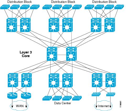
Campus Designs Tested
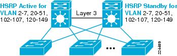
The specific designs chosen to be tested were determined based on the hierarchical design recommendations as outlined in Designing a Campus Network for High Availability. All of the tested designs utilize a Layer 3 routed core to which the other architectural building blocks are connected, as shown in Figure 2.
Figure 2 Campus Design
Within the structured hierarchical model, the following four basic variations of the distribution building block were tested:
•
•
•
•
Both component failure and component restoration test cases were completed for each of these four specific distribution designs.
In addition to the four basic distribution configurations tested, two additional tests were run comparing variations on the basic L2 distribution block design. The first using the L2 access running Rapid PVST+ distribution block design, compared GLBP with HSRP as the redundant default gateway protocol. The second case compared the recovery of the Rapid PVST+ distribution block design with a Spanning Tree loop and with no loop.
Note
The analysis of the observed results is described in the following three sections.
•
•
•
Each of the specific test cases were performed using meshed end-to-end data flows passing through the entire campus, but the analysis for each test case has been done separately. One of the major advantages of the hierarchical design is the segregation of fault domains. A failure of a node or a link in the core of the network results in the same convergence behavior and has the same impact on business applications, independent of the specific design of the distribution block. Similarly, a failure in the distribution block is isolated from the core and can be examined separately.
Note
Testing Procedures
The configuration of the test network, test traffic, and test cases were chosen to simulate as closely as possible real customer traffic flows and availability requirements. The test configuration is intended to demonstrate the effectiveness of Cisco best practices design in a real world environment.
Testing assumptions were the following:
•
•
•
•
Test Bed Configuration
The test bed used to evaluate failure recovery consisted of a Layer 3 routed core with attached distribution and server farm blocks. The core and distribution switches used were Cisco Catalyst 6500s with Supervisor 720a engines. The access layer consisted of 39 switches dual-attached to the distribution layer. The following configurations were used:
•
•
•
•
•
–
–
–
–
–
–
–
–
•
•
•
Test Traffic
180 Chariot endpoint servers were used to generate traffic load on the network during tests as well as gather statistics on the impact of each failure and recovery event.
Note
The Chariot endpoints were configured to generate a mix of enterprise application traffic flows based on observations of actual Cisco customer networks.
The endpoints attached to each of the 39 access and data center switches were configured to generate the following unicast traffic:
•
•
(HTTP, tn3270), POP3, HTTP, DNS, and WINS.All traffic was marked according to current Enterprise QoS Solution Network Design Guide v1.3 recommendations—http://www.cisco.com/en/US/docs/solutions/Enterprise/WAN_and_MAN/QoS_SRND/QoS-SRND-Book.html—and the generated traffic load was sufficient to congest select uplinks and core infrastructure.
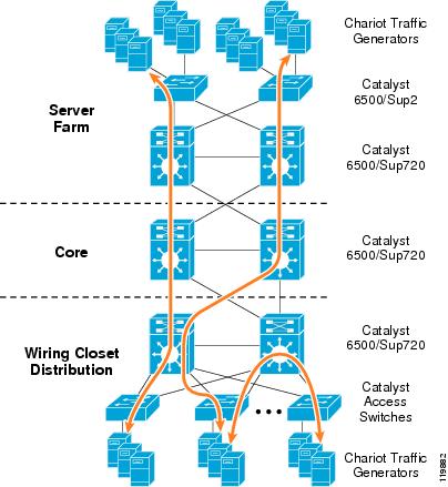
Traffic flows were defined such that the majority of traffic passed between the access layer and the data center using the core of the network. A subset of VoIP streams were configured to flow between access switches using the distribution switch, as shown in Figure 3.
Figure 3 Test Bed with Sample Traffic Flows
In addition to the unicast traffic, each access switch was configured with 40 multicast receivers receiving a mix of the following multicast streams:
•
•
•
•
•
•
•
•
All multicast MoH is marked as Express Forwarding (EF) and all other multicast traffic is marked as Differentiated Services Code Point (DSCP)14 (AF13).Methodology Used to Determine Convergence Times
In keeping with the intent of this testing to aid in understanding the impact of failure events on application and voice traffic flows in a production network, the convergence results recorded in this document are based on measurements of actual UDP and TCP test flows. The convergence time recorded for each failure case was determined by measuring the worst case packet loss on all of the active G.711 voice streams during each test run.
Note
This worst case result recorded is the maximum value observed over multiple iterations of each specific test case, and represents an outlier measurement rather than an average convergence time. The use of the worst case observation is intended to provide a conservative metric for evaluating the impact of convergence on production networks.
Each specific test case was repeated for a minimum of three iterations. For fiber failure tests, the three test cases consisted of the following:
•
•
•
•
•
•
Additionally, for those test cases involving an access switch, each of the three sub-cases was run multiple times; once for each different access switch type (please see above for list of all access switches tested).
In addition to the maximum period of voice loss, mean opinion scores (MOS) for all voice calls were recorded, as well as network jitter and delay.
Test data was also gathered on the impact of network convergence on active TCP flows. In all test cases, the period of loss was small enough that no TCP sessions were ever lost. The loss of network connectivity did temporarily impact the throughput rate for these traffic flows. It is also worth noting that the "interval of impact", or the period of time that the TCP flows were not running at normal throughput rates, was larger than the period of loss for the G.711 UDP flows. As was expected, packet loss during convergence triggered the TCP back-off algorithm. The time for the TCP flows to recover back to optimal throughput was equal to [Period_Of_Packet_Loss + Time Required For TCP Flow Recovery].
Layer 3 Core Convergence—Results and Analysis
Description of the Campus Core
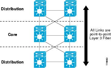
The campus core provides the redundant high speed connection between all of the other hierarchical building blocks. A fully meshed core design using point-to-point Layer 3 fiber connections as shown in Figure 4 is recommended to provide optimal and deterministic convergence behavior.
Figure 4 Core Topology
The core of the network under test consisted of paired Cisco Catalyst 6500/Supervisor 720s with redundant point-to-point 10 Gigabit Ethernet (GigE) links between each distribution switch and the core switches. The core switches were linked together with a point-to-point 10GigE fiber. While this link is not strictly required for redundancy in a unicast-only environment, it is still a recommended element in the campus design. In certain configurations, this link is used for multicast traffic recovery. It is also necessary if the core nodes are configured to source default or summarized routing information into the network
In addition to the two distribution blocks shown in Figure 4 that carried test traffic, additional sets of distribution switches and backend routers were connected to the core, simulating the connection of the campus to a enterprise WAN. No test traffic was configured to be forwarded over this portion of the test network, and it was used only to inject additional routes into the campus. In total, the campus under test had 3572 total routes.
Core-Switch-2# show ip route summary
IP routing table name is Default-IP-Routing-Table(0)
Advantages of Equal Cost Path Layer 3 Campus Design
In the recommended campus design, every node, both distribution and core, has equal cost path forwarding entries for all destinations, other than for locally-connected subnets. These two equal cost paths are independent of each other, and in the event of any single component failure, link or node, this means that the surviving path is guaranteed to provide a valid route. In the event of any single component failure, every switch in this design is able to successfully recover from and route around any next hop failure.
Because each node has two paths and is able to recover from any link failure, no downstream device ever needs to re-calculate a route because of an upstream failure, because the upstream device still always has a valid path. The architectural advantage of the meshed Layer 3 design is that in the event of any single component failure, all route convergence is always local to the switch and never dependent on routing protocol detection and recovery from indirect link or node failure.
In a Layer 3 core design, convergence times for traffic flowing from any distribution switch to any other distribution switch are primarily dependent on the detection of link loss on the distribution switches. On GigE and 10GigE fiber, link loss detection is normally accomplished using the Remote Fault detection mechanism implemented as a part of the 802.3z and 802.3ae link negotiation protocols.
Note
Once the distribution switch detects link loss, it processes a link down event that triggers the following three-step process:
1.
2.
adjacencies for those routes affected.
3.
In the equal cost path core configuration, the switch has two routes and two associated hardware CEF forwarding adjacency entries. Before a link failure, traffic is being forwarded using both of these forwarding entries. Upon the removal of one of the two entries, the switch begins forwarding all traffic using the remaining CEF entry. The time taken to restore all traffic flows in the network is dependent only on the time taken to detect the physical link failure and to then update the software and associated hardware forwarding entries.
The key advantage of the recommended equal cost path design is that the recovery behavior of the network is both fast and deterministic.
The one potential disadvantage in the use of equal cost paths is that it limits the ability to engineer specific traffic flows along specific links. Overriding this limitation is the ability of the design to provide greater overall network availability by providing for the least complex configuration and the fastest consistent convergence times.
Note
Layer 3 Core Convergence Results—EIGRP and OPSF
Failure Analysis
The campus core contains the following three basic component failure cases to examine:
•
•
•
Table 1 summarizes the testing results
In the recommended campus core design, all nodes have redundant equal cost routes. As a direct result, the recovery times for single component failures are not dependent on routing protocol recovery to restore traffic flows. In the event of a link failure, each node is able to independently re-route all traffic to the remaining redundant path. In the event of node failure, the impacted neighbor switches detect the loss when the interconnecting link fails and are thus able to again independently re-route all traffic to the remaining redundant path.
Two of the three failure cases—failure of a core node itself, and failure of any fiber connecting a distribution-to-core switch—are dependent on equal cost path recovery. In the third case—failure of the core-to-core fiber link—there is no loss of an active forwarding path and thus no impact on unicast traffic flows in the event of its loss. In all three cases, the network is able to restore all unicast traffic flows without having to wait for any routing protocol topology updates and recalculation.
The failure of the fiber between the core switches normally has no direct impact on unicast traffic flows. Because of the fully meshed design of the core network, this link is only ever used for unicast traffic in a dual failure scenario. While this link is not strictly required for redundancy in a unicast-only environment, it is still a recommended element in the campus design. In certain configurations, this link is used for multicast traffic recovery. It is also necessary if the core nodes are configured to source default or summarized routing information into the network.
Although the ability of the network to restore traffic flows because of component failure is independent of the routing protocol used, routing protocol convergence still takes place. EIGRP generates topology updates and OSPF floods link-state advertisements (LSAs) and runs Dijkstra calculations. To minimize the impact these events have on the network, Cisco recommends that the campus design follow good routing protocol design guidelines. Please see the HA campus and Layer 3 access design guides for more information.
The time to recovery for events resulting in equal cost path recovery is dependent on:
•
•
To achieve the rapid detection of link loss, which is necessary to achieve the convergence times recorded above, it is necessary to ensure that 802.3z or 802.3ae link negotiation remains enabled for all point-to-point links. The default behavior for both CatOS and Cisco IOS is for link negotiation to be enabled. Disabling link negotiation increases the convergence time for both upstream and downstream flows.
CatOS:
set port negotiation [mod/port] enable
show port negotiation [mod[/port]]
Cisco IOS:
int gig [mod/port]
 [no] speed nonegotiate
Restoration Analysis
The convergence cases for link and device restoration are identical with those for the failure scenarios:
•
•
•
Table 2 summarizes the test results.
As the results in Table 2 demonstrate, link and node restoration in the Layer 3 campus normally has minimal impact to both existing and new data flows. Activation or reactivation of a Layer 3 forwarding path has this inherent advantage; the switch does not forward any traffic to an upstream or downstream neighbor until the neighbor has indicated it can forward that traffic. By ensuring the presence of a valid route before forwarding traffic, switches can continue using the existing redundant path while activating the new path.
During the activation of a newly activated link, the switches proceed through EIGRP/OSPF neighbor discovery and topology exchange. As each switch learns these new routes, it creates a second equal cost entry in the routing and CEF forwarding table. In a redundant design, this second equal cost forwarding is added without invalidating the currently existing entries. The switch continues to use the existing hardware forwarding entries during the routing protocol update process, and does not lose any data because of the new route insertion.
Unlike the component failure case described above, in which route removal is independent of routing protocol convergence, each campus switch is directly dependent on the routing protocol to install new routes upon the activation of a new link or node. The network is not dependent on the speed with which these new routes are inserted, so the speed with which EIGRP and OSPF propagates and inserts the new routes is not a critical metric to track. However, as with the failure case, it is necessary to follow recommended design guidelines to ensure that the route convergence process has minimal impact on the network as a whole.
In most environments, activation of a link or a switch in a redundant Layer 3 campus design occurs with no impact. However, in the transition period during insertion of a new route—either a better path route or second equal cost route—it is possible in a highly oversubscribed network that a packet from an existing flow sent over the new active path may arrive before one previously transmitted over the older path, and thus arrive out of sequence. This occurs only if the load on the original path is such that it experiences heavy congestion with resulting serialization delay.
During testing using a highly oversubscribed (worst case) load, we observed that packet loss for a voice stream because of re-ordering was experienced by less than 0.003 percent of the active voice flows. The very low level of packet loss and low level of associated jitter produced by the activation of a second link and the dynamic change in the forwarding path for voice streams did not have a measurable impact on recorded MOS scores for the test streams. Activation of a new link or node in a redundant Layer 3 campus design can be accomplished with no operational impact to existing traffic flows.
Layer 2 Access with Layer 3 Distribution Convergence—Results and Analysis
This section includes the following topics:
•
•
•
•
•
•
Test Configuration Overview
The set of switches comprising the distribution layer and all the attached access switches is often called the distribution block. In the hierarchical design model, the distribution block design provides for resilience for all traffic flowing between the devices attached to the access switches, as well as providing redundant connections to the core of the campus to provide resiliency for all traffic entering and leaving this piece of the campus.
The following two specific configuration cases exist within the standard distribution block design:
•
•
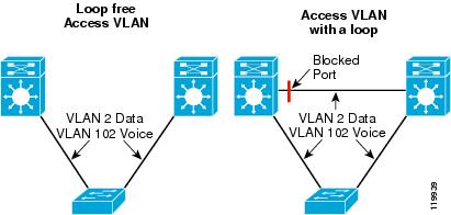
Figure 5 Standard Distribution Building Block with and without a Layer 2 Loop
For each of these two basic cases, there are additionally a number of specific configuration variations possible because of the variety of default gateways, Spanning Tree versions, and routing protocols that can be utilized. The five test configurations examined in this section were chosen to demonstrate the differences between the possible configuration variations. (See Table 3.)
For each of the five test configurations, the following five basic failure tests were performed:
1.
distribution switch2.
3.
4.
5.
Test cases 1 and 2 were run multiple times once for each different access switch type and consisted of the following three failure scenarios:
•
•
•
For each failure test, a complimentary switch restart or link activation test was done to examine the impact of an operations team rebooting or replacing a failed component.
The results reported below were the worst case observations made during the multiple test iterations. In the first four test cases, the physical topology, VLAN, and all other configuration remained consistent throughout the tests. In the fifth test case, the voice and data VLANs were configured to pass across a trunk connecting the two distribution switches. Please see below for description and configuration of the distribution and access switches.
Note
Description of the Distribution Building Block
The standard distribution building block consists of a pair of distribution switches and multiple access switches uplinked to both distribution switches, as shown in Figure 6.
Figure 6 Standard Distribution Building Block without Layer 2 Loops (Test Configurations 1 Through 4)
Within the confines of the basic physical topology, details of the configuration for the distribution building block have evolved over time. The following specific design options were utilized for the first four test network configurations:
•
•
•
The voice and data VLANs are unique for each access switch, and are trunked between the access switch and the distribution switches but not between the distribution switches. The link between the distribution switches was configured as Layer 3 point-to-point. Cisco best practices design recommends that no VLAN span multiple access switches. The use of a common wireless VLAN bridged between multiple access switches has been recommended as one mechanism to support seamless roaming for wireless devices between access points (APs). The introduction of the Wireless LAN Switching Module (WLSM) provides a scalable architecture to support fast roaming without the need for a common Layer 2 VLAN for the APs.
Spanning Tree root and HSRP primary gateway is assigned to distribution switch 1 for all VLANs.
A default gateway protocol, either HSRP or GLBP, was configured for each of the unique access data and voice VLANs. In the test network, all of the active HSRP gateways and the associated root bridge for each VLAN were configured on distribution switch 1.
Two distinct design approaches are usually used when assigning default gateway location. One approach alternates HSRP gateways between the two distribution switches for voice and data, or odd and even VLANs as a mechanism to load share upstream traffic. An alternative approach assigns one of the distribution switches as the active gateway for all VLANs as a means to provide consistent configuration and operational behavior. For those environments with a load balancing requirement, Cisco recommends that GLBP be utilized rather than alternating HSRP groups, because it provides for effective load balancing upstream traffic. For those environments requiring a more deterministic approach, Cisco recommends assigning all HSRP groups to a single distribution switch.
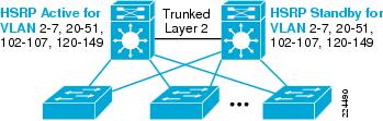
The network configuration was changed for the fifth test case as shown in Figure 7.
Figure 7 Figure 7 Distribution Building Block with Layer 2 Loops (Test Configuration 5)
The network used for the fifth configuration case differs from that described above only in that all voice and data VLANs were trunked on the 10GigE fiber between the two distribution switches. Dedicated voice and data VLANs were still configured for each access switch, and the root bridge and HSRP active node were configured on distribution switch 1 for all VLANs.
In order to maximize the effectiveness of the dynamic default gateway load balancing mechanism offered by GLBP, Spanning Tree was configured to block on the port attached to the distribution-to-distribution link. By forcing this link to block both of the access-to-distribution links for all VLANs, the network was able to load share traffic in both the upstream and downstream direction during normal operation. This configuration is shown by the following example:
Distribution-Switch-2#sh run int ten 4/3interface TenGigabitEthernet4/3description 10GigE trunk to Distribution 1 (trunk to root bridge)no ip addressload-interval 30mls qos trust dscpswitchportswitchport trunk encapsulation dot1q switchport trunk native vlan 900 switchport trunk allowed vlan 2-7,20-51,102-107,120-149 spanning-tree cost 2000 << Increase port cost on trunk to root bridge
Note
For a more detailed description and explanation of the design recommendations used in these tests, please see Designing a Campus Network for High Availability.
Configuration 1 Results—HSRP, EIGRP with PVST+
Failure Analysis
Configuration 1 has the following characteristics:
•
•
•
Table 4 summarizes the testing results.
Uplink Fiber Fail to Active HSRP Distribution Switch
Upstream Convergence
The restoration time for upstream traffic flows is primarily determined by the configuration of HSRP timers. In a normal state, all traffic sourced from end stations is bridged upstream to the active HSRP peer destined for the virtual HSRP MAC address. On failure of the uplink to the active HSRP peer, the access switch flushes all CAM entries associated with that link from its forwarding table, including the virtual HSRP MAC.
At the same time, the standby HSRP peer starts to count down to the configured dead timer because it is no longer receiving hellos from the active peer. After the loss of three hellos, the standby peer transitions to active state, transmits gratuitous ARPs to pre-populate the access switch CAM table with the new location of the virtual HSRP MAC address, and then begins to accept and forward packets sent to the virtual HSRP MAC address. (See Figure 8.)
Figure 8 Uplink Fiber Fail to Active HSRP Distribution Switch—Upstream Convergence
The recovery times recorded for these specific test cases were obtained using 250 msec hello and 800 msec dead interval HSRP timers. The 900 msec upstream loss is a worst case observation that occurs only in a specific failure scenario. Fiber loss between two switches can occur either as a loss of a single fiber of the pair or as the loss of both fibers in the pair simultaneously. In the case of a failure of only the fiber connected to the receive port on the active distribution switch, there exists a small window of time in which the switch is able to transmit HSRP hello frames but is unable to receive inbound traffic before remote fault detection shuts down the interface.
In the case of loss of the transmit fiber from the active switch, the opposite effect is observed. HSRP hellos are not sent but data sent to the core is still received, resulting in a reduced period of loss. While synchronization of the single fiber failure and the transmission of an HSRP update can increase the worst case convergence, the 900 msec test result was an outlier case that only slightly skewed the overall average convergence time of 780 msec.
While the loss of the active HSRP peer also means the loss of the Spanning Tree root bridge, this does not result in any traffic loss. The Spanning Tree topology as configured has no loops and no need to transition any ports from blocking state. The loss of the active root bridge does trigger a new root bridge election, but in an 802.1d implementation this has no impact on active port forwarding.
Design Tip—While it is possible to reduce the recovery time for the upstream portion of a voice or data traffic flow by reducing the HSRP hello and dead interval, Cisco recommends that the HSRP dead time match the recovery time for the downstream portion of the flow.These test cases were completed using an 800 msec dead time, which corresponded to the observed EIGRP downstream recovery for the voice VLAN. Reducing the HSRP timers too much may result in network instability in the event of very high CPU loads being experienced on the distribution switches. The 250/800 msec configuration was verified to operate successfully with CPU loads of 99 percent in this reference test topology.
Downstream Convergence
The restoration time for downstream traffic flows in a loop-free configuration is primarily determined by routing protocol convergence. (See Figure 9.)
Figure 9 Uplink Fiber Fail to Active HSRP Distribution Switch—Downstream Convergence
On detection of the fiber failure, the switch processes the following series of events to restore connectivity:
1.
2.
3.
instance are also marked down.4.
5.
6.
7.
8.
routing table.9.
10.
Because the distribution switch does not have an equal cost path or feasible successor to the lost networks, it is necessary for EIGRP to initiate a routing convergence to restore traffic flows.
Note
The ability of the query process to complete quickly is also dependent on the ability of the originating and receiving switches to process the EIGRP query. To ensure a predictable convergence time, you also need to make sure that the network is protected from anomalous events such as worms, distributed denial of service (DDoS) attacks, and Spanning Tree loops that may cause high CPU on the switches.
Note
Table 5 Recommendations for VLAN Assignments
Wired_Voice_VLAN
7
Wireless_Voice_VLAN
57
Wired_Data_VLAN
107
Wireless_Multicast_VLAN
157
Not all VLANs trunked on a specific interface converge at the same time. Cisco IOS throttles the notifications for VLAN loss to the routing process (EIGRP/OSPF) at a rate of one every 100 msec. As an example, if you configure six VLANs per access switch, upon failure of an uplink, fiber traffic on the sixth VLAN converges 500 msec after the first.
Uplink Fiber Fail to Standby HSRP Distribution Switch
Upstream Convergence
Failure of the standby HSRP distribution switch has no impact on upstream traffic, because all traffic is being processed by the active switch.
Downstream Convergence
The impact on downstream traffic is identical to the failure of an uplink to the active distribution switch. The core switches continue to forward traffic to both distribution switches, and the recovery of the downstream data path is dependent on the re-route from one distribution switch to the other.
Active HSRP Distribution Switch Failure
Upstream Convergence
The recovery mechanism for upstream traffic after a complete distribution switch failure operates exactly like the fiber failure case. Failure of the switch does increase the recovery load placed on the standby switch because of the recovery for multiple HSRP addresses simultaneously. However, within the bounds of these test cases, no impact to recovery time because of this increased processing overhead was observed.
Downstream Convergence
Restoration of downstream traffic after a distribution switch failure is achieved using Layer 3 equal cost recovery in the core switches. As described in the results section for the Layer 3 core design above, both core switches have redundant routes to all access subnets using the two distribution switches. In the event either distribution switch fails, the core nodes start to forward all traffic downstream through the remaining distribution switch with an observed period of less than 200 msec loss.
Standby HSRP Distribution Switch Failure
The failure of the standby HSRP distribution switch has no impact on upstream traffic flows. The failure for downstream flows is identical to that as described for the active HSRP switch above.
Inter-Switch Distribution Fiber Fail
The failure of the Layer 3 connection between the distribution switches has no impact on any upstream or downstream traffic flows. This link is designed to be used only to provide recovery for traffic within the distribution block in the event of an uplink failure. Because the subnet for this link is contained within the summarized distribution block address range, no EIGRP topology updates are sent to the core.
Restoration Analysis
Configuration 1 has the following characteristics:
•
•
•
Table 6 summarizes the test results.
Uplink Fiber Restore to Active HSRP
Activation of the fiber connection between an access switch and a distribution switch does not normally cause loss of data. Upon activation of the link, the primary distribution switch triggers a root bridge re-election and takes over the active role as root. This process results in a logical convergence of the Spanning Tree but does not cause the change in forwarding status of any existing ports, and no loss of forwarding path occurs.
In addition to the Spanning Tree convergence, once the HSRP preempt delay timer expires, the primary HSRP peer initiates a take-over for the default gateway. This process is synchronized between the distribution switches so no packet loss should result. The transition of the Spanning Tree state for the voice and data VLANs also triggers the insertion of a connected route into the routing table. Once the connected route is inserted, the switch starts forwarding packets onto the local subnet.
Uplink Fiber Restore to Standby HSRP
As in the case of the primary distribution switch, activation of the uplink fiber to the standby distribution switch does not impact existing voice or data flows. In this case, neither root bridge nor HSRP gateway recovery needs to occur. The switch inserts a connected route for the voice and data VLANs and starts forwarding traffic. As in the case above, this should not noticeably impact any active data flows.
Active HSRP Distribution Switch Restoration
The activation of a distribution switch has the potential to cause noticeable impact to both the upstream and downstream component of active voice flows. If HSRP is configured to preempt the role of active gateway, upon activation of the primary distribution switch, root bridge, and HSRP higher priority, there may be a period of time in which the switch has taken the role of default gateway but has not established EIGRP neighbors to the core. The switch is not able to forward traffic it has received from the access subnets, which results in a temporary routing black hole.
A number of methods exist to avoid this problem. One recommendation is to configure an HSRP preempt delay that is large enough to ensure both that all line cards and interfaces on the switch are active and that all routing adjacencies have become active. The following configuration example demonstrates this recommendation:
interface Vlan20description Voice VLAN for 3550ip address 10.120.20.2 255.255.255.0ip verify unicast source reachable-via anyip helper-address 10.121.0.5no ip redirectsip pim query-interval 250 msecip pim sparse-modeload-interval 30standby 1 ip 10.120.20.1standby 1 timers msec 250 msec 800standby 1 priority 150standby 1 preempt delay minimum 180 << Configure 3 minute delaystandby 1 authentication eseTuning HSRP can avoid the problem of upstream loss; however, activation of the distribution node in a heavily-loaded environment can also result in loss of downstream traffic. Once the distribution node advertises the distribution block routes to the core switches, it immediately begins receiving traffic for all of its connected subnets.
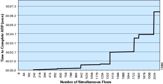
To forward this traffic, the distribution switch needs to determine the next hop adjacency, the Address Resolution Protocol (ARP) table entry, for each flow. The recovery time for this process is dependent on the number of flows, the ability of the end stations to respond to ARP requests, and the ARP throttling behavior of the distribution switch.
In order to protect against DoS attacks, either intentional or the side effect of a scanning worm, all of the Cisco Catalyst switches have implemented rate throttling mechanisms on ARP processing. Although these throttles protect the switch in the event of a DoS attack, they cannot distinguish between a sudden flood of DoS traffic and a sudden flood of valid traffic. In both cases, the switch throttles the rate of ARP requests generated. In a large campus environment with a high volume of active flows, a rebooted distribution switch experiences a sudden burst of ARP activity that is dampened by the inherent DoS protection mechanisms.
Figure 10 shows the impact of DoS protection on router performance.
Figure 10 Impact of DoS Protection
Number of Simultaneous Flows
Although this behavior can have a short term impact on traffic flows, if a switch is rebooted during a period of high activity, the overall advantages the DoS protection mechanisms provide far outweigh the cost.
Standby HSRP Distribution Switch Restoration
The reboot of a standby switch can have a similar potential impact on downstream flows as described above. Managing scheduled reboots of the distribution switches mitigates any potential impact. HSRP and Spanning Tree state do not change as a result of the reboot, so upstream flows are not impacted.
Inter-Switch Distribution Fiber Restore
Activation of the link between distribution switches will not impact active traffic flows. As the distribution block routes are summarized up to the core the activation of a new subnet will not result in a topology update.
Configuration 2 Results—HSRP, EIGRP with Rapid-PVST+
Failure Analysis
Configuration 2 has the following characteristics:
•
•
•
Test Results Summary
Table 7 summarizes the test results.
Impact of Conversion to 802.1w
The convergence characteristics after link or node failure for the distribution block using 802.1w as the Spanning Tree protocol are the same as for the same topology configured with 802.1d. In the recommended design, all Layer 2 loops have been removed from the network, and this design makes no use of the improvement in convergence time offered by 802.1w over 802.1d. As described above, traffic flow recovery is accomplished either through HSRP, EIGRP, or an equal cost path failover, and at no time is a Layer 2 convergence necessary to restore traffic flows.
spanning-tree mode rapid-pvst  <<< Enable 802.1w per VLAN spanning tree
spanning-tree loopguard default
no spanning-tree optimize bpdu transmission
spanning-tree extend system-id
spanning-tree vlan 2-7,20-51,102-149,202-207,220-249,900 priority 28672
Restoration Analysis
Configuration 2 has the following characteristics:
•
•
•
Test Results Summary
Table 8 summarizes the test results.
Impact of Conversion to 802.1w
The use of 802.1w rather than 802.1d has a minor but measurable impact on voice traffic during the activation of a switch or link, because of differences in the way ports transition to an active forwarding state between the two protocols. When the primary switch (configured with preferred root bridge) is rebooted or reconnected to the access switch, a Spanning Tree topology change needs to occur. The newly-activated root bridge begins transmitting Bridge Protocol Data Unit (BPDU) frames with a lower priority than the secondary root, and triggers a movement of the root bridge and an associated recalculation of the Layer 2 topology.
In the 802.1d topology, the transition to the new topology does not trigger any currently active ports to transition to blocking state, because the topology is loop free and as a result, traffic continues to be bridged to the secondary distribution switch without any loss. Because the active HSRP gateway remains on the secondary switch for an additional 180 seconds because of the use of HSRP preempt, the port transition on the root switch to forwarding does not impact active traffic flows.
In the 802.1w topology, when the primary switch is reconnected, the uplink port on the access switch and the downlink port on the primary switch come up in designated blocking state. When the access switch receives the better root BPDU from the newly-activated primary distribution switch, it begins the topology transition by first blocking all of its non-edge designated ports (all ports not configured for PortFast). Once all non-edge ports are blocked, the access switch can then complete negotiation with the new root bridge, and safely transition the associated uplink port to forwarding state without causing a Spanning Tree loop. Once the new root port has moved to forwarding state, the access switch then completes the same negotiation process on each of its now blocked designated ports, and if necessary, transitions them to forwarding state as well.
The sync step of blocking all designated ports during the transition to a new root port is a necessary step in the 802.1w Spanning Tree topology calculation, but as a side effect results in the temporary blocking of the uplink to the secondary distribution switch. Because the secondary distribution switch is still the active HSRP gateway, this results in a loss of the active forwarding path for all upstream traffic. Downstream traffic is also impacted by the same sync process. Traffic passing from the core through the secondary distribution switch is also blocked for the period of port negotiation and transition back to forwarding state.
Note
http://www.cisco.com/application/pdf/en/us/guest/tech/tk621/c1501/ccmigration_09186a0080174993.pdf
Configuration 3 Results—HSRP, OSPF with Rapid-PVST+
Failure Analysis
Configuration 3 has the following characteristics:
•
•
•
Test Results Summary
Table 9 summarizes the test results.
Impact of Conversion to OSPF
In a redundant campus design, the need for the network to recalculate a new route to any destination is limited to a single case: the failure of the uplink between an access switch and the distribution switch. In all other failure scenarios, the recovery of the forwarding path is dependent either on default gateway (HSRP) redundancy or on equal cost path re-route. In the case of an access switch uplink failure, the network needs to initiate a re-route because no redundant path can exist. OSPF convergence for this failure case tends to be worse than EIGRP because of inherent differences in the operation of the two protocols.
Upon failure of the access uplink, the distribution switch needs to trigger a re-route in the network. If the network is configured to advertise summarized routes into the core (that is, the distribution block is configured as a standalone OSPF area), then the re-route for this failure is across the link connecting the two distribution switches. Conversely, if the campus as a whole is configured as a single area with no route summarization, then the re-route occurs on the core nodes, once they determine the loss of the downstream route from one distribution switch. The behaviors of EIGRP and OSPF are consistent up to this point; both protocols initiate a re-route, either within the summarized distribution block or in the core if no summarization is configured.
The time required for EIGRP to complete this re-route is largely dependent on the efficiency of the query and response processing. In a well-summarized design, the query process is very efficient and has deterministic bounds on convergence time.
Note
Compared to EIGRP, the time required for OSPF to converge is bounded by the time necessary to exchange LSA updates, the time to calculate the shortest path first (SPF) tree, and by the presence of throttle mechanisms on the rate at which both of these events can happen.
In the OSPF configuration, the actual re-route is not triggered by hello loss and dead timer expiration, but by 802.3z or 802.3ae remote fault detection triggering the interface down condition. Upon notification of the link down event, the OSPF process starts the LSA propagation throttle timer. Rather than immediately send updates, the router waits a period of time (0.5 seconds by default) to buffer LSAs before transmission. After transmission of LSAs and upon receipt of any new LSA updates, a second throttle timer, the SPF timer, is started.
Upon expiration of this second timer, the SPF calculation is performed, new routes if any are populated into the routing table, and associated CEF forwarding entries are created. The LSA propagation and the SPF throttle timer are necessary to reduce the number of times the SPF calculation is performed in response to a single network event, and thus to dampen incorrect or incomplete route updates because of partial topology information.
The 1600 msec convergence times recorded during this testing result from the total time OSPF takes to detect link failure, propagate LSAs, calculate SPF, and insert new routes including the time taken by the throttle timers. For the purposes of these test cases, the SPF timers on all nodes in the network were reduced to 1 second, as shown in the following configuration.
router ospf 100
 router-id 10.122.0.3
 log-adjacency-changes
timers spf 1 1 <<< Reduce SPF Timers to 1 secondarea 120 stub no-summary area 120 range 10.120.0.0 255.255.0.0 network 10.120.0.0 0.0.255.255 area 120 network 10.122.0.0 0.0.255.255 area 0As of Cisco IOS release 12.2(17b) SXA, the configuration syntax for SPF tuning changed with the introduction of sub-second SPF timers.
router ospf 100
 router-id 10.122.0.3
 log-adjacency-changes
timers throttle spf 1000 1000 1000 <<< One second SPF using 12.2(17b)SXA and later IOSarea 120 stub no-summary area 120 range 10.120.0.0 255.255.0.0 network 10.120.0.0 0.0.255.255 area 120 network 10.122.0.0 0.0.255.255 area 0
Note
http://www.cisco.com/en/US/docs/ios/12_2t/ip_route/command/reference/p2ftospf.html
Restoration Analysis
Configuration 3 has the following characteristics:
•
•
•
Test Results Summary
Table 10 summarizes the test results.
Impact of Conversion to OSPF
The behavior of the network is identical when activating a link or restarting a node in the redundant campus design, independent of the routing protocol used (OSPF or EIGRP). The cases where traffic may be lost are the same as those described in configuration tests 1 and 2 above. 802.1w sync processing results in minimal but noticeable loss during any root bridge topology changes, and the ARP DoS protection features cause the same traffic outages under the same conditions as described above.
Configuration 4 Results—GLBP, EIGRP with Rapid-PVST+
Failure Analysis
Configuration 4 has the following characteristics:
•
•
•
Test Results Summary
Table 11 summarizes the test results.
Impact of Conversion to GLBP
The worst case restoration times for fiber and/or node failure when using the same timer configuration are equivalent for both HSRP and GLBP. In both cases, the failover mechanism is dependent on the loss of neighbor notification and the takeover of the virtual MAC address. The following two differences are noticed in a GLBP implementation.
•
•
The nature of the dynamic GLBP load balancing algorithm ensures that only one half of the end stations use each distribution switch as the default gateway at any one point in time. Worst case convergence is not improved through the use of GLBP because half of the stations experience a traffic loss for upstream traffic and half the workstations experience traffic loss for downstream flows. Statistically, there is no correlation between which stations are affected for either the upstream or downstream flows, and in the worst case, every end station may experience an outage during a network convergence.
Note
Restoration Analysis
Configuration 4 has the following characteristics:
•
•
•
Test Results Summary
Table 12 summarizes the test results.
Impact of Conversion o GLBP
Changing the default gateway redundancy protocol has no impact on device activation. Any loss in the network is attributed to packet loss, either because of the 802.1w sync process or because of ARP DoS protection mechanisms affecting recovery during very high volume traffic.
Note
Configuration 5 Results—GLBP, EIGRP, Rapid-PVST+ with a Layer 2 Loop
Failure Analysis
Configuration 5 has the following characteristics:
•
•
•
Test Results Summary
Table 13 summarizes the test results.
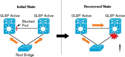
Impact of Introduction of a Layer 2 Loop in Access VLAN
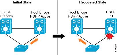
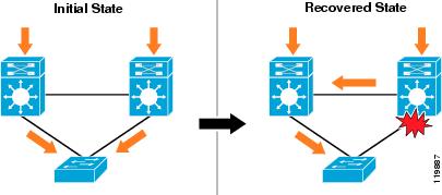
The introduction of a Layer 2 Spanning Tree loop, spanning the VLAN's across a trunk between the two distribution switches, reduces the period of time to recover both upstream and downstream traffic flows in the event of a single fiber failure, as compared to the loop-free design. In the Layer 2 looped configuration, 802.1w recovery of a lost link in the topology avoids the need for HSRP and EIGRP to converge, as shown in Figure 11.
Figure 11 802.1w Recovery in Layer 2 Looped Configuration
Before the introduction of 802.1w, both HSRP and EIGRP were able to converge much faster than 802.1d was able to detect the failed link and un-block a redundant link. By introducing the loop into the network, we change the following two features of the design:
•
•
Introducing a looped Layer 2 topology has no impact on the network convergence times in the event of distribution switch failures. In this event, the redundant Layer 2 path no longer exists and the network depends on GLBP for default gateway recovery and depends on equal cost path recovery in the core for downstream traffic recovery.
Note
Restoration Analysis
Configuration 5 has the following characteristics:
•
•
•
Test Results Summary
Table 14 summarizes the test results.
Impact of Introduction of a Layer 2 Loop in Access VLAN
Introducing a Spanning Tree loop into the access VLAN does not change the impact of device activation on active traffic flows. Any loss in the network is still attributed to packet loss, either because of the 802.1w sync process or because of ARP DoS protection mechanisms affecting recovery during very high volume traffic.
Note
Layer 3 Routed Access with Layer 3 Distribution Convergence—Results and Analysis
Layer 3 Routed Access Overview
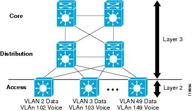
An alternative to the standard Layer 2 access distribution building block design is a routed access, or Layer 3 to the edge implementation. as shown in Figure 12.
Figure 12 Layer 3 Routed Access Implementation
VLAN Voice 102, 103 and 149
In this design, the access switch is configured as a full Layer 3 routing node participating in the campus routing protocol. The Layer 2/3 demarcation is moved from the distribution switch to the access switch at the edge of the campus network. Traffic from the local voice and data VLANs is routed rather than bridged upstream to the distribution switch.
This design seems at first to be very different from the standard distribution building block, but is in many ways very similar. In both designs, each access switch is configured with a dedicated voice and data subnet (VLAN). In both designs, all links between routing nodes are configured as point-to-point. The primary difference is the location of the default gateway.
In the classical design, the default gateway resides in the distribution node, and the links between the access switch and the distribution switch are configured to extend the data and voice VLANs up to the distribution router. In the Layer 3 access design, the default gateway resides on the access switch, and the uplinks are configured as dedicated point-to-point subnets using /30 or /31 addressing.
EIGRP Results
EIGRP Failure Results
There are fewer failure cases to consider in a Layer 3 access design. By moving the Layer 2/3 demarcation from the distribution to the access switch, certain failure scenarios are no longer relevant. There is no longer a need for a redundant default gateway mechanism because the default gateway function is now distributed to the edge switches. HSRP/GLBP tuning and convergence times do not impact campus design decisions. Spanning Tree instances run in a single switch and do not impact convergence times. The routed access campus is entirely dependent on the L3 convergence behavior of the campus switches and on the convergence behavior of the routing protocols deployed.
Running Layer 3 in the access also results in dynamic load balancing of all upstream and downstream traffic flows. Equal cost routes from the access to the distribution split the load upstream towards the core between the two uplinks. Equal cost paths on each of the core nodes split the load between the two distribution switches, which results in a symmetrical load on the return path downstream from the distribution to the access. This load balanced or symmetrical behavior means that in a redundant Layer 3 campus design, any specific node or link failure only affects at most approximately one half of the traffic flows in the network. The failure of any single path because of link or node failure affects only the flows using that specific path.
Note
In the Layer 3 access design, you need to consider the following three cases in evaluating the convergence behavior:
•
•
•
Because of the dynamic load balancing properties of the Layer 3 access design, case one and two represent the failure of either of the distribution nodes or the uplinks to those nodes from the access switch.
Table 15 shows the results of the three failure cases.
Failure of the Uplink Fiber between Access and Distribution Switches
In a routed access design, the convergence times for upstream traffic flowing from the access switch towards the core are primarily dependent on the detection of link loss to the distribution switch. Upon detection of link failure, the switch processes a link down event that triggers the removal of all routes and CEF hardware forwarding entries associated with the failed interface. In the recommended configuration, which uses equal cost routes advertised from both distribution switches, all upstream traffic flows are then forwarded using the remaining hardware CEF entries. In the equal cost route configuration, EIGRP still has a valid route to all upstream destinations and no software route re-calculation is required.
As noted in the discussion on routed core design above, it is necessary to ensure that 802.3z or 802.3ae link negotiation remains enabled for all uplink interfaces so that the remote fault detection mechanisms can detect link loss because of fiber or upstream node failure. Disabling link negotiation increases the convergence time for both upstream and downstream flows.
Downstream recovery times during the access-to-distribution fiber failure are dependent on an EIGRP re-route. In a redundant Layer 3 access campus, you can avoid the need for routing protocol convergence in all cases except one. Each distribution switch has a single path to the voice and data subnets for each access switch. In the event of a loss of this path, the distribution switch transitions to the EIGRP active state for those access networks/routes associated with that link. The distribution node queries both core switches as well as its distribution peer for an alternative path.
To ensure optimized convergence, Cisco recommends summarizing all the routes in each distribution building block from each distribution switch upstream to the core. The presence of summarized routes on the core prevents the core nodes from propagating the query to other portions of the network and thus helps bound the query and convergence times. The ability of the query process to complete quickly is also dependent on the ability of the originating and receiving switches to process the EIGRP query.
Ensuring the network is protected from anomalous events such as worms, DDoS attacks, and Spanning Tree loops that may cause high CPU on the switches is also necessary to ensure a predictable convergence time.
Distribution Switch Failure
In the event of a distribution node failure, the recovery for upstream traffic flowing from the access switch towards the core is still dependent on the detection of link loss to the distribution switch. Loss of the fiber between the switches or the failure of the distribution switch appear as identical events to the access switch. The behavior and caveats are the same as described above.
The downstream convergence in the event of a distribution switch failure is dependent on the equal cost path failure behavior of the core switches. Each core switch has two equal cost routes for the distribution block networks. Upon the failure of one of the distribution switches, the core switches remove the invalid route and associated hardware CEF entries. EIGRP still has a valid route to the distribution block networks, and does not go active for any routes and does not perform a route recalculation.
Failure of the Fiber between Distribution Switches
Under normal operating conditions, the fiber path between distribution switches does not carry any voice or application data traffic. It provides a backup path for application and voice traffic in the event of an access-to-distribution link failure (see configuration 1 as described above). As such, a loss of this link does not impact voice and application traffic flows in a single failure scenario.
EIGRP Restoration Results
As observed in the examination of component restoration in the Layer 3 core design above, link and node restoration in a Layer 3 access design is a very stable and predictable process. Layer 3 forwarding does not occur until routing table changes have been made that reflect the activation of a new link. The routing table updates do not occur until both sides of the newly-activated link have completed neighbor discovery and negotiation.
No changes are made to the forwarding table until all switches have confirmed that they are able to successfully forward voice and data traffic. The use of an end-to-end IGP avoids the problems associated with Layer 3 access static route designs, which forward traffic not based on confirmed knowledge of a valid network path but only on the basis of link activation. The EIGRP access design avoids the black holing problems associated with a static route implementation.
The convergence cases for link and device restoration are identical with those for the failure scenarios (as shown in Table 16):
•
•
•
During restoration of either a link or node in a redundant design, there is no loss of an active forwarding path. The activation of the second link/node results in an EIGRP neighbor discovery/establishment, which either introduce a second equal cost route into the routing table or result in the replacement of an existing route with a new better cost route. After establishment of the new route(s), each switch updates its hardware CEF entries reflecting the new route(s) and starts to forward all existing and new flows across the new path(s). During the routing protocol update process, the switch continues to use existing hardware forwarding entries and does not lose any data because of the new route insertion.
Link restoration between the access and distribution results in a second equal cost route being added to the access switch for the upstream networks. The distribution switch learns a better route using the restored fiber and replaces the older route and CEF entries with the new routes. The distribution switch does not propagate the new route information into the core because of the summarization boundary configured on its upstream links to the core. The resulting impact of activating the uplink is minimal in an EIGRP design.
Restoration of the distribution switch results in the insertion of a second equal cost path in both the access and the core switches. The core switches learn a second route to the distribution block summary address range, and the access switch learns a second default route. In both cases, the insertion of the second equal cost route has negligible impact. The core switch does not propagate any updated routing information to other attached switches, because it has not learned a better path but rather a second topology and route entry of the same cost to the same network. The resulting impact of activating the uplink is minimal in an EIGRP design.
In the transition period during insertion of a new route, either better path route or second equal cost route, it is possible in highly oversubscribed networks that a packet from an existing flow sent over the new path may arrive out of sequence. This can occur only if the load on the original path is such that it experiences heavy congestion with resulting serialization delay.
During testing using a highly oversubscribed (worst case) load, it was observed that single packet loss was experienced by less than 0.003 percent of the active voice flows. The very low level of packet loss and low level of associated jitter produced by the activation of a second link, and the dynamic change in the forwarding path for voice streams did not have a measurable impact on recorded MOS scores for the test streams. Activation of a new link or node in a redundant Layer 3 campus design can be accomplished with no operational impact to existing traffic flows.
OSPF Results
OSPF Failure Results
In a routed Layer 3 access design, changing the choice of IGP does not alter the design of the network significantly nor the failure cases that need to be evaluated. The same three failure events analyzed for EIGRP also need to be examined for OSPF:
•
•
•
Converting from EIGRP to OSPF impacts the convergence behavior of the network for the first failure case because of differences in the behavior of the routing protocols during a failure event. (See Table 17.)
Failure of the Uplink Fiber between Access and Distribution Switches
In an OSPF environment, the recovery for upstream traffic flowing from the access switch towards the core is similar to EIGRP in that it is primarily dependent on the detection of link loss to the distribution switch. Upon detection of link failure, the switch processes a link down event that triggers the removal of all routes and CEF hardware forwarding entries associated with the failed interface.
The same basic design recommendations to ensure rapid upstream recovery apply to the OSPF network as to the EIGRP network: advertise equal cost routes from the distribution-to-access and ensure that link negotiation is enabled.
Downstream recovery times during the access-to-distribution fiber failure are dependent on an OSPF re-route. In the event of a loss of this path, the distribution switch generates an LSA indicating the change in link status after waiting for an LSA throttle timer interval. Once the switch floods its new LSA, it waits a configured period of time, based on the SPF throttle timer, waiting to receive any LSAs advertised by other switches in the area. Once this timer expires, the SPF calculation is performed and the new route and associated hardware CEF entries are inserted.
Because the recalculation of topology changes is inherently more processor and memory intensive and always involves all routers within an area, OSPF implements LSA and SPF throttling mechanisms aimed at reducing the number and frequency of topology changes The length of time required to converge and restore downstream traffic flows is largely dependent on the configuration of OSPF throttle timers. It is also dependent on the ability of the switch to process LSAs and to complete an SPF calculation. Ensuring the network is protected from anomalous events (worms, DDoS attacks, Spanning Tree loops) that may cause high CPU on the switches is also necessary to ensure a predictable convergence time.
Distribution Switch Failure
In the event of a distribution node failure, the recovery for upstream traffic flowing from the access switch towards the core is still dependent on the detection of link loss to the distribution switch. Loss of the fiber between the switches or the failure of the distribution switch appear as identical events to the access switch. The behavior and caveats are the same as described above.
The downstream convergence in the event of a distribution switch failure is dependent on the equal cost path failure behavior of the core switches. Each core switch has two equal cost routes for the distribution block networks. Upon the failure of one of the distribution switches, the core switches remove the invalid route and associated hardware CEF entries. Because of the link loss, OPSF on both the core routers and the peer distribution switch initiates LSA flooding, and all switches in the OSPF area have to complete an SPF calculation. In a redundant campus design, this does not result in any routing changes to any switches in the area other than those three directly connected to the failed distribution node.
Failure of the Fiber between Distribution Switches
Under normal operating conditions, the fiber path between distribution switches does not carry any voice or application data traffic. It provides a backup path for application and voice traffic in the event of an access-to-distribution link failure (see case 1 as described above). As such, a loss of this link does not impact voice and application traffic flows in a single failure scenario, even though it results in an LSA flood and SPF recalculation on all switches within the OSPF area.
OSPF Restoration Results
Link and node restoration in a routed access OSPF design is fairly predictable, with one potentially significant exception. In general, Layer 3 forwarding does not occur until routing table changes have been made that reflect the activation of a new link. The routing table updates do not occur until both sides of the newly-activated link have completed neighbor discovery and negotiation. No changes are made to the forwarding table until all switches have confirmed that they are able to successfully forward voice and data traffic. The exception to this case is explained below as a part of the analysis of restoration case two: restoration of a distribution switch.
•
•
•
Table 18 summarizes the test results.
Restoration of Access to Distribution Switch Uplink Fiber
During restoration of either a link or node in a redundant design, there is no loss of an active forwarding path. The activation of the second link/node results in an OSPF neighbor discovery/establishment, which either introduces a second equal cost route into the routing table or results in the replacement of an existing route with a new better cost route. After establishment of the new route(s), each switch updates its hardware CEF entries reflecting the new route(s), and starts to forward all existing and new flows across the new path(s). During the routing protocol update process, the switch continues to use existing hardware forwarding entries and does not lose any data because of the new route insertion.
Link restoration between the access and distribution results in a second equal cost route being added to the access switch for the upstream networks. The distribution switch learns a better route using the restored fiber and replaces the older route and CEF entries with the new routes. The distribution switch does not propagate the new route information into the core because of the summarization boundary configured on its upstream links to the core. The resulting impact of activating the uplink is minimal in an OSPF design.
In the transition period during insertion of a new route, either better path route or second equal cost route, it is possible in highly oversubscribed networks that a packet from an existing flow sent over the new path may arrive out of sequence. This can occur only if the load on the original path is such that it experiences heavy congestion with resulting serialization delay. During testing using a highly oversubscribed (worst case) load, it was observed that single packet loss was experienced by less than 0.003 percent of the active voice flows.
The very low level of packet loss and low level of associated jitter produced by the activation of a second link and the dynamic change in the forwarding path for voice streams did not have a measurable impact on recorded MOS scores for the test streams. Activation of a new link or node in a redundant Layer 3 campus design can be accomplished with no operational impact to existing traffic flows.
Restoration of a Distribution Switch
Behavior during the restoration of a distribution switch differs depending on the role the distribution switch has in the OPSF area hierarchy. The results reported here are based on the following OPSF design:
•
•
•
Activation of the distribution switch involves convergence from the core involving the addition of a second ABR and the associated summary routes being advertised into area 0. This process completes without the loss of data. The convergence within the area can suffer from specific problems associated with totally stubby areas. Upon the activation of the distribution ABR, it starts to advertise default route to its downstream neighboring access switches as soon as it establishes more than one neighbor. The default advertisement is generated not based on the formation of the neighbor relationship with the core but with the neighbor relationship with any other switch, including the access switches.
As a result, it is possible for the distribution router to advertise a default route to the access switch before it can route data to the core. The access switch has two default routes: one from the existing distribution switch that is forwarding to the core, and the other from the newly-activated switch with no access to the core. The period of time the distribution switch black holes traffic is dependent on a number of factors including order of line card boot, CPU, and load on the other switches.
Note
Distribution Inter-Switch Fiber Restoration
Under normal operating conditions, the fiber path between distribution switches does not carry any voice or application data traffic. It provides a backup path for application and voice traffic in the event of an access-to-distribution link failure (see case 1 as described above). Activation of this link results in an LSA flood and SPF recalculation on all switches within the OSPF area, but does not cause any loss of voice or data traffic.
Tested Configurations
This section includes the following topics:
•
•
•
Core Switch Configurations
The following core switch configurations were used for all test cases. By following the hierarchical design rules, it was possible to modify the configuration within a distribution building block without having to modify the core configuration, and so no changes were necessary for each of the remaining specific test cases.
The test design followed best practice recommendations to not implement complex policy management within the core, with one exception. The core switches were configured as multicast route points. This is a one multicast design option that was chosen as a representative case.
Note
Core Switch Configuration (EIGRP)
key chain eigrp
 key 100
key-string 7 01161501 ! ! Enabled spanning tree as a fail-safe practice spanning-tree mode rapid-pvst ! redundancymode ssomain-cpu auto-sync running-config auto-sync standard! ! Configure necessary loopback interfaces to support Multicast MSDP and Anycast for ! RP redundancy interface Loopback0description MSDP PEER INTip address 10.122.10.2 255.255.255.255 ! interface Loopback1description ANYCAST RP ADDRESSip address 10.122.100.1 255.255.255.255 ! interface Loopback2description Garbage-CAN RPip address 2.2.2.2 255.255.255.255 ! ! Configure point to point links to Distribution switches interface TenGigabitEthernet3/1description 10GigE to Distribution 1 ! Use of /31 addressing on point to point links optimizes use of IP address space in ! the campusip address 10.122.0.27 255.255.255.254ip pim sparse-mode ! Reduce EIGRP hello and hold timers to 1 and 3 seconds. In a point-point L3 campus ! design the EIGRP timers are not the primary mechanism used for link and node ! failure detection. They are intended to provide a fail-safe mechanism only.ip hello-interval eigrp 100 1 ip hold-time eigrp 100 3 ip authentication mode eigrp 100 md5 ip authentication key-chain eigrp 100 eigrp load-interval 30! Reduce carrier delay to 0. Tuning carrier delay no longer has an impact on GigE and ! 10GigE interfaces but is recommended to be configured as a best practice for network ! operational consistencycarrier-delay msec 0 ! Configure trust DSCP to provide for maximum granularity of internal QoS queuingmls qos trust dscp ! router eigrp 100 ! Passive all interfaces not intended to form EIGRP neighborspassive-interface Loopback0 passive-interface Loopback1 passive-interface Loopback2 network 10.0.0.0 no auto-summary! Explicitly configure the EIGRP router id as a best practice when using Anycast and/or ! any identical loopback address on multiple routers.eigrp router-id 10.122.0.1 ! ! Multicast route point and MSDP configuration.! For a detailed explanation on the specifics of the configuration below please see ! the campus chapter of the multicast design guides. ip pim rp-address 2.2.2.2 ip pim rp-address 10.122.100.1 GOOD-IPMC override ip pim accept-register list PERMIT-SOURCES ip msdp peer 10.122.10.1 connect-source Loopback0 ip msdp description 10.122.10.1 ANYCAST-PEER-6k-core-left ip msdp cache-sa-state ip msdp originator-id Loopback0 ! ip access-list standard GOOD-IPMCpermit 224.0.1.39 permit 224.0.1.40 permit 239.192.240.0 0.0.3.255 permit 239.192.248.0 0.0.3.255!ip access-list extended PERMIT-SOURCES permit ip 10.121.0.0 0.0.255.255 239.192.240.0 0.0.3.255 permit ip 10.121.0.0 0.0.255.255 239.192.248.0 0.0.3.255Core Switch Configuration (OSPF)
!
! Enabled spanning tree as a fail-safe practice
spanning-tree mode rapid-pvst
!
redundancy
mode ssomain-cpu auto-sync running-config auto-sync standard! ! Configure necessary loopback interfaces to support Multicast MSDP and Anycast for ! RP redundancy interface Loopback0description MSDP PEER INTip address 10.122.10.2 255.255.255.255 ! interface Loopback1description ANYCAST RP ADDRESSip address 10.122.100.1 255.255.255.255 ! interface Loopback2description Garbage-CAN RPip address 2.2.2.2 255.255.255.255 ! ! Configure point to point links to Distribution switches interface TenGigabitEthernet3/1description 10GigE to Distribution 1 ! Use of /31 addressing on point to point links optimizes use of IP address space in ! the campusip address 10.122.0.25 255.255.255.254ip pim sparse-mode ! Reduce OSPF hello and dead timers to 1 and 3 seconds. In a point-point L3 campus ! design the OSPF timers are not the primary mechanism used for link and node ! failure detection. They are intended to provide a fail-safe mechanism only.ip ospf hello-interval 1 ip ospf dead-interval 3 load-interval 30! Reduce carrier delay to 0. Tuning carrier delay no longer has an impact on GigE and ! 10GigE interfaces but is recommended to be configured as a best practice for network ! operational consistencycarrier-delay msec 0 ! Configure trust DSCP to provide for maximum granularity of internal QoS queuingmls qos trust dscp ! router ospf 100 ! Explicitly configure the OSPF router id as a best practice when using Anycast and/or ! any identical loopback address on multiple routers.router-id 10.122.0.1log-adjacency-changes ! Tune the SPF throttle timers down from the defaults. Please refer to the HA Campus ! Design Guides for details on specific tuning recommendations.timers spf 1 1 passive-interface Loopback0 passive-interface Loopback1 passive-interface Loopback2 network 10.122.0.0 0.0.255.255 area 0.0.0.0! ! Multicast route point and MSDP configuration. ! For a detailed explanation on the specifics of the configuration below please see ! the campus chapter of the multicast design guides. ip pim rp-address 2.2.2.2 ip pim rp-address 10.122.100.1 GOOD-IPMC override ip pim accept-register list PERMIT-SOURCES ip msdp peer 10.122.10.1 connect-source Loopback0 ip msdp description 10.122.10.1 ANYCAST-PEER-6k-core-left ip msdp cache-sa-state ip msdp originator-id Loopback0 ! ip access-list standard GOOD-IPMCpermit 224.0.1.39 permit 224.0.1.40 permit 239.192.240.0 0.0.3.255 permit 239.192.248.0 0.0.3.255!ip access-list extended PERMIT-SOURCES permit ip 10.121.0.0 0.0.255.255 239.192.240.0 0.0.3.255 permit ip 10.121.0.0 0.0.255.255 239.192.248.0 0.0.3.255Switch Configurations for Layer 2 Access and Distribution Block
This section contains the configurations used in the first test case described above. The testing characteristics were as follows:
•
•
•
All changes from these base configurations for the additional test cases are documented in the results sections above. Only samples of the interface and VLAN configurations were included for reference. Please see the Designing a Campus Network for High Availability for details on the recommended configuration.
Distribution 1—Root Bridge and HSRP Primary
! Use vtp transparent mode, configure all VLANs explicitly
vtp domain campus-test
vtp mode transparent
! Enable UDLD aggressive mode as a fail safe mechanism
udld aggressive
! Enable 802.1d per VLAN spanning tree enhancements. spanning-tree mode pvst spanning-tree loopguard default no spanning-tree optimize bpdu transmission spanning-tree extend system-id spanning-tree uplinkfast spanning-tree backbonefast ! Configure root bridge priority. Note use of extended system-id spanning-tree vlan 2-7,20-51,102-149,202-207,220-249 priority 24576 ! ! Define unique voice and data vlans for each access switch vlan 4name Data_VLAN-4507-SupII+ vlan 7 name Data_VLAN-6500-Sup2-CatOS vlan 104 name Voice_VLAN-4507-SupII+ vlan 107 name Voice_VLAN-6500-Sup2 vlan 204 name Trunk_VLAN-4507-SupII+ vlan 207name Trunk_VLAN-6500-Sup2-CatOS ! ! Define a local loopback address to provide a sink hole route point for ! invalid multicast groups interface Loopback2description Garbage-CAN RPip address 2.2.2.2 255.255.255.255 ! ! Configure point to point Layer 3 interface uplinks to core switches interface TenGigabitEthernet4/1description 10 GigE to Core 1 ip address 10.122.0.26 255.255.255.254 ip pim sparse-mode! Reduce EIGRP hello and hold timers to 1 and 3 seconds and enable MD5! route authentication ip hello-interval eigrp 100 1 ip hold-time eigrp 100 3 ip authentication mode eigrp 100 md5 ip authentication key-chain eigrp 100 eigrp! Advertise a summary route for the entire distribution block upstream to the! core ip summary-address eigrp 100 10.120.0.0 255.255.0.0 5 load-interval 30! Reducing carrier delay to 0 as a carrier-delay msec 0 ! Trust inbound DSCP markingsmls qos trust dscp ! interface TenGigabitEthernet4/2description 10 GigE to Core 2 ip address 10.122.0.30 255.255.255.254 ip pim sparse-mode ip hello-interval eigrp 100 1ip hold-time eigrp 100 3 ip authentication mode eigrp 100 md5 ip authentication key-chain eigrp 100 eigrp ip summary-address eigrp 100 10.120.0.0 255.255.0.0 5 load-interval 30 mls qos trust dscp!interface TenGigabitEthernet4/3 description 10GigE to Distribution-2 ip address 10.122.0.21 255.255.255.254 ip pim sparse-mode ip hello-interval eigrp 100 1 ip hold-time eigrp 100 3 ip authentication mode eigrp 100 md5 ip authentication key-chain eigrp 100 eigrp load-interval 30 mls qos trust dscp! ! Configure Layer 2 trunk connections to downstream access switches interface GigabitEthernet3/3description to 4507_SupII+_Access no ip address load-interval 30! Trust inbound DSCP markings mls qos trust dscp switchport switchport trunk encapsulation dot1q! Configure trunk to use a dedicated native VLAN to protect against VLAN hoping switchport trunk native vlan 204 ! Manually prune all VLANs from trunk other than dedicated voice and data switchport trunk allowed vlan 4,104! Configure switchport to bypass Trunk and Etherchannel negotiation switchport mode trunk switchport nonegotiate!interface GigabitEthernet3/6 description to 6500_Sup1A_Access no ip address load-interval 30 mls qos trust dscp switchport switchport trunk encapsulation dot1q switchport trunk native vlan 207 switchport trunk allowed vlan 7,107 switchport mode trunk switchport nonegotiate! ! Define the Layer 3 SVI for each voice and data VLAN interface Vlan4description Data VLAN for 4507 SupII+ ip address 10.120.4.3 255.255.255.0 ! Enable loose uRPF to mitigate against spoofed source IP addressing ip verify unicast source reachable-via any! Define ip-helper to forward DHCP requests ip helper-address 10.121.0.5 no ip redirects! Reduce PIM query interval to 250 msec ip pim query-interval 250 msec ip pim sparse-mode load-interval 30! Define HSRP default gateway with 250/800 msec hello and hold timers standby 1 ip 10.120.4.1 standby 1 timers msec 250 msec 800! Set preempt delay large enough to allow network to stabilize before HSRP! switches back on power on or link recovery standby 1 preempt delay minimum 180 ! Enable HSRP authenticationstandby 1 authentication ese ! interface Vlan7description Data VLAN for 6500 Sup2 CatOS ip address 10.120.7.3 255.255.255.0 ip verify unicast source reachable-via any ip helper-address 10.121.0.5 no ip redirects ip pim query-interval 250 msec ip pim sparse-mode load-interval 30 standby 1 ip 10.120.7.1 standby 1 timers msec 250 msec 800 standby 1 preempt delay minimum 180 standby 1 authentication ese!interface Vlan104 description Voice VLAN for 4507 SupII+ ip address 10.120.104.3 255.255.255.0 ip verify unicast source reachable-via any ip helper-address 10.121.0.5 no ip redirects ip pim query-interval 250 msec ip pim sparse-mode load-interval 30 standby 1 ip 10.120.104.1 standby 1 timers msec 250 msec 800 standby 1 preempt delay minimum 180 standby 1 authentication ese!interface Vlan107 description Voice VLAN for 6500 Sup2 CatOS ip address 10.120.107.3 255.255.255.0 ip verify unicast source reachable-via any ip helper-address 10.121.0.5 no ip redirects ip pim query-interval 250 msec ip pim sparse-mode load-interval 30 standby 1 ip 10.120.107.1 standby 1 timers msec 250 msec 800 standby 1 preempt delay minimum 180 standby 1 authentication ese! router eigrp 100 ! Passive all interfaces except the core uplinks and link top peer distributionpassive-interface default no passive-interface TenGigabitEthernet4/1 no passive-interface TenGigabitEthernet4/2 no passive-interface TenGigabitEthernet4/3! Specify EIGRP advertise routes for all distribution access and core uplink! subnets network 10.120.0.0 0.0.255.255 network 10.122.0.0 0.0.0.255 no auto-summary! Explicitly configure the EIGRP router id as a best practice when using Anycast and/or ! any identical loopback address on multiple routers. eigrp router-id 10.122.0.3! Define the valid multicast RP and garbage can RP. See the Multicast Design! Guide for details on this configuration ip pim rp-address 10.122.100.1 GOOD-IPMC override ip pim rp-address 2.2.2.2 ip pim spt-threshold infinity ! ! ip access-list standard GOOD-IPMCpermit 224.0.1.39 permit 224.0.1.40 permit 239.192.240.0 0.0.3.255 permit 239.192.248.0 0.0.3.255Distribution 2—Secondary Root Bridge and HSRP Standby
! Use vtp transparent mode, configure all VLANs explicitly
vtp domain campus-test
vtp mode transparent
! Enable UDLD aggressive mode as a fail safe mechanism
udld aggressive
! Enable 802.1d per VLAN spanning tree enhancements. spanning-tree mode pvst spanning-tree loopguard default no spanning-tree optimize bpdu transmission spanning-tree extend system-id spanning-tree uplinkfast spanning-tree backbonefast ! Configure root bridge priority as secondary. Note use of extended system-id spanning-tree vlan 2-7,20-51,102-149,202-207,220-249 priority 28672 ! vlan 4name Data_VLAN-4507-SupII+ vlan 7 name Data_VLAN-6500-Sup2-CatOS vlan 104 name Voice_VLAN-4507-SupII+ vlan 107 name Voice_VLAN-6500-Sup2 vlan 204 name Trunk_VLAN-4507-SupII+ vlan 207name Trunk_VLAN-6500-Sup2-CatOS ! ! Define a local loopback address to provide a sink hole route point for ! invalid multicast groups interface Loopback2description Garbage-CAN RPip address 2.2.2.2 255.255.255.255 ! ! Configure point to point Layer 3 interface uplinks to core switches interface TenGigabitEthernet4/1description 10 GigE to Core 1 ip address 10.122.0.34 255.255.255.254 ip pim sparse-mode! Reduce EIGRP hello and hold timers to 1 and 3 seconds and enable MD5! route authentication ip hello-interval eigrp 100 1 ip hold-time eigrp 100 3 ip authentication mode eigrp 100 md5 ip authentication key-chain eigrp 100 eigrp! Advertise a summary route for the entire distribution block upstream to the ! coreip summary-address eigrp 100 10.120.0.0 255.255.0.0 5 load-interval 30 ! Reducing carrier delay to 0 as a carrier-delay msec 0 ! Trust inbound DSCP markingsmls qos trust dscp ! interface TenGigabitEthernet4/2description 10 GigE to Core 2 ip address 10.122.0.38 255.255.255.254 ip pim sparse-mode ip hello-interval eigrp 100 1 ip hold-time eigrp 100 3 ip authentication mode eigrp 100 md5 ip authentication key-chain eigrp 100 eigrp ip summary-address eigrp 100 10.120.0.0 255.255.0.0 5 load-interval 30 mls qos trust dscp!interface TenGigabitEthernet4/3 description 10GigE to Distribution-2 ip address 10.122.0.22 255.255.255.254 ip pim sparse-mode ip hello-interval eigrp 100 1 ip hold-time eigrp 100 3 ip authentication mode eigrp 100 md5 ip authentication key-chain eigrp 100 eigrp load-interval 30 mls qos trust dscp! ! Configure Layer 2 trunk connections to downstream access switches interface GigabitEthernet3/3description to 4507_SupII+_Access no ip address load-interval 30! Trust inbound DSCP markings mls qos trust dscp switchport switchport trunk encapsulation dot1q! Configure trunk to use a dedicated native VLAN to protect against VLAN hoping switchport trunk native vlan 204 ! Manually prune all VLANs from trunk other than dedicated voice and data switchport trunk allowed vlan 4,104! Configure switchport to bypass Trunk and Etherchannel negotiation switchport mode trunk switchport nonegotiate!interface GigabitEthernet3/6 description to 6500_Sup1A_Access no ip address load-interval 30 mls qos trust dscp switchport switchport trunk encapsulation dot1q switchport trunk native vlan 207 switchport trunk allowed vlan 7,107 switchport mode trunk switchport nonegotiate! ! Define the Layer 3 SVI for each voice and data VLAN interface Vlan4description Data VLAN for 4507 SupII+ ip address 10.120.4.2 255.255.255.0 ! Enable loose uRPF to mitigate against spoofed source IP addressingip verify unicast source reachable-via any! Define ip-helper to forward DHCP requests ip helper-address 10.121.0.5 no ip redirects! Reduce PIM query interval to 250 msec ip pim query-interval 250 msec ip pim sparse-mode load-interval 30! Define HSRP default gateway with 250/800 msec hello and hold timers standby 1 ip 10.120.4.1 standby 1 timers msec 250 msec 800! Raising HSRP priority forces this switch to be active HSRP gatewaystandby 1 priority 150 ! Set preempt delay large enough to allow network to stabilize before HSRP ! switches back on power on or link recoverystandby 1 preempt delay minimum 180 ! Enable HSRP authenticationstandby 1 authentication ese ! interface Vlan7description Data VLAN for 6500 Sup2 CatOS ip address 10.120.7.2 255.255.255.0 ip verify unicast source reachable-via any ip helper-address 10.121.0.5 no ip redirects ip pim query-interval 250 msec ip pim sparse-mode load-interval 30 standby 1 ip 10.120.7.1 standby 1 timers msec 250 msec 800 standby 1 priority 150 standby 1 preempt delay minimum 180 standby 1 authentication ese!interface Vlan104 description Voice VLAN for 4507 SupII+ ip address 10.120.104.2 255.255.255.0 ip verify unicast source reachable-via any ip helper-address 10.121.0.5 no ip redirects ip pim query-interval 250 msec ip pim sparse-mode load-interval 30 standby 1 ip 10.120.104.1 standby 1 timers msec 250 msec 800 standby 1 preempt delay minimum 180 standby 1 authentication ese!interface Vlan107 description Voice VLAN for 6500 Sup2 CatOS ip address 10.120.107.2 255.255.255.0 ip verify unicast source reachable-via any ip helper-address 10.121.0.5 no ip redirects ip pim query-interval 250 msec ip pim sparse-mode load-interval 30 standby 1 ip 10.120.107.1 standby 1 timers msec 250 msec 800 standby 1 preempt delay minimum 180 standby 1 authentication ese! router eigrp 100 ! Passive all interfaces except the core uplinks and link top peer distributionpassive-interface default no passive-interface TenGigabitEthernet4/1 no passive-interface TenGigabitEthernet4/2 no passive-interface TenGigabitEthernet4/3! Specify EIGRP advertise routes for all distribution access and core uplink! subnets network 10.120.0.0 0.0.255.255 network 10.122.0.0 0.0.0.255 no auto-summary eigrp router-id 10.122.0.4! Define the valid multicast RP and garbage can RP. See the Multicast Design ! Guide for details on this configuration ip pim rp-address 10.122.100.1 GOOD-IPMC override ip pim rp-address 2.2.2.2 ip pim spt-threshold infinity ! ! ip access-list standard GOOD-IPMCpermit 224.0.1.39 permit 224.0.1.40 permit 239.192.240.0 0.0.3.255 permit 239.192.248.0 0.0.3.255IOS Access Switch (4507/SupII+)
vtp mode transparent
udld aggressive
! Auto QoS defined policier
policy-map autoqos-voip-policy
class class-defaultdbl ! Enable 802.1d per VLAN spanning tree enhancements. spanning-tree loopguard default spanning-tree extend system-id spanning-tree uplinkfast spanning-tree backbonefast ! Define dedicated voice, data and trunk VLAN for this access switch vlan 4name Data vlan 104 name Voice vlan 204name Trunk ! Define switchport trunk uplink to distribution interface GigabitEthernet1/1description Uplink to Distribution Switch 1 switchport trunk encapsulation dot1q ! Define a unique trunk vlan in order to prevent vlan hopping attacks switchport trunk native vlan 204 ! Explicitly configure voice and data vlan on trunk switchport trunk allowed vlan 4,104! Explicitly enable trunking and disable Etherchannel negotiation switchport mode trunk switchport nonegotiate load-interval 30! Auto QoS defined configuration for voice enabled uplink qos trust cos service-policy output autoqos-voip-policy auto qos voip trust tx-queue 3bandwidth percent 33 priority high shape percent 33spanning-tree link-type point-to-point ! interface GigabitEthernet1/2description Uplink to Distribution Switch 2 switchport trunk encapsulation dot1q switchport trunk native vlan 204 switchport trunk allowed vlan 4,104 switchport mode trunk switchport nonegotiate load-interval 30 qos trust cos service-policy output autoqos-voip-policy auto qos voip trust tx-queue 3bandwidth percent 33 priority high shape percent 33spanning-tree link-type point-to-point ! ! Define access ports using the recommended Smartports configuration. Please ! see the following for more information on smartports!interface FastEthernet2/1 switchport access vlan 4 switchport mode access switchport voice vlan 104 switchport port-security switchport port-security aging time 2 switchport port-security violation restrict switchport port-security aging type inactivity qos trust device cisco-phone qos trust cos service-policy output autoqos-voip-policy auto qos voip cisco-phone tx-queue 3priority highshape percent 33 spanning-tree portfast spanning-tree bpduguard enable! ! Define switch management address on data vlan interface Vlan4ip address 10.120.4.4 255.255.255.0CatOS Access Switch (6500/Sup2)
set vtp domain campus-test
set vtp mode transparent
set vlan 7 name Data type ethernet mtu 1500 said 100007 state active
set vlan 107 name Voice type ethernet mtu 1500 said 100107 state active
set vlan 207 name Uplink type ethernet mtu 1500 said 100207 state active
#ip set interface sc0 7 10.120.7.4/255.255.255.0 10.120.7.255#uplinkfast groups set spantree uplinkfast enable rate 0 all-protocols off#module 1 : 2-port 1000BaseX Supervisor set vlan 207 1/1-2 set udld aggressive-mode enable 1/1-2 clear trunk 1/1 1-6,8-106,108-206,208-1005,1025-4094 set trunk 1/1 nonegotiate dot1q 7,107,207 clear trunk 1/2 1-6,8-106,108-206,208-1005,1025-4094 set trunk 1/2 nonegotiate dot1q 7,107,207 set spantree guard loop 1/1-2 set port qos 1/1-2 trust trust-dscp set port qos 1/1-2 policy-source local set port channel 1/1-2 mode off! Define access ports using the recommended Smartports configuration. Please ! see the following for more information on Smartports,! set port enable 4/1 set port l2protocol-tunnel 4/1 cdp stp vtp dis set port membership 4/1 static set port host 4/1 set spantree bpdu-guard 4/1 enable set vlan 7 4/1 set port auxiliaryvlan 4/1 107 set port inlinepower 4/1 auto set cdp enable 4/1 set port qos 4/1 autoqos voip ciscoipphone set port security 4/1 enable age 2 maximum 1 violation restrictSwitch Configurations for Layer 3 Access and Distribution Block
The following are the configurations used in the Layer 3 Access test cases described above.
•
•
All changes from these base configurations for the additional test cases are documented in the results sections above. Please see Designing a Campus Network for High Availability for details on the recommended configuration.
Distribution Node EIGRP
Note
key chain eigrpkey 100 key-string 7 01161501 ! <Configure spanning tree as a redundant protective mechanism> spanning-tree mode rapid-pvstspanning-tree loopguard default ! <Configure point to point Layer 3 links to each of the access switches> interface GigabitEthernet3/1description Link to Access Switch<configure the switch to switch link using a /30 or /31 subnet> ip address 10.120.0.204 255.255.255.254 ip pim sparse-mode<specify the use of 1 second hello and 3 second dead timers for EIGRP> ip hello-interval eigrp 100 1 ip hold-time eigrp 100 3<enable eigrp MD5 authentication> ip authentication mode eigrp 100 md5 ip authentication key-chain eigrp 100 eigrp logging event link-status load-interval 30<Set carrier delay to 0. On Catalyst 6500 this will have no effect on GigE ports however it is necessary on 3x50 series switches and should be consistently configured for best practices>carrier-delay msec 0 <Trust the dscp settings in all packets sourced from the access. We are extending the trust boundary to the access switch>mls qos trust dscp ! ! <Configure point to point L3 links to each of the core switches> interface TenGigabitEthernet4/1description 10 GigE to Core 1<configure the switch to switch link using a /30 or /31 subnet> ip address 10.122.0.26 255.255.255.254 ip pim sparse-mode<specify the use of 1 second hello and 3 second dead timers for EIGRP> ip hello-interval eigrp 100 1 ip hold-time eigrp 100 3<Configure EIGRP authentication on all links> ip authentication mode eigrp 100 md5 ip authentication key-chain eigrp 100 eigrp<Advertise a summary address for the entire distribution block upstream to the core> ip summary-address eigrp 100 10.120.0.0 255.255.0.0 5 logging event link-status load-interval 30 carrier-delay msec 0<Trust all DSCP markings from the core of the network>mls qos trust dscp ! ! <Configure a point to point Layer 3 link between distribution switches>interface TenGigabitEthernet4/3description 10 GigE to Distribution 2<configure the switch to switch link using a /30 or /31 subnet> ip address 10.122.0.21 255.255.255.254 ip pim sparse-mode<specify the use of 1 second hello and 3 second dead timers for EIGRP> ip hello-interval eigrp 100 1 ip hold-time eigrp 100 3<Configure EIGRP authentication on all links> ip authentication mode eigrp 100 md5 ip authentication key-chain eigrp 100 eigrp logging event link-status load-interval 30 mls qos trust dscp! ! router eigrp 100<Passive all interfaces not connected to another Layer 3 switch>passive-interface GigabitEthernet2/1 <Specify which networks should be routed by EIGRP. Include the distribution block and the core links>network 10.120.0.0 0.0.255.255network 10.122.0.0 0.0.0.255 <Apply a distribute list filtering all routes other than select default(s) to the access switches>distribute-list Default out GigabitEthernet3/1 distribute-list Default out GigabitEthernet3/2 . . . distribute-list Default out GigabitEthernet9/14 distribute-list Default out GigabitEthernet9/15 no auto-summary! Explicitly configure the EIGRP router id as a best practice when using Anycast and/or ! any identical loopback address on multiple routers. eigrp router-id 10.122.0.3! ip classless no ip http server ip pim rp-address 10.122.100.1 GOOD-IPMC override ip pim rp-address 2.2.2.2 ip pim spt-threshold infinity ! ! ip access-list standard Defaultpermit 0.0.0.0ip access-list standard GOOD-IPMC permit 224.0.1.39 permit 224.0.1.40 permit 239.192.240.0 0.0.3.255 permit 239.192.248.0 0.0.3.255Access Node EIGRP (Redundant Supervisor)
key chain eigrpkey 100 key-string 7 01161501 ! <Configure spanning tree as a redundant protective mechanism> spanning-tree mode rapid-pvst spanning-tree loopguard default ! redundancymode sso main-cpuauto-sync running-config auto-sync standard ! <Create a local Data and Voice VLAN> vlan 6name Access-Data-VLAN ! vlan 106name Access-Voice-VLAN ! interface Loopback22ip address 2.2.2.2 255.255.255.255 ! <Define the uplink to the Distribution switches as a point to point Layer 3 link> interface GigabitEthernet1/1description Uplink to Distribution 1 ip address 10.120.0.205 255.255.255.254 ip pim sparse-mode<Reduce EIGRP hello and dead timers to 1 and 3 seconds> ip hello-interval eigrp 100 1 ip hold-time eigrp 100 3<Enable EIGRP MD5 authentication> ip authentication mode eigrp 100 md5 ip authentication key-chain eigrp 100 eigrp logging event link-status load-interval 30 carrier-delay msec 0 mls qos trust dscp!interface GigabitEthernet2/1 description Uplink to Distribution 2 ip address 10.120.0.61 255.255.255.252 ip pim sparse-mode ip hello-interval eigrp 100 1 ip hold-time eigrp 100 3 ip authentication mode eigrp 100 md5 ip authentication key-chain eigrp 100 eigrp logging event link-status load-interval 30 carrier-delay msec 0 mls qos trust dscp! <Define Switched Virtual Interfaces's for both access Data and Voice VLANs> interface Vlan6ip address 10.120.6.1 255.255.255.0 ip helper-address 10.121.0.5 no ip redirects ip pim query-interval 250 msec ip pim sparse-mode load-interval 30!interface Vlan106 ip address 10.120.106.1 255.255.255.0 ip helper-address 10.121.0.5 no ip redirects ip pim query-interval 250 msec ip pim sparse-mode load-interval 30! <Configure EIGRP as an EIGRP stub router, advertising connected routes upstream to the distribution> router eigrp 100network 10.120.0.0 0.0.255.255 no auto-summary eigrp stub connected eigrp router-id 10.122.0.22! ip classless no ip http server ip pim rp-address 10.122.100.1 GOOD-IPMC override ip pim rp-address 2.2.2.2 ip pim spt-threshold infinity ! ip access-list standard GOOD-IPMCpermit 224.0.1.39
permit 224.0.1.40
permit 239.192.240.0 0.0.3.255
permit 239.192.248.0 0.0.3.255
Distribution Node OSPF
Note
key chain eigrp
 key 100
key-string 7 01161501 ! <Configure spanning tree as a redundant protective mechanism> spanning-tree mode rapid-pvst spanning-tree loopguard default ! <Configure point to point Layer 3 links to each of the access switches> interface GigabitEthernet3/1description Link to Access Switch<configure the switch to switch link using a /30 or /31 subnet> ip address 10.120.0.204 255.255.255.254 ip pim sparse-mode<specify the use of 1 second hello and 3 second dead timers> ip ospf hello-interval 1 ip ospf dead-interval 3<enable eigrp MD5 authentication> ip authentication mode eigrp 100 md5 ip authentication key-chain eigrp 100 eigrp logging event link-status load-interval 30<Set carrier delay to 0. On Catalyst 6500 this will have no effect on GigE ports however it is necessary on 3x50 series switches and should be consistently configured for best practices>carrier-delay msec 0 <Trust the dscp settings in all packets sourced from the access. We are extending the trust boundary to the access switch>mls qos trust dscp ! ! <Configure point to point L3 links to each of the core switches> interface TenGigabitEthernet4/1description 10 GigE to Core 1<configure the switch to switch link using a /30 or /31 subnet> ip address 10.122.0.26 255.255.255.254 ip pim sparse-mode<specify the use of 1 second hello and 3 second dead timers> ip ospf hello-interval 1 ip ospf dead-interval 3 logging event link-status load-interval 30 carrier-delay msec 0<Trust all DSCP markings from the core of the network>mls qos trust dscp ! ! <Configure a point to point Layer 3 link between distribution switches> interface TenGigabitEthernet4/3description 10 GigE to Distribution 2<configure the switch to switch link using a /30 or /31 subnet> ip address 10.122.0.21 255.255.255.254 ip pim sparse-mode<specify the use of 1 second hello and 3 second dead timers> ip ospf hello-interval 1 ip ospf dead-interval 3 logging event link-statusload-interval 30 mls qos trust dscprouter ospf 100 ! Explicitly configure the OSPF router id as a best practice when using Anycast and/or ! any identical loopback address on multiple routers.router-id 10.122.0.3 log-adjacency-changes area 120 stub no-summary area 120 range 10.120.0.0 255.255.0.0 timers throttle spf 1000 1000 1000 network 10.120.0.0 0.0.255.255 area 120 network 10.122.0.0 0.0.255.255 area 0Access Node OSPF (Redundant Supervisor)
!
<Configure spanning tree as a redundant protective mechanism>
spanning-tree mode rapid-pvst
spanning-tree loopguard default
!
redundancy
mode sso main-cpuauto-sync running-config auto-sync standard ! vlan 4name cr8-4507-1-Data-VLAN ! vlan 104name cr8-4507-1-Voice-VLAN ! <Define the uplink to the Distribution switches as a point to point Layer 3 link> interface GigabitEthernet1/1description Uplink to Distribution 1 ip address 10.120.0.205 255.255.255.254 ip pim sparse-mode<Reduce hello and dead timers to 1 and 3 seconds> ip ospf hello-interval 1 ip ospf dead-interval 3<Enable EIGRP MD5 authentication> ip authentication mode eigrp 100 md5 ip authentication key-chain eigrp 100 eigrp logging event link-status load-interval 30 carrier-delay msec 0 mls qos trust dscp!interface GigabitEthernet2/1 description Uplink to Distribution 2 ip address 10.120.0.61 255.255.255.252 ip pim sparse-mode ip ospf hello-interval 1 ip ospf dead-interval 3 ip authentication mode eigrp 100 md5 ip authentication key-chain eigrp 100 eigrp logging event link-status load-interval 30 carrier-delay msec 0 mls qos trust dscp<Define Switched Virtual Interfaces's for both access Data and Voice VLANs>interface Vlan4 ip address 10.120.4.1 255.255.255.0 ip helper-address 10.121.0.5 no ip redirects ip pim query-interval 250 msec ip pim sparse-mode load-interval 30!interface Vlan104 ip address 10.120.104.1 255.255.255.0 ip helper-address 10.121.0.5 no ip redirects ip pim query-interval 250 msec ip pim sparse-mode load-interval 30!router ospf 100 router-id 10.122.0.22 log-adjacency-changes area 120 stub no-summary timers throttle spf 1000 1000 1000 network 10.120.0.0 0.0.255.255 area 120Cisco Validated Design
The Cisco Validated Design Program consists of systems and solutions designed, tested, and documented to facilitate faster, more reliable, and more predictable customer deployments. For more information visit www.cisco.com/go/validateddesigns.
ALL DESIGNS, SPECIFICATIONS, STATEMENTS, INFORMATION, AND RECOMMENDATIONS (COLLECTIVELY, "DESIGNS") IN THIS MANUAL ARE PRESENTED "AS IS," WITH ALL FAULTS. CISCO AND ITS SUPPLIERS DISCLAIM ALL WARRANTIES, INCLUDING, WITHOUT LIMITATION, THE WARRANTY OF MERCHANTABILITY, FITNESS FOR A PARTICULAR PURPOSE AND NONINFRINGEMENT OR ARISING FROM A COURSE OF DEALING, USAGE, OR TRADE PRACTICE. IN NO EVENT SHALL CISCO OR ITS SUPPLIERS BE LIABLE FOR ANY INDIRECT, SPECIAL, CONSEQUENTIAL, OR INCIDENTAL DAMAGES, INCLUDING, WITHOUT LIMITATION, LOST PROFITS OR LOSS OR DAMAGE TO DATA ARISING OUT OF THE USE OR INABILITY TO USE THE DESIGNS, EVEN IF CISCO OR ITS SUPPLIERS HAVE BEEN ADVISED OF THE POSSIBILITY OF SUCH DAMAGES.
THE DESIGNS ARE SUBJECT TO CHANGE WITHOUT NOTICE. USERS ARE SOLELY RESPONSIBLE FOR THEIR APPLICATION OF THE DESIGNS. THE DESIGNS DO NOT CONSTITUTE THE TECHNICAL OR OTHER PROFESSIONAL ADVICE OF CISCO, ITS SUPPLIERS OR PARTNERS. USERS SHOULD CONSULT THEIR OWN TECHNICAL ADVISORS BEFORE IMPLEMENTING THE DESIGNS. RESULTS MAY VARY DEPENDING ON FACTORS NOT TESTED BY CISCO.
CCDE, CCENT, Cisco Eos, Cisco StadiumVision, the Cisco logo, DCE, and Welcome to the Human Network are trademarks; Changing the Way We Work, Live, Play, and Learn is a service mark; and Access Registrar, Aironet, AsyncOS, Bringing the Meeting To You, Catalyst, CCDA, CCDP, CCIE, CCIP, CCNA, CCNP, CCSP, CCVP, Cisco, the Cisco Certified Internetwork Expert logo, Cisco IOS, Cisco Press, Cisco Systems, Cisco Systems Capital, the Cisco Systems logo, Cisco Unity, Collaboration Without Limitation, Enterprise/Solver, EtherChannel, EtherFast, EtherSwitch, Event Center, Fast Step, Follow Me Browsing, FormShare, GigaDrive, HomeLink, Internet Quotient, IOS, iPhone, iQ Expertise, the iQ logo, iQ Net Readiness Scorecard, iQuick Study, IronPort, the IronPort logo, LightStream, Linksys, MediaTone, MeetingPlace, MGX, Networkers, Networking Academy, Network Registrar, PCNow, PIX, PowerPanels, ProConnect, ScriptShare, SenderBase, SMARTnet, Spectrum Expert, StackWise, The Fastest Way to Increase Your Internet Quotient, TransPath, WebEx, and the WebEx logo are registered trademarks of Cisco Systems, Inc. and/or its affiliates in the United States and certain other countries.
All other trademarks mentioned in this document or Website are the property of their respective owners. The use of the word partner does not imply a partnership relationship between Cisco and any other company. (0803R)