- Preface
- Introducing the CLI Configuration Guide
- Logging In to the Sensor
- Intializing the Sensor
- Setting Up the Sensor
- Configuring Interfaces
- Configuring Virtual Sensors
- Defining Signatures
- Configuring Event Action Rules
- Configuring Anomaly Detection
- Configuring Global Correlation
- Configuring External Product Interfaces
- Configuring IP Logging
- Displaying and Capturing Live Traffic on an Interface
- Configuring Attack Response Controller for Blocking and Rate Limiting
- Configuring SNMP
- Working With Configuration Files
- Administrative Tasks for the Sensor
- Configuring the ASA 5500-X IPS SSP
- Configuring the ASA 5585-X IPS SSP
- Obtaining Software
- Upgrading, Downgrading, and Installing System Images
- System Architecture
- Signature Engines
- Troubleshooting
- CLI Error Messages
- Glossary
- Index
Cisco Intrusion Prevention System Sensor CLI Configuration Guide for IPS 7.3
Bias-Free Language
The documentation set for this product strives to use bias-free language. For the purposes of this documentation set, bias-free is defined as language that does not imply discrimination based on age, disability, gender, racial identity, ethnic identity, sexual orientation, socioeconomic status, and intersectionality. Exceptions may be present in the documentation due to language that is hardcoded in the user interfaces of the product software, language used based on RFP documentation, or language that is used by a referenced third-party product. Learn more about how Cisco is using Inclusive Language.
- Updated:
- April 28, 2014
Chapter: Configuring Interfaces
- Interface Notes and Caveats
- Understanding Interfaces
- Configuring Physical Interfaces
- Configuring Promiscuous Mode
- Configuring Inline Interface Mode
- Configuring Inline VLAN Pair Mode
- Configuring VLAN Group Mode
- Configuring LACP for the 4500 Series Sensors
- Configuring Inline Bypass Mode
- Configuring Interface Notifications
- Configuring CDP Mode
- Displaying Interface Statistics
- Displaying Interface Traffic History
Configuring Interfaces
This chapter describes how to configure interfaces on the sensor. You configured the interfaces when you initialized the sensor with the setup command, but if you need to change or add anything to your interface configuration, use the following procedures. For more information on configuring interfaces using the setup command, see Chapter3, “Initializing the Sensor”
This chapter contains the following sections:
- Understanding Interfaces
- Configuring Physical Interfaces
- Configuring Promiscuous Mode
- Configuring Inline Interface Mode
- Configuring Inline VLAN Pair Mode
- Configuring VLAN Group Mode
- Configuring LACP for the 4500 Series Sensors
- Configuring Inline Bypass Mode
- Configuring Interface Notifications
- Configuring CDP Mode
- Displaying Interface Statistics
- Displaying Interface Traffic History
Interface Notes and Caveats
The following notes and caveats apply to configuring interfaces on the sensor:
- On appliances, all sensing interfaces are disabled by default. You must enable them to use them. On modules, the sensing interfaces are permanently enabled.
- There is only one sensing interface on the ASA IPS modules (ASA 5500-X IPS SSP and ASA 5585-X IPS SSP), so you cannot designate an alternate TCP reset interface.
- You can only assign a sensing interface as an alternate TCP reset interface. You cannot configure the management interface as an alternate TCP reset interface.
- You configure the ASA IPS modules (ASA 5500-X IPS SSP and ASA 5585-X IPS SSP) for promiscuous mode from the adaptive security appliance CLI and not from the Cisco IPS CLI.
- You can configure the ASA IPS modules (ASA 5500-X IPS SSP and ASA 5585-X IPS SSP) to operate inline even though they have only one sensing interface.
- The ASA IPS modules (ASA 5500-X IPS SSP and ASA 5585-X IPS SSP) do not support inline VLAN pairs.
- The ASA IPS modules (ASA 5500-X IPS SSP and ASA 5585-X IPS SSP) do not support VLAN groups mode.
- There are security consequences when you put the sensor in bypass mode. When bypass mode is on, the traffic bypasses the sensor and is not inspected; therefore, the sensor cannot prevent malicious attacks.
- As with signature updates, when the sensor applies a global correlation update, it may trigger bypass. Whether or not bypass is triggered depends on the traffic load of the sensor and the size of the signature/global correlation update. If bypass mode is turned off, an inline sensor stops passing traffic while the update is being applied.
- The ASA 5500-X IPS SSP and ASA 5585-X IPS SSP do not support bypass mode. The adaptive security appliance will either fail open, fail close, or fail over depending on the configuration of the adaptive security appliance and the type of activity being done on the IPS.
- The show interface command output for the IPS 4500 series sensors does not include the total undersize packets or total transmit FIFO overruns.
- When the IPS 4500 series sensors are configured in VLAN pairs, the packet display command does not work without the VLAN option if the expression keyword is also used.
- For the IPS 4500 series sensors, the maximum number of inline VLAN pairs you can create system wide is 150. On all other platforms, the limit is 255 per interface.
- On the IPS 4500 series sensors, no interface-related configurations are allowed when the SensorApp is down.
Understanding Interfaces
This section describes the IPS interfaces and modes, and contains the following topics:
- IPS Interfaces
- Command and Control Interface
- Sensing Interfaces
- TCP Reset Interfaces
- Interface Support
- Interface Configuration Restrictions
- Interface Configuration Sequence
IPS Interfaces
The sensor interfaces are named according to the maximum speed and physical location of the interface. The physical location consists of a port number and a slot number. All interfaces that are built-in on the sensor motherboard are in slot 0, and the interface card expansion slots are numbered beginning with slot 1 for the bottom slot with the slot numbers increasing from bottom to top. Each physical interface can be divided in to VLAN group subinterfaces, each of which consists of a group of VLANs on that interface.
There are three interface roles:
There are restrictions on which roles you can assign to specific interfaces and some interfaces have multiple roles. You can configure any sensing interface to any other sensing interface as its TCP reset interface. The TCP reset interface can also serve as an IDS (promiscuous) sensing interface at the same time. The following restrictions apply:
- The TCP reset interface that is assigned to a sensing interface has no effect in inline interface or inline VLAN pair mode, because TCP resets are always sent on the sensing interfaces in those modes.
- There is only one sensing interface on the ASA IPS modules (ASA 5500-X IPS SSP and ASA 5585-X IPS SSP), so you cannot designate an alternate TCP reset interface.
- On the IPS 4510 and IPS 4520, no interface-related configurations are allowed when the SensorApp is down.
Command and Control Interface
The command and control interface has an IP address and is used for configuring the sensor. It receives security and status events from the sensor and queries the sensor for statistics. The command and control interface is permanently enabled. It is permanently mapped to a specific physical interface, which depends on the specific model of sensor. You cannot use the command and control interface as either a sensing or alternate TCP reset interface.
Table 5-1 lists the command and control interfaces for each sensor.
Management 0/01 |
|
|
1.The 4500 series sensors have two management ports, Management 0/0 and Management 0/1, but Management 0/1 is reserved for future use. |
Sensing Interfaces
Sensing interfaces are used by the sensor to analyze traffic for security violations. A sensor has one or more sensing interfaces depending on the sensor. Sensing interfaces can operate individually in promiscuous mode or you can pair them to create inline interfaces.

Note On appliances, all sensing interfaces are disabled by default. You must enable them to use them. On modules, the sensing interfaces are permanently enabled.
Some appliances support optional interface cards that add sensing interfaces to the sensor. You must insert or remove these optional cards while the sensor is powered off. The sensor detects the addition or removal of a supported interface card. If you remove an optional interface card, some of the interface configuration is deleted, such as the speed, duplex, description string, enabled/disabled state of the interface, and any inline interface pairings. These settings are restored to their default settings when the card is reinstalled. However, the assignment of promiscuous and inline interfaces to the Analysis Engine is not deleted from the Analysis Engine configuration, but is ignored until those cards are reinserted and you create the inline interface pairs again.
- For more information on supported interfaces, see Interface Support.
- For more information on interface modes, see Configuring Promiscuous Mode, Configuring Inline Interface Mode, Configuring Inline VLAN Pair Mode, Configuring VLAN Group Mode, Configuring Inline Bypass Mode.
TCP Reset Interfaces
This section explains the TCP reset interfaces and when to use them. It contains the following topics:
Understanding Alternate TCP Reset Interfaces
You can configure sensors to send TCP reset packets to try to reset a network connection between an attacker host and its intended target host. In some installations when the interface is operating in promiscuous mode, the sensor may not be able to send the TCP reset packets over the same sensing interface on which the attack was detected. In such cases, you can associate the sensing interface with an alternate TCP reset interface and any TCP resets that would otherwise be sent on the sensing interface when it is operating in promiscuous mode are instead sent out on the associated alternate TCP reset interface.
If a sensing interface is associated with an alternate TCP reset interface, that association applies when the sensor is configured for promiscuous mode but is ignored when the sensing interface is configured for inline mode. Any sensing interface can serve as the alternate TCP reset interface for another sensing interface
Note There is only one sensing interface on the ASA IPS modules (ASA 5500-X IPS SSP and ASA 5585-X IPS SSP), so you cannot designate an alternate TCP reset interface.
Table 5-2 lists the alternate TCP reset interfaces.
For more information on choosing the alternate TCP interface, see Designating the Alternate TCP Reset Interface.
Designating the Alternate TCP Reset Interface
Note There is only one sensing interface on the ASA IPS modules (ASA 5500-X IPS SSP and ASA 5585-X IPS SSP), so you cannot designate an alternate TCP reset interface.
You need to designate an alternate TCP reset interface in the following situations:
- When a switch is being monitored with either SPAN or VACL capture and the switch does not accept incoming packets on the SPAN or VACL capture port.
- When a switch is being monitored with either SPAN or VACL capture for multiple VLANs, and the switch does not accept incoming packets with 802.1q headers. The TCP resets need 802.1q headers to tell which VLAN the resets should be sent on.
- When a network tap is used for monitoring a connection. Taps do not permit incoming traffic from the sensor.

Interface Support
Table 5-3 describes the interface support for appliances and modules running Cisco IPS.
PortChannel 0/0 by security context instead of VLAN pair or inline interface pair |
PortChannel 0/0 by security context instead of VLAN pair or inline interface pair |
|||
PortChannel 0/0 by security context instead of VLAN pair or inline interface pair |
PortChannel 0/0 by security context instead of VLAN pair or inline interface pair |
|||
PortChannel 0/0 by security context instead of VLAN pair or inline interface pair |
PortChannel 0/0 by security context instead of VLAN pair or inline interface pair |
|||
PortChannel 0/0 by security context instead of VLAN pair or inline interface pair |
PortChannel 0/0 by security context instead of VLAN pair or inline interface pair |
|||
PortChannel 0/0 by security context instead of VLAN pair or inline interface pair |
PortChannel 0/0 by security context instead of VLAN pair or inline interface pair |
|||
PortChannel 0/0 by security context instead of VLAN pair or inline interface pair |
PortChannel 0/0 by security context instead of VLAN pair or inline interface pair |
|||
PortChannel 0/0 by security context instead of VLAN pair or inline interface pair |
PortChannel 0/0 by security context instead of VLAN pair or inline interface pair |
|||
PortChannel 0/0 by security context instead of VLAN pair or inline interface pair |
PortChannel 0/0 by security context instead of VLAN pair or inline interface pair |
|||
PortChannel 0/0 by security context instead of VLAN pair or inline interface pair |
PortChannel 0/0 by security context instead of VLAN pair or inline interface pair |
|||
Management 0/0 |
||||
Interface Configuration Restrictions
The following restrictions apply to configuring interfaces on the sensor:
–![]() On the ASA IPS modules (ASA 5500-X IPS SSP and ASA 5585-X IPS SSP) all backplane interfaces have fixed speed, duplex, and state settings. These settings are protected in the default configuration on all backplane interfaces.
On the ASA IPS modules (ASA 5500-X IPS SSP and ASA 5585-X IPS SSP) all backplane interfaces have fixed speed, duplex, and state settings. These settings are protected in the default configuration on all backplane interfaces.
–![]() For nonbackplane FastEthernet interfaces the valid speed settings are 10 Mbps, 100 Mbps, and auto. Valid duplex settings are full, half, and auto.
For nonbackplane FastEthernet interfaces the valid speed settings are 10 Mbps, 100 Mbps, and auto. Valid duplex settings are full, half, and auto.
–![]() For Gigabit copper interfaces (1000-TX on the IPS 4345, IPS 4360, IPS 4510, IPS 4520, and IPX 4520-XL), valid speed settings are 10 Mbps, 100 Mbps, 1000 Mbps, and auto. Valid duplex settings are full, half, and auto.
For Gigabit copper interfaces (1000-TX on the IPS 4345, IPS 4360, IPS 4510, IPS 4520, and IPX 4520-XL), valid speed settings are 10 Mbps, 100 Mbps, 1000 Mbps, and auto. Valid duplex settings are full, half, and auto.
–![]() For Gigabit (copper or fiber) interfaces, if the speed is configured for 1000 Mbps, the only valid duplex setting is auto.
For Gigabit (copper or fiber) interfaces, if the speed is configured for 1000 Mbps, the only valid duplex setting is auto.
–![]() The command and control interface cannot also serve as a sensing interface.
The command and control interface cannot also serve as a sensing interface.
–![]() Inline interface pairs can contain any combination of sensing interfaces regardless of the physical interface type (copper versus fiber), speed, or duplex settings of the interface. However, pairing interfaces of different media type, speeds, and duplex settings may not be fully tested or supported.
Inline interface pairs can contain any combination of sensing interfaces regardless of the physical interface type (copper versus fiber), speed, or duplex settings of the interface. However, pairing interfaces of different media type, speeds, and duplex settings may not be fully tested or supported.
–![]() The command and control interface cannot be a member of an inline interface pair.
The command and control interface cannot be a member of an inline interface pair.
–![]() You cannot pair a physical interface with itself in an inline interface pair.
You cannot pair a physical interface with itself in an inline interface pair.
–![]() A physical interface can be a member of only one inline interface pair.
A physical interface can be a member of only one inline interface pair.
–![]() You can only configure bypass mode and create inline interface pairs on sensor platforms that support inline mode.
You can only configure bypass mode and create inline interface pairs on sensor platforms that support inline mode.
–![]() A physical interface cannot be a member of an inline interface pair unless the subinterface mode of the physical interface is
none
.
A physical interface cannot be a member of an inline interface pair unless the subinterface mode of the physical interface is
none
.
–![]() You can configure the ASA IPS modules (ASA 5500-X IPS SSP and ASA 5585-X IPS SSP) to operate inline even though they have only one sensing interface.
You can configure the ASA IPS modules (ASA 5500-X IPS SSP and ASA 5585-X IPS SSP) to operate inline even though they have only one sensing interface.
–![]() You cannot pair a VLAN with itself.
You cannot pair a VLAN with itself.
–![]() You cannot use the default VLAN as one of the paired VLANs in an inline VLAN pair.
You cannot use the default VLAN as one of the paired VLANs in an inline VLAN pair.
–![]() For a given sensing interface, a VLAN can be a member of only one inline VLAN pair. However, a given VLAN can be a member of an inline VLAN pair on more than one sensing interface.
For a given sensing interface, a VLAN can be a member of only one inline VLAN pair. However, a given VLAN can be a member of an inline VLAN pair on more than one sensing interface.
–![]() The order in which you specify the VLANs in an inline VLAN pair is not significant.
The order in which you specify the VLANs in an inline VLAN pair is not significant.
–![]() A sensing interface in Inline VLAN Pair mode can have from 1 to 255 inline VLAN pairs.
A sensing interface in Inline VLAN Pair mode can have from 1 to 255 inline VLAN pairs.
–![]() You can enable LACP for inline VLAN pairs only on the 4500 series sensors.
You can enable LACP for inline VLAN pairs only on the 4500 series sensors.
–![]() The ASA IPS modules (ASA 5500-X IPS SSP and ASA 5585-X IPS SSP) do not support inline VLAN pairs.
The ASA IPS modules (ASA 5500-X IPS SSP and ASA 5585-X IPS SSP) do not support inline VLAN pairs.
–![]() For the IPS 4500 series sensors, the maximum number of inline VLAN pairs you can create system wide is 150. On all other platforms, the limit is 255 per interface.
For the IPS 4500 series sensors, the maximum number of inline VLAN pairs you can create system wide is 150. On all other platforms, the limit is 255 per interface.
–![]() You can only assign the alternate TCP reset interface to a sensing interface. You cannot configure the command and control interface as an alternate TCP reset interface. The alternate TCP reset interface option is set to
none
as the default and is protected for all interfaces except the sensing interfaces.
You can only assign the alternate TCP reset interface to a sensing interface. You cannot configure the command and control interface as an alternate TCP reset interface. The alternate TCP reset interface option is set to
none
as the default and is protected for all interfaces except the sensing interfaces.
–![]() You can assign the same physical interface as an alternate TCP reset interface for multiple sensing interfaces.
You can assign the same physical interface as an alternate TCP reset interface for multiple sensing interfaces.
–![]() A physical interface can serve as both a sensing interface and an alternate TCP reset interface.
A physical interface can serve as both a sensing interface and an alternate TCP reset interface.
–![]() The command and control interface cannot serve as the alternate TCP reset interface for a sensing interface.
The command and control interface cannot serve as the alternate TCP reset interface for a sensing interface.
–![]() A sensing interface cannot serve as its own alternate TCP reset interface.
A sensing interface cannot serve as its own alternate TCP reset interface.
–![]() You can only configure interfaces that are capable of TCP resets as alternate TCP reset interfaces.
You can only configure interfaces that are capable of TCP resets as alternate TCP reset interfaces.
–![]() There is only one sensing interface on the ASA IPS modules (ASA 5500-X IPS SSP and ASA 5585-X IPS SSP), so you cannot designate an alternate TCP reset interface.
There is only one sensing interface on the ASA IPS modules (ASA 5500-X IPS SSP and ASA 5585-X IPS SSP), so you cannot designate an alternate TCP reset interface.
–![]() You can configure any single interface for promiscuous, inline interface pair, or inline VLAN pair mode, but no combination of these modes is allowed.
You can configure any single interface for promiscuous, inline interface pair, or inline VLAN pair mode, but no combination of these modes is allowed.
–![]() You cannot add a VLAN to more than one group on each interface.
You cannot add a VLAN to more than one group on each interface.
–![]() You cannot add a VLAN group to multiple virtual sensors.
You cannot add a VLAN group to multiple virtual sensors.
–![]() An interface can have no more than 255 user-defined VLAN groups.
An interface can have no more than 255 user-defined VLAN groups.
–![]() When you pair a physical interface, you cannot subdivide it; you can subdivide the pair.
When you pair a physical interface, you cannot subdivide it; you can subdivide the pair.
–![]() You can use a VLAN on multiple interfaces; however, you receive a warning for this configuration.
You can use a VLAN on multiple interfaces; however, you receive a warning for this configuration.
–![]() You can assign a virtual sensor to any combination of one or more physical interfaces and inline VLAN pairs, subdivided or not.
You can assign a virtual sensor to any combination of one or more physical interfaces and inline VLAN pairs, subdivided or not.
–![]() You can subdivide both physical and logical interfaces into VLAN groups.
You can subdivide both physical and logical interfaces into VLAN groups.
–![]() The CLI, IDM, and IME prompt you to remove any dangling references. You can leave the dangling references and continue editing the configuration.
The CLI, IDM, and IME prompt you to remove any dangling references. You can leave the dangling references and continue editing the configuration.
–![]() The CLI, IDM, and IME do not allow configuration changes in Analysis Engine that conflict with the interface configuration.
The CLI, IDM, and IME do not allow configuration changes in Analysis Engine that conflict with the interface configuration.
–![]() The CLI allows configuration changes in the interface configuration that cause conflicts in the Analysis Engine configuration. The IDM and IME do
not
allow changes in the interface configuration that cause conflicts in the Analysis Engine configuration.
The CLI allows configuration changes in the interface configuration that cause conflicts in the Analysis Engine configuration. The IDM and IME do
not
allow changes in the interface configuration that cause conflicts in the Analysis Engine configuration.
–![]() The ASA IPS modules (ASA 5500-X IPS SSP and ASA 5585-X IPS SSP) do not support VLAN groups mode.
The ASA IPS modules (ASA 5500-X IPS SSP and ASA 5585-X IPS SSP) do not support VLAN groups mode.
–![]() A jumbo frame is an Ethernet packet that is larger than the standard maximum of 1518 bytes (including Layer 2 header and FCS). For IPS standalone appliances with 1 G and 10 G fixed or add-on interfaces, the maximum jumbo frame size is 9216 bytes. For integrated IPS sensors, such as the ASA 5500-X and ASA 5585-X series, refer to the following URL for information:
A jumbo frame is an Ethernet packet that is larger than the standard maximum of 1518 bytes (including Layer 2 header and FCS). For IPS standalone appliances with 1 G and 10 G fixed or add-on interfaces, the maximum jumbo frame size is 9216 bytes. For integrated IPS sensors, such as the ASA 5500-X and ASA 5585-X series, refer to the following URL for information:
http://www.cisco.com/en/US/docs/security/asa/asa84/configuration/guide/interface_start.html#wp1328869
–![]() On the IPS 4500 series, no interface-related configurations are allowed when the SensorApp is down.
On the IPS 4500 series, no interface-related configurations are allowed when the SensorApp is down.
- For a list of supported sensor interfaces, see Interface Support.
- For more information on alternate TCP reset, see TCP Reset Interfaces.
- For more information on physical interfaces, see Configuring Physical Interfaces.
Interface Configuration Sequence
Follow these steps to configure interfaces on the sensor:
1.![]() Configure the physical interface settings (speed, duplex, and so forth) and enable the interfaces.
Configure the physical interface settings (speed, duplex, and so forth) and enable the interfaces.
2.![]() Create or delete inline interfaces, inline VLAN subinterfaces, and VLAN groups, and set the inline bypass mode.
Create or delete inline interfaces, inline VLAN subinterfaces, and VLAN groups, and set the inline bypass mode.
3.![]() Assign the physical, subinterfaces, and inline interfaces to the virtual sensor.
Assign the physical, subinterfaces, and inline interfaces to the virtual sensor.
- For the procedure for configuring the physical interface settings, see Configuring Physical Interfaces.
- For the procedures for creating and deleting different kinds of interfaces, see Configuring Inline Interface Mode, Configuring Inline VLAN Pair Mode, Configuring VLAN Group Mode, and Configuring Inline Bypass Mode.
- For the procedure for configuring virtual sensors, see Adding, Editing, and Deleting Virtual Sensors.
Configuring Physical Interfaces
Use the physical-interfaces interface_name command in the service interface submode to configure promiscuous interfaces. The interface name is FastEthernet, GigabitEthernet, or PortChannel.
Note You configure the ASA IPS modules (ASA 5500-X IPS SSP and ASA 5585-X IPS SSP) for promiscuous mode from the adaptive security appliance CLI and not from the Cisco IPS CLI.
- admin-state {enabled | disabled} —Specifies the administrative link state of the interface, whether the interface is enabled or disabled.
Note On all backplane sensing interfaces on all modules, admin-state is set to enabled and is protected (you cannot change the setting). The admin-state has no effect (and is protected) on the command and control interface. It only affects sensing interfaces. The command and control interface does not need to be enabled because it cannot be monitored.
- alt-tcp-reset-interface —Sends TCP resets out an alternate interface when this interface is used for promiscuous monitoring and the reset action is triggered by a signature firing.
Note You can only assign a sensing interface as an alternate TCP reset interface. You cannot configure the management interface as an alternate TCP reset interface.
Note There is only one sensing interface on the ASA IPS modules (ASA 5500-X IPS SSP and ASA 5585-X IPS SSP), so you cannot designate an alternate TCP reset interface.
–![]() interface_name
—Specifies the name of the interface on which TCP resets should be sent when this interface is used for promiscuous monitoring and the reset action is triggered by a signature firing. This setting is ignored when this interface is a member of an inline interface.
interface_name
—Specifies the name of the interface on which TCP resets should be sent when this interface is used for promiscuous monitoring and the reset action is triggered by a signature firing. This setting is ignored when this interface is a member of an inline interface.
–![]() none
—Disables the use of an alternate TCP reset interface. TCP resets triggered by the reset action when in promiscuous mode will be sent out of this interface instead.
none
—Disables the use of an alternate TCP reset interface. TCP resets triggered by the reset action when in promiscuous mode will be sent out of this interface instead.
- default —Sets the value back to the system default setting.
- description —Specifies your description of the promiscuous interface.
- duplex —Specifies the duplex setting of the interface:
–![]() auto
—Sets the interface to auto negotiate duplex.
auto
—Sets the interface to auto negotiate duplex.
–![]() full
—Sets the interface to full duplex.
full
—Sets the interface to full duplex.
–![]() half
—Sets the interface to half duplex.
half
—Sets the interface to half duplex.
Note The duplex option is protected on all modules.
Note For TenGigabit SFP+ ports, the permitted values are auto and full.
–![]() auto
—Sets the interface to auto negotiate speed.
auto
—Sets the interface to auto negotiate speed.
–![]() 10
—Sets the interface to 10 MB (for TX interfaces only).
10
—Sets the interface to 10 MB (for TX interfaces only).
–![]() 100
—Sets the interface to 100 MB (for TX interfaces only).
100
—Sets the interface to 100 MB (for TX interfaces only).
–![]() 1000
—Sets the interface to 1 GB (for Gigabit interfaces only).
1000
—Sets the interface to 1 GB (for Gigabit interfaces only).
Note The speed option is protected on all modules.
Note For TenGigabit SFP+ ports with a 10 Gb connector, the permitted values are auto and 10000, and for TenGigabit SFP+ ports with a 1 Gb connector, the permitted value is auto.
Configuring the Physical Interface Settings
To configure the physical interface settings for promiscuous mode on the sensor, follow these steps:
Step 2![]() Enter interface submode.
Enter interface submode.
Step 3![]() Display the list of available interfaces.
Display the list of available interfaces.
Step 4![]() Specify the interface for promiscuous mode.
Specify the interface for promiscuous mode.
Step 5![]() Enable the interface. You must assigned the interface to a virtual sensor and enable it before it can monitor traffic.
Enable the interface. You must assigned the interface to a virtual sensor and enable it before it can monitor traffic.
Step 6![]() Add a description of this interface.
Add a description of this interface.
Step 7![]() Specify the duplex settings. This option is not available on the ASA IPS modules (ASA 5500-X IPS SSP and ASA 5585-X IPS SSP).
Specify the duplex settings. This option is not available on the ASA IPS modules (ASA 5500-X IPS SSP and ASA 5585-X IPS SSP).
Step 8![]() Specify the speed. This option is not available on the ASA IPS modules (ASA 5500-X IPS SSP and ASA 5585-X IPS SSP).
Specify the speed. This option is not available on the ASA IPS modules (ASA 5500-X IPS SSP and ASA 5585-X IPS SSP).
Step 9![]() Enable TCP resets for this interface if desired. This option is not available on the ASA IPS modules (ASA 5500-X IPS SSP and ASA 5585-X IPS SSP).
Enable TCP resets for this interface if desired. This option is not available on the ASA IPS modules (ASA 5500-X IPS SSP and ASA 5585-X IPS SSP).
Step 10![]() Repeat Steps 4 through 9 for any other interfaces you want to designate as promiscuous interfaces.
Repeat Steps 4 through 9 for any other interfaces you want to designate as promiscuous interfaces.
Note Make sure the subinterface-type is none, the default. You use the subinterface-type command to configure inline VLAN pairs.
Step 12![]() Remove TCP resets from an interface.
Remove TCP resets from an interface.
Step 14![]() Exit interface submode.
Exit interface submode.
Step 15![]() Press
Enter
to apply the changes or enter
no
to discard them.
Press
Enter
to apply the changes or enter
no
to discard them.
- For a list of possible interfaces for your sensor, see Interface Support.
- For the procedure for sending traffic to the ASA 5500-X IPS SSP, see Creating Virtual Sensors for the ASA 5500-X IPS SSP.
- For the procedure for sending traffic to the ASA 5585-X IPS SSP, see Creating Virtual Sensors for the ASA 5585-X IPS SSP.
- For more information on the alternate TCP reset interface, see Understanding Alternate TCP Reset Interfaces and Designating the Alternate TCP Reset Interface.
- For the procedure for configuring inline VLAN pairs, see Configuring Inline VLAN Pairs.
- For the procedure for adding interfaces to virtual sensors, see Adding, Editing, and Deleting Virtual Sensors.
Configuring Promiscuous Mode
This section describes promiscuous mode on the sensor, and contains the following topics:
- Understanding Promiscuous Mode
- Configuring Promiscuous Mode
- IPv6, Switches, and Lack of VACL Capture
Understanding Promiscuous Mode
In promiscuous mode, packets do not flow through the sensor. The sensor analyzes a copy of the monitored traffic rather than the actual forwarded packet. The advantage of operating in promiscuous mode is that the sensor does not affect the packet flow with the forwarded traffic. The disadvantage of operating in promiscuous mode, however, is the sensor cannot stop malicious traffic from reaching its intended target for certain types of attacks, such as atomic attacks (single-packet attacks). The response actions implemented by promiscuous sensor devices are post-event responses and often require assistance from other networking devices, for example, routers and firewalls, to respond to an attack. While such response actions can prevent some classes of attacks, in atomic attacks the single packet has the chance of reaching the target system before the promiscuous-based sensor can apply an ACL modification on a managed device (such as a firewall, switch, or router).
By default, all sensing interfaces are in promiscuous mode. To change an interface from inline interface mode to promiscuous mode, delete any inline interface that contains that interface and delete any inline VLAN pair subinterfaces of that interface from the interface configuration.
Figure 5-1 illustrates promiscuous mode:

Configuring Promiscuous Mode
By default, all sensing interfaces are in promiscuous mode. To change an interface from inline mode to promiscuous mode, delete the inline interface that contains that interface from the interface configuration.
IPv6, Switches, and Lack of VACL Capture
VACLs on Catalyst switches do not have IPv6 support. The most common method for copying traffic to a sensor configured in promiscuous mode is to use VACL capture. If you want to have IPv6 support, you can use SPAN ports.
However, you can only configure up to two monitor sessions on a switch unless you use the following configuration:
- Monitor session
- Multiple trunks to one or more sensors
- Restrict per trunk port which VLANs are allowed to perform monitoring of many VLANs to more than two different sensors or virtual sensors within one IPS
The following configuration uses one SPAN session to send all of the traffic on any of the specified VLANs to all of the specified ports. Each port configuration only allows a particular VLAN or VLANs to pass. Thus you can send data from different VLANs to different sensors or virtual sensors all with one SPAN configuration line:
Note The SPAN/Monitor configuration is valuable when you want to assign different IPS policies per VLAN or when you have more bandwidth to monitor than one interface can handle.
Configuring Inline Interface Mode
This section describes inline mode on the sensor, and contains the following topics:
Understanding Inline Interface Mode
Operating in inline interface pair mode puts the IPS directly into the traffic flow and affects packet-forwarding rates making them slower by adding latency. This allows the sensor to stop attacks by dropping malicious traffic before it reaches the intended target, thus providing a protective service. Not only is the inline device processing information on Layers 3 and 4, but it is also analyzing the contents and payload of the packets for more sophisticated embedded attacks (Layers 3 to 7). This deeper analysis lets the system identify and stop and/or block attacks that would normally pass through a traditional firewall device.
In inline interface pair mode, a packet comes in through the first interface of the pair on the sensor and out the second interface of the pair. The packet is sent to the second interface of the pair unless that packet is being denied or modified by a signature.
Note You can configure the ASA IPS modules (ASA 5500-X IPS SSP and ASA 5585-X IPS SSP) to operate inline even though they have only one sensing interface.
Note If the paired interfaces are connected to the same switch, you should configure them on the switch as access ports with different access VLANs for the two ports. Otherwise, traffic does not flow through the inline interface.
Figure 5-2 illustrates inline interface pair mode:
Figure 5-2 Inline Interface Pair Mode
Configuring Inline Interface Pairs
Use the inline-interfaces name command in the service interface submode to create inline interface pairs.
Note ou can configure the ASA IPS modules (ASA 5500-X IPS SSP and ASA 5585-X IPS SSP) to operate inline even though they have only one sensing interface.
- inline-interfaces name —Specifies the name of the logical inline interface pair.
- default —Sets the value back to the system default setting.
- description —Specifies your description of the inline interface pair.
- interface1 interface_name —Specifies the first interface in the inline interface pair.
- interface2 interface_name —Specifies the second interface in the inline interface pair.
- no —Removes an entry or selection setting.
- admin-state {enabled | disabled} —Specifies the administrative link state of the interface, whether the interface is enabled or disabled.
Note On all backplane sensing interfaces on all modules, admin-state is set to enabled and is protected (you cannot change the setting). The admin-state has no effect (and is protected) on the command and control interface. It only affects sensing interfaces. The command and control interface does not need to be enabled because it cannot be monitored.
Creating Inline Interface Pairs
To create inline interface pairs, follow these steps:
Step 2![]() Enter interface submode.
Enter interface submode.
Step 3![]() Verify that the subinterface mode is “none” for both of the physical interfaces you are pairing in the inline interface.
Verify that the subinterface mode is “none” for both of the physical interfaces you are pairing in the inline interface.
Step 5![]() Display the available interfaces.
Display the available interfaces.
Step 6![]() Configure two interfaces into a pair. You must assign the interface to a virtual sensor and enable it before it can monitor traffic (see Step 10).
Configure two interfaces into a pair. You must assign the interface to a virtual sensor and enable it before it can monitor traffic (see Step 10).
Step 7![]() Add a description of the interface pair.
Add a description of the interface pair.
Step 8![]() Repeat Steps 4 through 7 for any other interfaces that you want to configure into inline interface pairs.
Repeat Steps 4 through 7 for any other interfaces that you want to configure into inline interface pairs.
Step 10![]() Enable the interfaces assigned to the interface pair.
Enable the interfaces assigned to the interface pair.
Step 11![]() Verify that the interfaces are enabled.
Verify that the interfaces are enabled.
Step 12![]() Delete an inline interface pair and return the interfaces to promiscuous mode. You must also delete the inline interface pair from the virtual sensor to which it is assigned.
Delete an inline interface pair and return the interfaces to promiscuous mode. You must also delete the inline interface pair from the virtual sensor to which it is assigned.
Step 13![]() Verify the inline interface pair has been deleted.
Verify the inline interface pair has been deleted.
Step 14![]() Exit interface configuration submode.
Exit interface configuration submode.
Step 15![]() Press
Enter
to apply the changes or enter
no
to discard them.
Press
Enter
to apply the changes or enter
no
to discard them.
- For the procedure for configuring inline interface mode for the ASA 5500-X IPS SSP, see Assigning Virtual Sensors to Adaptive Security Appliance Contexts.
- For the procedure for configuring inline interface mode for the ASA 5585-X IPS SSP, see Assigning Virtual Sensors to Adaptive Security Appliance Contexts.
For the procedure for assigning inline interface pairs to a virtual sensor, or deleting the inline interface pair from the virtual sensor to which it is assigned, see Adding, Editing, and Deleting Virtual Sensors.
Configuring Inline VLAN Pair Mode
This section describes inline VLAN pair mode and how to configure inline VLAN pairs. It contains the following topics:
Understanding Inline VLAN Pair Mode
Note The ASA IPS modules (ASA 5500-X IPS SSP and ASA 5585-X IPS SSP) do not support inline VLAN pairs.
Note For the IPS 4500 series sensors, the maximum number of inline VLAN pairs you can create system wide is 150. On all other platforms, the limit is 255 per interface.
You can associate VLANs in pairs on a physical interface. This is known as inline VLAN pair mode. Packets received on one of the paired VLANs are analyzed and then forwarded to the other VLAN in the pair.
Inline VLAN pair mode is an active sensing mode where a sensing interface acts as an 802.1q trunk port, and the sensor performs VLAN bridging between pairs of VLANs on the trunk. The sensor inspects the traffic it receives on each VLAN in each pair, and can either forward the packets on the other VLAN in the pair, or drop the packet if an intrusion attempt is detected. You can configure an IPS sensor to simultaneously bridge up to 255 VLAN pairs on each sensing interface. The sensor replaces the VLAN ID field in the 802.1q header of each received packet with the ID of the egress VLAN on which the sensor forwards the packet. The sensor drops all packets received on any VLANs that are not assigned to inline VLAN pairs.
Note You cannot use the default VLAN as one of the paired VLANs in an inline VLAN pair.
Figure 5-3 illustrates inline VLAN pair mode:
Figure 5-3 Inline VLAN Pair Mode
Configuring Inline VLAN Pairs
Use the physical-interfaces interface_name command in the service interface submode to configure inline VLAN pairs. The interface name is FastEthernet or GigabitEthernet.
- admin-state {enabled | disabled} —Specifies the administrative link state of the interface, whether the interface is enabled or disabled.
Note On all backplane sensing interfaces on all modules, admin-state is set to enabled and is protected (you cannot change the setting). The admin-state has no effect (and is protected) on the command and control interface. It only affects sensing interfaces. The command and control interface does not need to be enabled because it cannot be monitored.
- default —Sets the value back to the system default setting.
- description —Specifies the description of the interface.
- duplex —Specifies the duplex setting of the interface:
–![]() auto
—Sets the interface to auto negotiate duplex.
auto
—Sets the interface to auto negotiate duplex.
–![]() full
—Sets the interface to full duplex.
full
—Sets the interface to full duplex.
–![]() half
—Sets the interface to half duplex.
half
—Sets the interface to half duplex.
Note The duplex option is protected on all modules.
–![]() auto
—Sets the interface to auto negotiate speed.
auto
—Sets the interface to auto negotiate speed.
–![]() 10
—Sets the interface to 10 MB (for TX interfaces only).
10
—Sets the interface to 10 MB (for TX interfaces only).
–![]() 100
—Sets the interface to 100 MB (for TX interfaces only).
100
—Sets the interface to 100 MB (for TX interfaces only).
–![]() 1000
—Sets the interface to 1 GB (for Gigabit interfaces only).
1000
—Sets the interface to 1 GB (for Gigabit interfaces only).
Note The speed option is protected on all modules.
- subinterface-type —Specifies that the interface is a subinterface and what type of subinterface is defined.
–![]() inline-vlan-pair
—Lets you define the subinterface as an inline VLAN pair.
inline-vlan-pair
—Lets you define the subinterface as an inline VLAN pair.
–![]() none
—No subinterfaces defined.
none
—No subinterfaces defined.
–![]() vlan1
—Specifies the first VLAN in the inline VLAN pair.
vlan1
—Specifies the first VLAN in the inline VLAN pair.
–![]() vlan2
—Specifies the second VLAN in the inline VLAN pair.
vlan2
—Specifies the second VLAN in the inline VLAN pair.
To configure the inline VLAN pair settings on the sensor, follow these steps:
Step 2![]() Enter interface submode.
Enter interface submode.
Step 3![]() Verify if any inline interfaces exist (the subinterface type should read “none” if no inline interfaces have been configured).
Verify if any inline interfaces exist (the subinterface type should read “none” if no inline interfaces have been configured).
Step 4![]() If there are inline interfaces that are using this physical interface, remove them. You must also delete the inline interface from the virtual sensor to which it is assigned.
If there are inline interfaces that are using this physical interface, remove them. You must also delete the inline interface from the virtual sensor to which it is assigned.
Step 5![]() Display the list of available interfaces.
Display the list of available interfaces.
Step 6![]() Designate an interface.
Designate an interface.
Step 7![]() Enable the interface. You must assign the interface to a virtual sensor and enable it before it can monitor traffic.
Enable the interface. You must assign the interface to a virtual sensor and enable it before it can monitor traffic.
Step 8![]() Add a description of this interface.
Add a description of this interface.
Step 9![]() Configure the duplex settings. This option is not available on the ASA IPS modules (ASA 5500-X IPS SSP or ASA 5585-X IPS SSP).
Configure the duplex settings. This option is not available on the ASA IPS modules (ASA 5500-X IPS SSP or ASA 5585-X IPS SSP).
Step 10![]() Configure the speed. This option is not available on the ASA IPS modules (ASA 5500-X IPS SSP or ASA 5585-X IPS SSP).
Configure the speed. This option is not available on the ASA IPS modules (ASA 5500-X IPS SSP or ASA 5585-X IPS SSP).
Step 11![]() Set up the inline VLAN pair.
Set up the inline VLAN pair.
Step 12![]() Add a description for the inline VLAN pair.
Add a description for the inline VLAN pair.
Step 13![]() Verify the inline VLAN pair settings.
Verify the inline VLAN pair settings.
If this VLAN pair is the last one on the sensor, you receive the following error message:
Error: This "subinterface-type" contains less than the required number of "subinterface" entries. Please add entry(s) to reach the minimum required entries or select a different "subinterface-type".
Go to Step b to remove the last VLAN pair.
Step 15![]() Exit interface submode. You must also delete the interface from the virtual sensor to which it is assigned.
Exit interface submode. You must also delete the interface from the virtual sensor to which it is assigned.
Step 16![]() Press
Enter
to apply the changes or enter
no
to discard them.
Press
Enter
to apply the changes or enter
no
to discard them.
For the procedure for assigning inline interface pairs to a virtual sensor, or deleting the inline interface pair from the virtual sensor to which it is assigned, see Adding, Editing, and Deleting Virtual Sensors.
Configuring VLAN Group Mode
This section describes VLAN Group mode and how to configure VLAN groups. It contains the following topics:
Understanding VLAN Group Mode
Note The ASA IPS modules (ASA 5500-X IPS SSP and ASA 5585-X IPS SSP) do not support VLAN groups mode.
You can divide each physical interface or inline interface into VLAN group subinterfaces, each of which consists of a group of VLANs on that interface. Analysis Engine supports multiple virtual sensors, each of which can monitor one or more of these interfaces. This lets you apply multiple policies to the same sensor. The advantage is that now you can use a sensor with only a few interfaces as if it had many interfaces.
Note You cannot divide physical interfaces that are in inline VLAN pairs into VLAN groups.
VLAN group subinterfaces associate a set of VLANs with a physical or inline interface. No VLAN can be a member of more than one VLAN group subinterface. Each VLAN group subinterface is identified by a number between 1 and 255. Subinterface 0 is a reserved subinterface number used to represent the entire unvirtualized physical or logical interface. You cannot create, delete, or modify subinterface 0 and no statistics are reported for it.
An unassigned VLAN group is maintained that contains all VLANs that are not specifically assigned to another VLAN group. You cannot directly specify the VLANs that are in the unassigned group. When a VLAN is added to or deleted from another VLAN group subinterface, the unassigned group is updated.
Packets in the native VLAN of an 802.1q trunk do not normally have 802.1q encapsulation headers to identify the VLAN number to which the packets belong. A default VLAN variable is associated with each physical interface and you should set this variable to the VLAN number of the native VLAN or to 0. The value 0 indicates that the native VLAN is either unknown or you do not care if it is specified. If the default VLAN setting is 0, the following occurs:
- Any alerts triggered by packets without 802.1q encapsulation have a VLAN value of 0 reported in the alert.
- Non-802.1q encapsulated traffic is associated with the unassigned VLAN group and it is not possible to assign the native VLAN to any other VLAN group.
Note You can configure a port on a switch as either an access port or a trunk port. On an access port, all traffic is in a single VLAN is called the access VLAN. On a trunk port, multiple VLANs can be carried over the port, and each packet has a special header attached called the 802.1q header that contains the VLAN ID. This header is commonly referred as the VLAN tag. However, a trunk port has a special VLAN called the native VLAN. Packets in the native VLAN do not have the 802.1q headers attached.
Deploying VLAN Groups
Because a VLAN group of an inline pair does not translate the VLAN ID, an inline paired interface must exist between two switches to use VLAN groups on a logical interface. For an appliance, you can connect the two pairs to the same switch, make them access ports, and then set the access VLANs for the two ports differently. In this configuration, the sensor connects between two VLANs, because each of the two ports is in access mode and carries only one VLAN. In this case the two ports must be in different VLANs, and the sensor bridges the two VLANs, monitoring any traffic that flows between the two VLANs.
You can also connect appliances between two switches. There are two variations. In the first variation, the two ports are configured as access ports, so they carry a single VLAN. In this way, the sensor bridges a single VLAN between the two switches.
In the second variation, the two ports are configured as trunk ports, so they can carry multiple VLANs. In this configuration, the sensor bridges multiple VLANs between the two switches. Because multiple VLANs are carried over the inline interface pair, the VLANs can be divided into groups and each group can be assigned to a virtual sensor.
Configuring VLAN Groups
Use the physical-interfaces interface_name command in the service interface submode to configure inline VLAN groups. The interface name is FastEthernet or GigabitEthernet.
- admin-state {enabled | disabled} —Specifies the administrative link state of the interface, whether the interface is enabled or disabled.
Note On all backplane sensing interfaces on all modules, admin-state is set to enabled and is protected (you cannot change the setting). The admin-state has no effect (and is protected) on the command and control interface. It only affects sensing interfaces. The command and control interface does not need to be enabled because it cannot be monitored.
- default —Sets the value back to the system default setting.
- description —Specifies the description of the interface.
- duplex —Specifies the duplex setting of the interface:
–![]() auto
—Sets the interface to auto negotiate duplex.
auto
—Sets the interface to auto negotiate duplex.
–![]() full
—Sets the interface to full duplex.
full
—Sets the interface to full duplex.
–![]() half
—Sets the interface to half duplex.
half
—Sets the interface to half duplex.
Note The duplex option is protected on all modules.
–![]() auto
—Sets the interface to auto negotiate speed.
auto
—Sets the interface to auto negotiate speed.
–![]() 10
—Sets the interface to 10 MB (for TX interfaces only).
10
—Sets the interface to 10 MB (for TX interfaces only).
–![]() 100
—Sets the interface to 100 MB (for TX interfaces only).
100
—Sets the interface to 100 MB (for TX interfaces only).
–![]() 1000
—Sets the interface to 1 GB (for Gigabit interfaces only).
1000
—Sets the interface to 1 GB (for Gigabit interfaces only).
Note The speed option is protected on all modules.
- subinterface-type —Specifies that the interface is a subinterface and what type of subinterface is defined.
–![]() vlan-group
—Lets you define the subinterface as a VLAN group.
vlan-group
—Lets you define the subinterface as a VLAN group.
–![]() none
—Specifies that no subinterfaces are defined.
none
—Specifies that no subinterfaces are defined.
–![]() vlans {range | unassigned}
—Specifies the set of VLANs in the VLAN group. The value for
range
is 1 to 4095 in a comma-separated pattern of individual VLAN IDs or ranges: 1,5-8,10-15. There are no spaces between the entries.
vlans {range | unassigned}
—Specifies the set of VLANs in the VLAN group. The value for
range
is 1 to 4095 in a comma-separated pattern of individual VLAN IDs or ranges: 1,5-8,10-15. There are no spaces between the entries.
Configuring Inline VLAN Groups
To configure the inline VLAN group settings on the sensor, follow these steps:
Step 2![]() Enter interface submode.
Enter interface submode.
Step 3![]() Verify if any inline interfaces exist (the subinterface type should read “none” if no inline interfaces have been configured).
Verify if any inline interfaces exist (the subinterface type should read “none” if no inline interfaces have been configured).
Step 4![]() If there are inline interfaces that are using this physical interface, remove them.
If there are inline interfaces that are using this physical interface, remove them.
Step 5![]() Display the list of available interfaces.
Display the list of available interfaces.
Step 7![]() Enable the interface. You must also assign the interface to a virtual sensor and enable it before it can monitor traffic.
Enable the interface. You must also assign the interface to a virtual sensor and enable it before it can monitor traffic.
Step 8![]() Add a description of this interface.
Add a description of this interface.
Step 9![]() Specify the duplex settings. This option is not available on the ASA IPS modules (ASA 5500-X IPS SSP or ASA 5585-X IPS SSP).
Specify the duplex settings. This option is not available on the ASA IPS modules (ASA 5500-X IPS SSP or ASA 5585-X IPS SSP).
Step 10![]() Specify the speed. This option is not available on the ASA IPS modules (ASA 5500-X IPS SSP or ASA 5585-X IPS SSP).
Specify the speed. This option is not available on the ASA IPS modules (ASA 5500-X IPS SSP or ASA 5585-X IPS SSP).
Step 11![]() Set up the VLAN group.
Set up the VLAN group.
Step 12![]() Assign the VLANs to this group:
Assign the VLANs to this group:
c.![]() Configure unassigned VLANs.
Configure unassigned VLANs.
Note Assigning the unassigned VLANs to a separate virtual sensor allows you to specify a policy for all VLANs that you have not specifically assigned to other groups. For example, you can group your important internal VLANs in one group and apply a stringent security policy to that group. You can group the other less important unassigned VLANs into another group, and apply the default security policy to that group, so that only very serious alerts are reported.
Step 13![]() Add a description for the VLAN group.
Add a description for the VLAN group.
Step 14![]() Verify the VLAN group settings.
Verify the VLAN group settings.
If this VLAN group is the last one on the sensor, you receive an error message.
Error: This "subinterface-type" contains less than the required number of "subinterface" entries. Please add entry(s) to reach the minimum required entries or select a different "subinterface-type".
Go to Step b to remove the last VLAN group.
b.![]() Delete all VLAN groups. You must also delete the VLAN group from the virtual sensor to which it is assigned.
Delete all VLAN groups. You must also delete the VLAN group from the virtual sensor to which it is assigned.
Step 16![]() Exit interface submode.
Exit interface submode.
Step 17![]() Press
Enter
to apply the changes or enter
no
to discard them.
Press
Enter
to apply the changes or enter
no
to discard them.
For the procedure for assigning inline interface pairs to a virtual sensor, or deleting the inline interface pair from the virtual sensor to which it is assigned, see Adding, Editing, and Deleting Virtual Sensors.
Configuring LACP for the 4500 Series Sensors
This section describes how to configure LACP for the 4500 series sensors, and contains the following topics:
- Understanding ECLB Using LACP
- LACP Restrictions
- Understanding Failover/Fallback
- LACP Link States
- Configuring LACP
- Displaying LACP
Understanding ECLB Using LACP
Link Aggregation Control Protocol (LACP) support has been added to the IPS 4500 series sensors to meet the scalability and high availability requirements of the data center. The capability of network switches is leveraged to aggregate multiple links in a single port channel. For example, using EtherChannel, LACP can scale aggregated IPS throughput to a maximum of up to 80 Gbps with 16 IPS 4520 in an LACP group. LACP with IPS interoperates with Catalyst 6K and Nexus 7K switches in data center environments. ECLB using LACP in the Nexus 7K supports up to 16 IPS devices; with the Catalyst 6K it supports 8 IPS devices.
Figure 5-4 shows a port channel configuration that consists of a switch that is connected to four IPS sensors to achieve scalability and increase bandwidth.
Figure 5-4 IPS Port Channel Configuration with a Switch
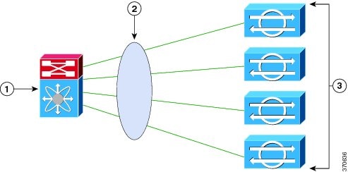
A port channel is created on the switch and the four physical interfaces that are connected to the IPS sensors are added to the port channel. The port channel supports load balancing to distribute the load among the members of the port channel. IPS sensors in an LACP port channel act as independent appliances. We recommend that you have the same configuration on all IPS sensors participating in the LACP port channel. You must configure each of the IPS interfaces in the LACP port channel in inline VLAN pair mode.
LACP is a point-to-point protocol and has two modes of operation—active and passive. Both are supported by the IPS. In active mode, Link Aggregation Control Protocol Data Units (LACPDUs) are periodically sent to actively probe for LACP support on the device on the other side. If the device on the other side responds to the LACP packets, an LACP connection is initiated. If LACP mode is configured as active, the connection is initiated as soon as the physical link is up.
In passive mode, the device does not actively send any LACP packets to probe the LACP device on the other end. It waits for the other side to probe and initiate an LACP connection. This can work only if the device on the other side supports LACP and is configured in active mode.
By default, LACP mode in IPS is disabled. Once LACP is enabled in the IPS, you must have it configured and operational in the switch, otherwise the LACP port will be either suspended or independent based on the switch side configuration.
Note We do not recommend that you enable LACP unless you are sure of the configuration on the other side.
Note We do not recommend that you configure UDLD with LACP.
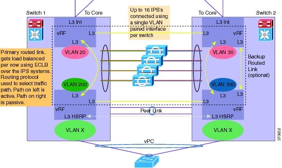
Figure 5-5 displays the recommended IPS LACP deployment in a data center environment:
Figure 5-5 Recommended IPS LACP Configuration
LACP Restrictions
Note We do not recommend that you configure UDLD with LACP.
Pay attention to the following when configuring LACP on the sensor:
- The IPS 4520 is the only platform that supports the dual configuration. You can add another 4520 module to an existing 4520 or you can order the 4520-XL with two modules already installed. Mixing 4510s and 4520s is not a valid configuration.
- Make sure that in your ECLB setup, you do not have multiple links within an EtherChannel going to the same IPS device, because this can lead to a load distribution imbalance.
- When a group of IPS devices participate in an LACP ether channel as one single device, the devices should all have the same system ID. The default system ID ensures this. However, if you have a requirement to have two different IPSes to have different system IDs in order to be able to distinguish them in the show LACP neighbor output, you can configure the LACP system priority, which influences the system ID.
- Make sure that the IPS interface that is part of the same LACP port channel is configured with the same VLAN pair.
- Make sure that bypass mode is off so that IPS can failover and fallback during failure conditions.
- Make sure the TCP session tracking mode is assigned to the virtual sensor, which is the default.
Understanding Failover/Fallback
The IPS has enhanced the support for seamless failover/fallback of TCP sessions from one sensor to another (nonconnection-based traffic, such as UDP and ICMP already had seamless support). The IPS determines that a gap in the state of the sessions being monitored may have been caused by failover/bypass/link flaps. It intelligently updates its state machine to restart the inspection of the sessions and ensures that the flows do not get dropped.
LACP Link States
The LACP link state represents whether the link can forward traffic or not and does not represent the actual link state of the physical port. LACP has two link states:
- Up—When the interface is up and the LACP state is either bundled or independent.
- Down (LACP suspended)—When the LACP configuration is mismatched on both ends, which means the LACP state is suspended and the switch does not allow traffic.
The following sequence of event leads to a link being up:
1.![]() At least two sensors are configured with the same channel ID.
At least two sensors are configured with the same channel ID.
2.![]() LACP is configured on both the switch and the sensor.
LACP is configured on both the switch and the sensor.
3.![]() The sensor participating in the same port channel must have the same system priority and channel ID.
The sensor participating in the same port channel must have the same system priority and channel ID.
4.![]() Interfaces participating in LACP must all have the same duplex and speed configuration.
Interfaces participating in LACP must all have the same duplex and speed configuration.
5.![]() The physical interface is up.
The physical interface is up.
The following sequence of events leads to a link going down.
Configuring LACP
Note Make sure that you have LACP configured on a Cisco Nexus 7K or Catalyst 6K switch before configuring LACP on the sensor.
Use these lacp commands in service interface submode to configure LACP on the sensor.
The following parameters apply:
- lacp-node-id number —Adds an LACP node identifier to the sensor. This ID uniquely identifies the node in the LACP group. The range is 1 to 16. The default is 1.
- lacp-system-priority number —Adds an LACP system priority to the sensor. Make sure the system priority is the same number across all of the nodes in the port channel. The range is 1 to 65535. The default is 32768.
- physical-interfaces interface_name —Creates a port channel on a physical interface:
–![]() subinterface-type inline-vlan-pair—Creates an inline VLAN pair.
subinterface-type inline-vlan-pair—Creates an inline VLAN pair.
–![]() lacp—Enters LACP configuration:
lacp—Enters LACP configuration:
channel-id number —Creates a port channel identifier. The range is 1 to 255. The default is 1.
lacp mode (active | passive | off) —Enables/disables LACP mode on a physical interface. The default is disabled.
LACP has two modes of operation: active and passive. Because LACP is a point-to-point protocol, in active mode, LACPDUs are periodically sent to actively probe for LACP support on the device other side. If the device on the other side responds to the LACP packets, an LACP connection is initiated. If LACP mode is configured active, this is done as soon as the physical link is up.
In passive mode, the device does not actively send any LACP packets to probe LACP devices on the other end. It waits for the other side to probe and initiate an LACP connection. This can work only if the device on the other side supports LACP and is configured in active mode.
Configuring LACP and Inline VLAN Pairs on the Sensor
To configure LACP and inline VLAN pairs on the sensor, follow these steps:
Step 2![]() Enter interface submode.
Enter interface submode.
Step 3![]() Assign the LACP node identification to the system. The default is 1.
Assign the LACP node identification to the system. The default is 1.
Step 4![]() Assign the system priority to the system. The default is 32768.
Assign the system priority to the system. The default is 32768.
Step 5![]() Configure inline VLAN pairs on the sensor.
Configure inline VLAN pairs on the sensor.
Step 6![]() Add the port channel to a physical interface and enable LACP. The default is disabled.
Add the port channel to a physical interface and enable LACP. The default is disabled.
Step 7![]() Verify the LACP settings.
Verify the LACP settings.
Step 8![]() Exit interface submode.
Exit interface submode.
Step 9![]() Press
Enter
to apply the changes or enter
no
to discard them.
Press
Enter
to apply the changes or enter
no
to discard them.
Displaying LACP
Use the show lacp ( neighbors | internals ) command in EXEC mode to display traffic statistics, system identifiers, and neighbor details.
Note The show interface and show interfaces brief also show the LACP status (susp, indep, and up).
The following parameters apply:
- neighbors —Displays system details of the neighbors.
- internals —Displays system details of the internals.
The output has the following fields:
–![]() A—The device is in active mode.
A—The device is in active mode.
–![]() F—The device is sending fast Link Aggregation Control Protocol Data Units (LACPDUs).
F—The device is sending fast Link Aggregation Control Protocol Data Units (LACPDUs).
–![]() S—The device is sending slow LACPDUs.
S—The device is sending slow LACPDUs.
–![]() P—The device is in passive mode.
P—The device is in passive mode.
–![]() Independent—LACP is configured at the local end and LACP is not configured on a partner/other end, for example, no LACP partner PDU is received.
Independent—LACP is configured at the local end and LACP is not configured on a partner/other end, for example, no LACP partner PDU is received.
–![]() Bundled—LACP is configured on both ends and able to create a bundle successfully; this means the configuration is valid and able to create a bundle.
Bundled—LACP is configured on both ends and able to create a bundle successfully; this means the configuration is valid and able to create a bundle.
–![]() Suspended—LACP is configured on both ends, but the received partner information is invalid’ this means there is an invalid configuration on the partner, such as half duplex on the link.
Suspended—LACP is configured on both ends, but the received partner information is invalid’ this means there is an invalid configuration on the partner, such as half duplex on the link.
- Port Priority—Displays the port priority in interfaces that have LACP enabled. The range is 1 to 65535 with the higher number signifying a lower priority. The default is 32768. The port priority is only displayed with the port is in active or passive mode.
- Admin Key—Displays the administrative key, which is a 16-bit number used by LACP to manage aggregation. For the IPS, the channel ID is used as the administrative key. All members of the port channel have the same administrative key assigned by the system as the channel ID.
- Oper Key—Displays the operational key, which is a 16-bit number assigned to an interface signifying that it can aggregate with all of the other interfaces that are assigned the same operational key. The operational key matches the administrative key.
- Port Number—Displays the port number, which is a 16-bit number used as the port aggregation priority. The IPS generates a unique port number by concatenating the LACP node identification number with the port number.
- Port State—Displays the state variables of the local/partner port encoded as individual bits within a single octet:
–![]() LACP_Activity—Encoded in bit 0. This flag indicates the activity control value with regard to this link. Active LACP is encoded as a 1; passive LACP is encoded as a 0.
LACP_Activity—Encoded in bit 0. This flag indicates the activity control value with regard to this link. Active LACP is encoded as a 1; passive LACP is encoded as a 0.
–![]() LACP_Timeout—Encoded in bit 1. This flag indicates the timeout control value with regard to this link. Short timeout is encoded as a 1; long timeout is encoded as a 0.
LACP_Timeout—Encoded in bit 1. This flag indicates the timeout control value with regard to this link. Short timeout is encoded as a 1; long timeout is encoded as a 0.
–![]() Aggregation—Encoded in bit 2. If TRUE (encoded as a 1), this flag indicates that the system considers this link to be suitable for aggregation; this means., it is a potential candidate for aggregation. If FALSE (encoded as a 0), the link is considered to be Individual; this means, this link can be operated only as an individual link.
Aggregation—Encoded in bit 2. If TRUE (encoded as a 1), this flag indicates that the system considers this link to be suitable for aggregation; this means., it is a potential candidate for aggregation. If FALSE (encoded as a 0), the link is considered to be Individual; this means, this link can be operated only as an individual link.
–![]() Synchronization—Encoded in bit 3. If TRUE (encoded as a 1), the system considers this link to be IN_SYNC; this means, it has been allocated to the correct Link Aggregation Group, the group has been associated with a compatible Aggregator, and the identity of the Link Aggregation Group is consistent with the system ID and operational key information transmitted. If FALSE (encoded as a 0), then this link is currently OUT_OF_SYNC; this means, it is not in the right aggregation.
Synchronization—Encoded in bit 3. If TRUE (encoded as a 1), the system considers this link to be IN_SYNC; this means, it has been allocated to the correct Link Aggregation Group, the group has been associated with a compatible Aggregator, and the identity of the Link Aggregation Group is consistent with the system ID and operational key information transmitted. If FALSE (encoded as a 0), then this link is currently OUT_OF_SYNC; this means, it is not in the right aggregation.
–![]() Collecting—Encoded in bit 4. TRUE (encoded as a 1) means collection of incoming frames on this link is definitely enabled; for example, collection is currently enabled and is not expected to be disabled in the absence of administrative changes or changes in received protocol information. Its value is otherwise FALSE (encoded as a 0).
Collecting—Encoded in bit 4. TRUE (encoded as a 1) means collection of incoming frames on this link is definitely enabled; for example, collection is currently enabled and is not expected to be disabled in the absence of administrative changes or changes in received protocol information. Its value is otherwise FALSE (encoded as a 0).
–![]() Distributing—Encoded in bit 5. FALSE (encoded as a 0) means distribution of outgoing frames on this link is definitely disabled; for example, distribution is currently disabled and is not expected to be enabled in the absence of administrative changes or changes in received protocol information. Its value is otherwise TRUE (encoded as a 1).
Distributing—Encoded in bit 5. FALSE (encoded as a 0) means distribution of outgoing frames on this link is definitely disabled; for example, distribution is currently disabled and is not expected to be enabled in the absence of administrative changes or changes in received protocol information. Its value is otherwise TRUE (encoded as a 1).
–![]() Defaulted—Encoded in bit 6. If TRUE (encoded as a 1), this flag indicates that the Actor’s receive machine is using defaulted operational partner information, administratively configured for the partner. If FALSE (encoded as a 0), the operational partner information in use has been received in a LACPDU.
Defaulted—Encoded in bit 6. If TRUE (encoded as a 1), this flag indicates that the Actor’s receive machine is using defaulted operational partner information, administratively configured for the partner. If FALSE (encoded as a 0), the operational partner information in use has been received in a LACPDU.
–![]() Expired—Encoded in bit 7. If TRUE (encoded as a 1), this flag indicates that the actor’s receive machine is in the EXPIRED state; if FALSE (encoded as a 0), this flag indicates that the actor's receive machine is not in the EXPIRED state.
Expired—Encoded in bit 7. If TRUE (encoded as a 1), this flag indicates that the actor’s receive machine is in the EXPIRED state; if FALSE (encoded as a 0), this flag indicates that the actor's receive machine is not in the EXPIRED state.
Note The received values of defaulted and expired state are not used by LACP; however, knowing their values can be useful when diagnosing protocol problems.
- System Priority—Displays the system-wide priority setting that is assigned to this interface. It is a 16-bit value with a range of 1 to 65535 and a default of 32768. In most cases, we recommend that you use the default.
- System Mac—Displays the hard-coded System MAC address, which is used across the IPS interfaces to establish the port channel across the IPS.
To display LACP information, follow these steps:
Step 2![]() Display the LACP information for neighbors.
Display the LACP information for neighbors.
Step 3![]() Show the LACP information for internals.
Show the LACP information for internals.
TxState: TRANSMIT_PDU(tt_expired)-> WAITED(ntt)-> TRANSMIT_PDU(tt_expired)-> WAITED(ntt)-> TRANSMIT_PDU(tt_expired)-> WAITED(ntt)-> TRANSMIT_PDU(tt_expired)-> WAITED(ntt)-> TRANSMIT_PDU(tt_expired)-> WAITED(ntt)
RxState: CURRENT(recv_lacpdu)-> CURRENT(recv_lacpdu)-> CURRENT(recv_lacpdu)-> CURRENT(recv_lacpdu)-> CURRENT(recv_lacpdu)-> CURRENT(recv_lacpdu)-> CURRENT(recv_lacpdu)-> CURRENT(recv_lacpdu)-> CURRENT(recv_lacpdu)-> CURRENT(recv_lacpdu)
PtxState: FAST_PERIODIC(pt_expired)-> PERIODIC_TX(short_timeout)-> FAST_PERIODIC(pt_expired)-> PERIODIC_TX(short_timeout)-> FAST_PERIODIC(pt_expired)-> PERIODIC_TX(short_timeout)-> FAST_PERIODIC(pt_expired)-> PERIODIC_TX(short_timeout)-> FAST_PERIODIC(pt_expired)-> PERIODIC_TX(short_timeout)
MuxState: COLLECTING_DISTRIBUTING(in_sync)-> COLLECTING_DISTRIBUTING(in_sync)-> COLLECTING_DISTRIBUTING(in_sync)-> COLLECTING_DISTRIBUTING(in_sync)-> COLLECTING_DISTRIBUTING(in_sync)-> COLLECTING_DISTRIBUTING(in_sync)-> COLLECTING_DISTRIBUTING(in_sync)-> COLLECTING_DISTRIBUTING(in_sync)-> COLLECTING_DISTRIBUTING(in_sync)-> COLLECTING_DISTRIBUTING(in_sync)
Configuring Inline Bypass Mode
This section describes inline bypass mode for sensors configured as inline interface and inline VLAN pairs, and contains the following topics:
Understanding Inline Bypass Mode
Note The ASA 5500-X IPS SSP and ASA 5585-X IPS SSP do not support bypass mode. The adaptive security appliance will either fail open, fail close, or fail over depending on the configuration of the adaptive security appliance and the type of activity being done on the IPS.
Caution There are security consequences when you put the sensor in bypass mode. When bypass mode is on, the traffic bypasses the sensor and is not inspected; therefore, the sensor cannot prevent malicious attacks.
Caution As with signature updates, when the sensor applies a global correlation update, it may trigger bypass. Whether or not bypass is triggered depends on the traffic load of the sensor and the size of the signature/global correlation update. If bypass mode is turned off, an inline sensor stops passing traffic while the update is being applied.
You can use inline bypass as a diagnostic tool and a failover protection mechanism. Normally, the sensor Analysis Engine performs packet analysis. When inline bypass is activated, the Analysis Engine is bypassed, allowing traffic to flow through the inline interfaces and inline VLAN pairs without inspection. Inline bypass ensures that packets continue to flow through the sensor when the sensor processes are temporarily stopped for upgrades or when the sensor monitoring processes fail. There are three modes: on, off, and automatic. By default, bypass mode is set to automatic.
The inline bypass functionality is implemented in software, so it only functions when the operating system is running. If the sensor is powered off or shut down, inline bypass does not work—traffic does not flow through the sensor.
For IPS 4510 and IPS 4520, when the SensorApp is not running or if bypass mode is on, the following occurs:
Configuring Inline Bypass Mode
Use the bypass-mode command in the service interface submode to configure bypass mode. The following commands apply:
- off —Turns off inline bypassing. Packet inspection is performed on inline data traffic. However, inline traffic is interrupted if the Analysis Engine is stopped.
- on —Turns on inline bypassing. No packet inspection is performed on the traffic. Inline traffic continues to flow even if the Analysis Engine is stopped.
- auto —Turns on automatic bypassing. The sensor automatically begins bypassing inline packet inspection if the Analysis Engine stops processing packets. This prevents data interruption on inline interfaces. This is the default.
To configure bypass mode, follow these steps:
Step 2![]() Enter interface submode.
Enter interface submode.
Step 5![]() Exit interface submode.
Exit interface submode.
Step 6![]() Press
Enter
to apply the changes or enter
no
to discard them.
Press
Enter
to apply the changes or enter
no
to discard them.
For more information on inline bypass mode, see Configuring Inline Bypass Mode.
Configuring Interface Notifications
You can configure the sensor to monitor the flow of packets across an interface and send notification if that flow changes (starts/stops) during a specified interval. You can configure the missed packet threshold within a specific notification interval and also configure the interface idle delay before a status event is reported.
Use the interface-notifications command in the service interface submode to configure traffic notifications.
The following parameters apply:
- default —Sets the value back to the system default setting.
- idle-interface-delay —Specifies the number of seconds an interface must be idle before sending a notification. The valid range is 5 to 3600. The default is 30 seconds.
- missed-percentage-threshold —Specifies the percentage of packets that must be missed during a specified interval before notification will be sent. The valid range is 0 to 100. The default is 0.
- notification-interval —Specifies the interval to check for missed packet percentage. The valid range is 5 to 3600. The default is 30 seconds
Configuring Interface Notifications
To configure the interface notification settings, follow these steps:
Step 2![]() Enter global configuration mode.
Enter global configuration mode.
Step 3![]() Enter interface submode.
Enter interface submode.
Step 4![]() Enter interface notifications submode.
Enter interface notifications submode.
Step 5![]() Specify the idle interface delay.
Specify the idle interface delay.
Step 6![]() Specify the missed percentage threshold.
Specify the missed percentage threshold.
Step 7![]() Specify the notification interval.
Specify the notification interval.
Step 9![]() Exit interface notifications submode.
Exit interface notifications submode.
Step 10![]() Press
Enter
to apply the changes or enter
no
to discard them.
Press
Enter
to apply the changes or enter
no
to discard them.
Configuring CDP Mode
Note The ASA 5500-X IPS SSP and ASA 5585-X IPS SSP do not support CDP mode.
You can configure the sensor to enable or disable the forwarding of CDP packets. This action applies globally to all interfaces.
Cisco Discovery Protocol is a media- and protocol-independent device-discovery protocol that runs on all Cisco-manufactured equipment, including routers, access servers, bridges, and switches. Using CDP, a device can advertise its existence to other devices and receive information about other devices on the same LAN or on the remote side of a WAN. CDP runs on all media that support SNAP, including LANs, Frame Relay, and ATM media.
User the cdp-mode command in service interface mode to have the sensor either forward or drop CDP packets.
The following parameter applies:
- cdp-mode { forward-cdp-packets | drop-cdp-packets }—Configures the sensor to either forward CDP packets or drop CDP packets. The default is drop-cdp-packets.
To configure CDP mode, follow these steps:
Step 2![]() Enter interface submode.
Enter interface submode.
Displaying Interface Statistics
Note The show interface command output for the IPS 4510 and IPS 4520 does not include the total undersize packets or total transmit FIFO overruns.
Note When the IPS 4510 and IPS 4520 are in bypass mode, VLAN statistics in the show interface and packet display/capture command output do not show any packets.
The jumbo packet count in the
show interface
command output from the lines
Total Jumbo Packets Received
and
Total Jumbo Packets Transmitted
for ASA IPS modules may be larger than expected due to some packets that were almost jumbo size on the wire being counted as jumbo size by the IPS. This miscount is a result of header bytes added to the packet by the ASA before the packet is transmitted to the IPS. For IPv4, 58 bytes of header data are added. For IPv6, 78 bytes of header data are added. The ASA removes the added IPS header before the packet leaves the ASA.
Use the show interfaces [ clear | brief ] command in EXEC mode to display statistics for all system interfaces. Use the show interfaces { FastEthernet | GigabitEthernet | Management | PortChannel } [ slot/port ] command to display statistics for specific interfaces.
- clear —(Optional) Clears the diagnostics.
- brief —(Optional) Displays a summary of the usability status information for each interface.
- FastEthernet —Displays statistics for FastEthernet interfaces.
- GigabitEthernet —Displays statistics for GigabitEthernet interfaces.
- Management —Displays statistics for Management interfaces.
Note Only platforms with external ports marked Management support this keyword.
- PortChannel —Displays statistics for PortChannel interfaces
- slot/port —Displays statistics for the specific slot/port of the interface.
Displaying Interface Statistics
To display interface statistics, follow these steps:
Step 2![]() Display statistics for all interfaces.
Display statistics for all interfaces.
Step 3![]() Show a brief summary of the interfaces. The * indicates that the interface is the command and control interface.
Show a brief summary of the interfaces. The * indicates that the interface is the command and control interface.
Step 4![]() Display the statistics for a specific interface.
Display the statistics for a specific interface.
For information on slot and port numbers and which platforms have a Management port, refer to Cisco Intrusion Prevention System Appliances and Modules Installation Guide for IPS 7.3 .
Displaying Interface Traffic History
Use the show interfaces-history [ traffic-by-hour | traffic-by-minute ] command in EXEC mode to display historical interfaces statistics for all system interfaces. The historical information for each interface is maintained for three days with 60 seconds granularity. Use the show interfaces-history {FastEthernet | GigabitEthernet | Management | PortChannel} [traffic-by-hour | traffic-by-minute ] command to display statistics for specific interfaces.
Note You must have health monitoring enabled to support the historic interface function.
Each record has the following details:
- Total packets received
- Total bytes received
- FIFO overruns
- Receive errors
- Received Mbps
- Missed packet percentage
- Average load
- Peak load
Note Historical data for each interface for the past 72 hours is also included in the show tech-support command.
- traffic-by-hour —Displays interface traffic history by the hour.
- traffic-by-minute —Displays interface traffic history by the minute.
- past —Displays historical interface traffic information.
- HH:MM —Specifies the amount of time to go back in the past to begin the traffic display. The range for HH is 0 to 72. The range for MM is 0 to 59. The minimum value is 00:01 and the maximum value is 72:00.
- FastEthernet —Displays statistics for FastEthernet interfaces.
- GigabitEthernet —Displays statistics for GigabitEthernet interfaces.
- Management —Displays statistics for Management interfaces.
Note Only platforms with external ports marked Management support this keyword.
Displaying Historical Interface Statistics
To display interface traffic history, follow these steps:
Step 2![]() Display the interface traffic history by the hour.
Display the interface traffic history by the hour.
Step 3![]() Display the interface traffic history by the minute.
Display the interface traffic history by the minute.
Step 4![]() Display the interface traffic history for a specific interface.
Display the interface traffic history for a specific interface.
For information on enabling health monitoring, see Configuring Health Status Information.
 Feedback