Feedback Feedback
|
Table Of Contents
Migration Guide for Converting Cisco PIX Configurations to Cisco ASA 5500 Series Configurations
Tool Assisted Configuration Conversion
Installing the PIX-to-ASA Migration Tool
Installing the OCC Tool (Optional)
Converting Cisco PIX Configurations to Cisco ASA 5500 Series Configurations
Retrieving the PIX Configuration
Converting the conduit and outbound Commands
Converting a Cisco PIX Configuration to a Cisco ASA 5500 Series Configuration
Viewing the Intermediate Configuration
Installing the Intermediate ASA Configuration
Configuring LAN-based Failover
Verifying the ASA Configuration
Manual Configuration Conversion
Retrieving the PIX Configuration
Multiple Context Mode Configuration Conversion
Obtaining Documentation, Obtaining Support, and Security Guidelines
Migration Guide for Converting Cisco PIX Configurations to Cisco ASA 5500 Series Configurations
July 2008Contents
•
Tool Assisted Configuration Conversion
•
•
Overview
Although the Cisco PIX 500 Series Security Appliances share a common software foundation with the Cisco ASA 5500 Series Adaptive Security Appliances, you cannot directly use a PIX configuration on an ASA security appliance. Differences between the platforms, such as physical interface names and the use of outbound and conduit commands, prevent PIX configurations from being used unmodified on ASA security appliances. However, if you are migrating from PIX security appliances to ASA security appliances in your network, you can convert the PIX configuration to an ASA configuration.
There are two ways to convert a PIX configuration to an ASA configuration:
•
•
Both methods have their own benefits and weaknesses. Both methods also allow you to perform the configuration conversion offline while your source PIX device remains in service on your network.
Manual Conversion Overview
With the manual conversion process, you use a text editor to go through you configuration line-by-line and convert PIX-specific commands to ASA commands.
Manual conversion of the PIX configuration to an ASA configuration gives you the most control over the conversion process. However, the process is time consuming and does not scale well if you must make more than one conversion.
Tool-Assisted Conversion Overview
We recommend that you use the tool-assisted conversion for converting PIX configurations to ASA configurations. This method uses two tools, the Outbound Conduit Conversion Tool and the Cisco PIX-to-ASA migration tool, to convert Cisco PIX Software version 6.3(x), 7.x, or 8.0 configurations to configurations that are usable on a Cisco ASA 5500 Series Adaptive Security Appliance.
The Outbound Conduit Conversion Tool (or optionally the Output Interpreter) converts the outbound and conduit commands to the equivalent access lists. The Cisco PIX-to-ASA migration tool converts the rest of the configuration to an intermediate configuration that can be processed by the adaptive security appliance.
The tool-assisted conversion method is faster and more scalable if you make multiple conversions. However, the output of the process in an intermediate configuration that contains both old syntax and new syntax. This method relies on installing the intermediate configuration on the target adaptive security appliance to complete the conversion. Until it is installed on the target device, you cannot view the final configuration.
Tool Assisted Configuration Conversion
This section contains the following topics:
•
Before You Begin
Before you begin the conversion process you must familiarize yourself with the important notes, verify the source and target platforms, and install the conversion utilities on your local computer.
This section contains the following topics:
•
•
•
•
Important Notes
•
•
•
•
•
•
•
Verifying the Source Platform
The source platform should meet the following requirements:
•
•
Verifying the Target Platform
To perform the migration, you must have an Cisco ASA 5500 Series Adaptive Security Appliance running Cisco ASA Software Version 7.2. Use the show version command or ASDM to determine the software version on the device.
Note
The following hardware platforms are supported:
•
•
•
•
•
•
Installing the PIX-to-ASA Migration Tool
The PIX-to-ASA migration tool is supported on Microsoft Windows 2000 or later, Red Hat Linux dated 2003 or later, or Mac OS X 1.4 or later. You must have Java Runtime Environment version 1.4.2 or later installed. We recommend that you use the latest version of either Java 1.4.2, Java 5 (1.5), or Java 6 (1.6). Java downloads may be obtained from http://www.java.com/en/download/index.jsp.
Note
Note
Installing on Microsoft Windows
To install the PIX-to-ASA migration tool on Windows, perform the following steps:
Step 1
PIXtoASAsetup.exefile from the Cisco Software Center at the following URL:http://www.cisco.com/cisco/software/navigator.html?a=a
Step 2
The PIX-to-ASA migration tool installation wizard opens.
Step 3
The Destination Folder screen appears. (Optional) To change the install location, perform the following steps:
a.
b.
c.
Step 4
The Setup Type screen appears. Select the setup type you prefer, and click Next.
You can choose between a complete installation and a custom installation:
•
•
Step 5
Note
The Ready to Install the Program screen appears.
Step 6
Step 7
Tip
The Install Wizard adds a Cisco PIX-to-ASA migration tool folder to your Start menu. The folder contains shortcuts to the Migration Guide for Converting Cisco PIX Configurations to Cisco ASA 5500 Series Configurations document, the PIX-to-ASA migration tool, and the PIX-to-ASA migration tool uninstaller.
Installing on MAC OS X
To install the PIX-to-ASA migration tool on MAC OS X, perform the following steps:
Step 1
PIX_to_ASA.dmgdisk image file from the Cisco Software Center.Step 2
A PIX to ASA folder opens on your desktop. If the folder does not open, double-click the PIX to ASA virtual disk icon that is on the desktop.
Step 3
Although you do not need to keep a copy of the extracted files on your system, keeping a copy of the files may be useful if you plan to use the scripting tools.
Step 4
Note
The archive contains PIXtoASA.app (a Macintosh GUI application), an executable JAR for scripts, a Bourne shell script, and the user documentation in PDF format.
Installing on Linux
To install the PIX-to-ASA migration tool on Red Hat Linux, perform the following steps:
Step 1
PIXtoASA.zipfile from the Cisco Software Center.Step 2
The file contains a PDF file of the user documentation, a Bourne shell script that can be used to launch the application, and an executable JAR file.
Installing the OCC Tool (Optional)
The OCC Tool is supported on Microsoft Windows and Sun Solaris only. The OCC tool runs on Windows 95, Windows 98, Windows 2000, Windows XP, and Solaris 2.8 (SunOS 5.8).
If you must convert the outbound and conduit commands on a Linux or Macintosh workstation, you must use the Output Interpreter. See Converting the conduit and outbound Commands.
Installing the OCC Tool on Microsoft Windows
To install the OCC tool on Microsoft Windows, perform the following steps:
Step 1
occ-121.zipfile from the Cisco Software Center.Step 2
The archive contains the occ-121.exe Windows binary file.
Installing the OCC Tool on SUN Solaris
To install the OCC tool on SUN Solaris, perform the following steps:
Step 1
occ-121.gzfile from the Cisco Software Center.Step 2
The archive contains the occ-121 Solaris binary file.
Converting Cisco PIX Configurations to Cisco ASA 5500 Series Configurations
Table 1 provides a summary of the steps necessary to convert your PIX configuration to an ASA configuration.
Table 1 Conversion Process Summary
Step 1
Retrieve the PIX configuration from the device.
Step 2
Convert the PIX conduit and outbound commands.
Step 3
Convert the PIX configuration to an ASA configuration.
Converting a Cisco PIX Configuration to a Cisco ASA 5500 Series Configuration
Step 4
View the converted, intermediate configuration.
Step 5
Complete the conversion process by installing the converted configuration on an ASA 5500 Series Adaptive Security Appliance running 7.0(x), 7.2(x), or 8.x software.
Step 6
(Optional) Configure LAN-based failover (if converting from a serial cable failover configuration).
Step 7
Verify the final, converted configuration.
Step 8
Deploy your new device.
Retrieving the PIX Configuration
Retrieve the PIX configuration from the source device, and store it on your local file system. You can retrieve a PIX configuration in the following ways:
•
•
•
Note
Do not use the show config, show running-config, or show running-config all commands to retrieve the configuration. These commands obscure passwords with asterisks (*) and may not display information that PDM or Cisco ASDM uses to maintain network object and group names. Using those commands may also display the configuration with unwanted line wrapping or the --- MORE --- prompt embedded in the output, both of which can introduce errors in the converted configuration.
Converting the conduit and outbound Commands
The recommended method for converting conduit and outbound commands is to use the OCC tool. However, the OCC tool is only supported on Windows and Solaris. To convert conduit and outbound commands on Linux or Macintosh, you must use the online Output Interpreter tool. See https://www.cisco.com/cgi-bin/Support/OutputInterpreter/home.pl.
Note
A conduit permits connections from one network interface to access hosts on another. The OCC tool checks for overlaps between the global address of the conduit and each of the following:
•
•
•
•
Note
Note
If no overlaps apply, the OCC tool does not create an ACL entry for the conduit on that particular interface.
An outbound list is based on the source IP address, the destination IP address, and the destination port or protocol, as specified by the access rules. Outbound lists control Internet use by specifying the following:
•
•
•
The PIX security appliance uses an algorithm to determine which outbound command to apply to a given incoming packet. Packets are denied by either the outgoing_src list or the outgoing_dst list. The OCC tool considers an outbound command with a narrower address mask to be a better match, regardless of the service. If the address masks are equal, a more specific service is a better match.
To convert conduit and outbound commands using the OCC tool, perform the following steps:
Step 1
Step 2
Step 3
occ old_config new_configThe old_config argument is the configuration file retrieved from the PIX security appliance. The new_config argument is the name you want the tool to use when it generates the changed configuration file.
The tool creates a new configuration file with the outbound and conduit commands converted to the appropriate ACL configurations. Use this new configuration file for the rest of the conversion process.
Converting a Cisco PIX Configuration to a Cisco ASA 5500 Series Configuration
The Cisco PIX to ASA migration tool supports both GUI and CLI-based operation, giving administrators flexibility in how they use this tool. The graphical interface guides administrators through the entire process, from selecting input/output files, to selecting the migration target platform, to mapping network interfaces, and then to generating the newly migrated configuration. The CLI enables the same capabilities, but it gives administrators the ability to create scripts to easily perform bulk migrations. This tool helps to expedite the migration process and to prevent administrators from making common mistakes when performing manual migrations.
The following methods can be used to convert the configuration from PIX to ASA:
•
•
Using the GUI
We recommend that you use the GUI for converting the PIX configuration to ASA. The GUI provides all of the capabilities of the CLI. Unlike the command line tool, all GUI interface configuration input and output occurs through files, rather than process standard input, output, and error output.
To migrate a PIX security appliance to an ASA security appliance using the GUI, perform the following steps:
Step 1
•
•
•
java -jar PIXtoASA.jar -gui
Note
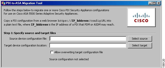
Step 2
Figure 1 Specify Source and Target Files
a.
Note
b.
Note
If the results of the source configuration file scan contain warnings for unsupported commands, you are not permitted to proceed unless you check the Allow unsupported apply, conduit, and outbound commands button.
Caution
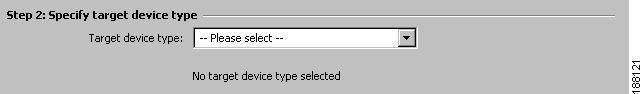
Step 3
Figure 2 Specify Target Device Type
Target device types are specified because of the differences in the number of available interfaces.
You may choose from the following list of target device types:
•
•
•
•
•
•
•
•
•
•
•
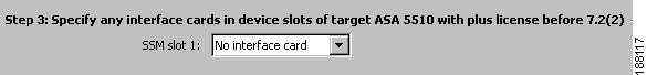
Step 4
Figure 3 Specify Interface Cards in Device Slots
For each available slot of the device type, the potential interface card names are listed, if any. Cards without external interfaces are not listed.
Note
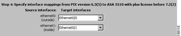
Step 5
Figure 4 Specify Interface Mappings
Each interface found in the source configuration file is shown with a drop-down list of the target device type interfaces and its interface cards in slots. An attempt is made to match the fastest source interfaces with the fastest target interfaces in the expected order by listing the potentially fastest interfaces with the lowest port number first.
Except for the Cisco ASA 5580, which may be specified only with Management interfaces, Management interfaces are not initially selected because they are not intended for ordinary use for through-the-box traffic. If the target device does not have enough interfaces to be matched uniquely with source interfaces, any remaining source interfaces are mapped to the last acceptable target interface. In this case, you must explicitly specify which source interfaces will map to either a Management interface or to no target interface. To avoid possible misconfiguration, an alert appears for duplicate mappings.
Caution
Step 6
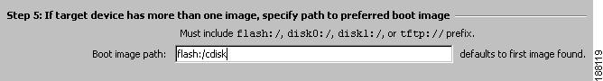
Figure 5 Specify Path to Preferred Boot Image
Even through the configuration file may not specify a boot image, the ASA ROM configuration may specify a boot image from a previous write memory operation.
If the ASA configuration specifies no boot images, the first image found is used while reloading.
Step 7
Note
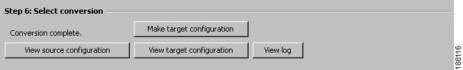
Figure 6 Initiate Conversion
During the conversion a status bar shows the percentage of the configuration that has completed. When conversion has finished, a message appears to inform you that the conversion has completed or has failed with an exception. If the conversion fails, the exception information is appended to the log.
You can view the source configuration, target configuration, and log files if they exist. When the viewing files are opened or reopened, the contents are refreshed from the corresponding file.
If you want to convert more than one source configuration file during a session, return to the step that specifies the source file and input a new file.
Populating the GUI Using CLI Options
When launching the GUI from the CLI, you may use the following optional parameters to prepopulate the GUI:
•
[-gui]
•
[-f input_file | --input-file=input_file]
•
[-o output_file | --output-file=output_file]
•
[-l log_file | --log-file=log_file]
•
[-a log_file | --append-log-file=log_file]
•
[-overwrite]
•
[-console]
Using the CLI Syntax
To migrate a PIX security appliance to an ASA security appliance using the command line interface, use the following command at the command prompt:
java -jar PIXtoASA.jar [options]
Note
Example
The following example shows how to run the Java, non-GUI mode, of the tool, specifying the target platform as an ASA-5540 and redirecting the source PIX configuration into the tool:
java -jar PIXtoASA.jar -t asa-5540 < PIX501config.txtINFO: PIX to ASA conversion tool $Revision: 1.9 $INFO: PIX Version 6.3(4) Removed from configINFO: fixup protocol sip udp 5060 Removed from configWARNING: The configuration is NOT supported - floodguard enableWARNING: Your password is set to all STARS(*) Please Correct before deploying to the new device! 'vpdn username cisco password ********* 'INFO: Cryptochecksum:e136533e23231c5bbbbf4088cee75a5a Removed from configINFO: : end Removed from configINFO: The destination platform is: asa-5540INFO: Interface Mapping:'ethernet0 '-> 'GigabitEthernet0/0''ethernet1 '-> 'GigabitEthernet0/1'Additional Files Provided
Two additional files are provided for your convenience. Each contains the java -jar PIXtoASA.jar command and can be used to invoke scripts.
•
•
These files must be in the same directory as the PIXtoASA.jar file in order to call the file correctly.
Bundled Platforms
When using bundled platforms with fixed configurations to map interfaces, the source platform interface is automatically mapped to the next available destination platform interface on a first-come first-served basis. The target platform is specified using the keyword -t in the CLI syntax.
Table 2 lists the ASA platform interface mappings.
Explicit Interface Mapping
When using explicit interface mapping to map interfaces, you must specify a complete interface mapping scheme, including the full names of all interfaces involved. Explicit interface mapping is specified using the keyword -m in the CLI syntax.
In the following example, ethernet0 is mapped to gigabitethernet0/0, and ethernet1 is mapped to gigabitethernet0/1:
java -jar PIXtoASA.jar -t asa-5540 -m ethernet0@gigabitethernet0/0 -m
ethernet2@gigabitethernet0/1
Note
java -jar PIXtoASA.jar -t asa-5540 -m ethernet0@gigabitethernet0/0 -m
ethernet2@gigabitethernet0/1
Viewing the Intermediate Configuration
You can view the intermediate configuration in two ways:
•
•
Note
Warnings are generated as inline comments in the converted configuration. You receive warnings if the following apply:
•
•
•
Installing the Intermediate ASA Configuration
The intermediate configuration generated by the tool must be loaded into the startup configuration on an ASA device for final conversion by the platform. (If loaded into the running configuration, some intermediate CLI might not be correctly converted.) It can also be imported into Cisco Security Manager (CSM) or the Cisco Adaptive Security Device Manager (ASDM).
See the Command Line Configuration Guide for your target version of ASA software for more information about configuring your device for CLI or ASDM access: http://www.cisco.com/en/US/products/ps6120/products_installation_and_configuration_guides_list.html
To install the intermediate ASA configuration and complete the conversion process, perform the following steps:
Step 1
•
•
Step 2
•
•
copy disk0:/startupconfigfilename startup-config
Note
Caution
Step 3
•
•
Configuring LAN-based Failover
If you converted from a PIX security appliance that used serial cable failover, you will need to add LAN-based failover commands to the configuration.
To enable LAN-based failover, perform the following steps:
Step 1
hostname(config)# failover lan interface if_name phy_ifThe if_name argument assigns a name to the interface specified by the phy_if argument. The phy_if argument can be the physical port name, such as Ethernet0/1, or a previously created subinterface, such as Ethernet0/2.3. On the Cisco ASA 5505 Adaptive Security Appliance, the phy_if specifies a VLAN.
Step 2
hostname(config)# failover interface ip if_name ip_addr mask standby ip_addrThe standby IP address must be in the same subnet as the active IP address. You do not need to identify the standby address subnet mask.
The failover link IP address and MAC address do not change at failover. The active IP address for the failover link always stays with the primary unit, while the standby IP address stays with the secondary unit.
Step 3
hostname(config)# interface phy_ifhostname(config-if)# no shutdownSee the Command Line Configuration Guide for your target version of Cisco ASA Software for more information about configuring LAN-based failover: http://www.cisco.com/en/US/products/ps6120/products_installation_and_configuration_guides_list.html
Verifying the ASA Configuration
There are several ways that you can confirm the accuracy of the new ASA configuration. Use the command show startup-config errors to view any errors the ASA detected as it booted. The command show running-config tech is also useful for confirming your ASA configuration.
You may also view the new configuration in ASDM. In ASDM, you should verify the access lists, configured hardware ports, interfaces, and inspections. From the CLI, you should use the commands show run interface, show access lists, and check the inspections to verify they have been configured correctly.
Finally, you should test the configuration for the desired behavior. You can use the packet-tracer command, or you can use the Packet Tracer utility in the ASDM Tools Menu.
Deploying the New Device
Once you have verified the new configuration, put the new device into production. The new device should have the same IP addresses as the PIX security appliance being replaced. You should remove the PIX security appliance from the network before bring the new device online to avoid address conflicts.
Manual Configuration Conversion
Table 3 provides a summary of the steps needed to convert your PIX configuration to an ASA configuration.
Retrieving the PIX Configuration
Retrieve the PIX configuration from the source device and store it on your local file system. You can retrieve a PIX configuration in the following ways:
•
•
•
Note
Do not use the show config, show running-config, or show running-config all commands to retrieve the configuration. These commands obscure passwords with asterisks (*) and may not display information that PDM or ASDM uses to maintain network object and group names. Using those commands may also display the configuration with unwanted line wrapping or the --- MORE --- prompt embedded in the output, both of which can introduce errors in the converted configuration.
Mapping Commands Manually
Performing a manual conversion is the most time-consuming method, yet it allows for the most control over the conversion. The manual conversion includes following sections:
•
Interface Mapping
One of the major functions of the conversion is to map the interface names of the PIX security appliance, which are ethernet0 and gb-ethernet0, to the ASA security appliance naming that is based on chassis slot number and interface number such as: Ethernet0/0, GigabitEthernet0/0, GigabitEtherent1/0, for example.
Remapping of interfaces can be performed manually, but the task can be time consuming and prone to error. The Cisco PIX to ASA migration tool automates this process.
There are two ways of mapping interfaces using the PIX to ASA migration tool:
•
•
Note
By default, switch interface Ethernet0/0 is mapped as an access port in VLAN2. The rest of the interfaces on the switch are access ports in VLAN1. If the source platform has more interfaces than that, it is necessary to manually change the switch configuration to reflect the proper VLAN-to-switch port mapping.
The ASA platform, and all PIX 7.x and higher, define interface characteristics via sub commands under the interface as known from IOS. The source platform interface characteristics are automatically represented as the proper interface sub commands.
In pre 7.0 software interfaces names, logical names, ip addresses, network masks failover ip addresses are all configured as separate commands scattered throughout the configuration. In 7.x and forward all this information is configured in the IOS way of interface and sub commands under the interface.
Table 4 lists the sample converted interface constructs from PIX/ASA version 6.3 to PIX/ASA version 7.2(2).
FIXUP Conversion
In ASA 7.x, application inspection was introduced as inspection maps and the inspect syntax; this is defined in software versions prior to 7.0 as fixups.
FIXUPs for standard ports are converted into the global inspection policy, as shown in Table 5.
FIXUPs on other ports are retained in their FIXUP format and left to be converted by the platform or CSM. Those platforms will create separate class maps and inspection-maps for their corresponding FIXUP.Table 5 lists sample FIXUP conversion commands from PIX/ASA version 6.3 to PIX/ASA version 7.2(2).
LAN-Based Failover
PIX failover configuration is converted to ASA failover syntax. Failover IP address section (standby IP addresses) are also converted.
Note
Example
The following example is a PIX LAN Failover Configuration Conversion.
PIX 6.3(5) configuration (before conversion):
interface gb-ethernet0 1000autointerface gb-ethernet1 1000autointerface gb-ethernet2 1000autointerface gb-ethernet2 vlan50 logicalinterface gb-ethernet2 vlan55 logicalinterface ethernet0 100fullinterface ethernet1 100fullnameif gb-ethernet0 outside security0nameif gb-ethernet1 inside security100nameif gb-ethernet2 dmz security8nameif ethernet0 eng security4nameif ethernet1 mkt security4nameif vlan50 vlan50 security10nameif vlan55 vlan55 security12ip address outside 5.5.5.45 255.255.255.0ip address inside 14.36.8.48 255.255.0.0ip address dmz 1.1.1.6 255.255.255.0ip address mkt 2.2.2.2 255.255.255.0ip address vlan50 50.1.1.1 255.0.0.0failoverfailover timeout 0:00:00failover poll 15failover ip address outside 5.5.5.68failover ip address inside 14.36.199.34failover ip address mkt 2.2.2.4failover ip address vlan50 50.1.1.2failover lan unit primaryfailover lan interface mktfailover link vlan55failover lan enableConverted ASA configuration:
interface GigabitEthernet0/0ip address 5.5.5.45 255.255.255.0 standby 5.5.5.68nameif outsidesecurity-level 0: Original Interface id gb-ethernet1interface GigabitEthernet0/1ip address 14.36.8.48 255.255.0.0 standby 14.36.199.34nameif insidesecurity-level 100: Original Interface id gb-ethernet2interface GigabitEthernet0/2ip address 1.1.1.6 255.255.255.0nameif dmzsecurity-level 8: Original Interface id gb-ethernet2_50interface GigabitEthernet0/2.50vlan 50ip address 50.1.1.1 255.0.0.0 standby 50.1.1.2nameif vlan50security-level 10: Original Interface id gb-ethernet2_55interface GigabitEthernet0/2.55vlan 55no ip addressno shutdown: Original Interface id ethernet0interface GigabitEthernet0/3no ip addressno shutdownnameif eng: Original Interface id ethernet1: Failoverinterface GigabitEthernet1/0security-level 4failoverfailover timeout 0:00:00:::: your failover poll timer syntax has been corrected from'failover poll 15' to 'failover polltime 15'failover polltime 15failover lan unit primary::::failover lan interface mkt -> failover lan interface mkt GigabitEthernet1/0failover lan interface mkt GigabitEthernet1/0failover interface ip mkt 2.2.2.2 255.255.255.0 standby 2.2.2.4::::failover link vlan55 -> failover link vlan55 GigabitEthernet0/2.55failover link vlan55 GigabitEthernet0/2.55failover interface ip vlan55 0.0.0.0 0.0.0.0 standby 0.0.0.0:::: Not supported - failover lan enableDynamic Interface Addressing
Interface IP addressing is supported on the PIX platform as static address assignment and as dynamic addressing for DHCP and PPPOE.
Multiple Context Mode Configuration Conversion
When converting a multiple context mode configuration from PIX to ASA, you only need to convert the system context configuration. You use the allocate-interface command in the system context to map the ASA physical interface names to the corresponding PIX interface names, which are then used by the individual security contexts.
To convert the system context, perform the following steps:
Step 1
Step 2
hostname(config-ctx)# allocate-interface physical_interface [mapped_interface_name]For example, the command allocate-interface ethernet0 could become allocate-interface GigabitEthernet0/0 ethernet0
Note
Deploying the New Device
Once you have verified the new configuration, put the new device into production. The new device will have the same IP addresses as the PIX security appliance being replaced. You should remove the PIX security appliance from the network before bring the new device online to avoid address conflicts.
Related Documentation
For additional information on the adaptive security appliance, go to:
http://www.cisco.com/en/US/products/ps6120/tsd_products_support_series_home.html
Obtaining Documentation, Obtaining Support, and Security Guidelines
For information on obtaining documentation, obtaining support, providing documentation feedback, security guidelines, and also recommended aliases and general Cisco documents, see the monthly What's New in Cisco Product Documentation, which also lists all new and revised Cisco technical documentation, at:
http://www.cisco.com/en/US/docs/general/whatsnew/whatsnew.html
This document is to be used in conjunction with the documents listed in the "Related Documentation" section.
CCVP, the Cisco logo, and the Cisco Square Bridge logo are trademarks of Cisco Systems, Inc.; Changing the Way We Work, Live, Play, and Learn is a service mark of Cisco Systems, Inc.; and Access Registrar, Aironet, BPX, Catalyst, CCDA, CCDP, CCIE, CCIP, CCNA, CCNP, CCSP, Cisco, the Cisco Certified Internetwork Expert logo, Cisco IOS, Cisco Press, Cisco Systems, Cisco Systems Capital, the Cisco Systems logo, Cisco Unity, Enterprise/Solver, EtherChannel, EtherFast, EtherSwitch, Fast Step, Follow Me Browsing, FormShare, GigaDrive, HomeLink, Internet Quotient, IOS, iPhone, IP/TV, iQ Expertise, the iQ logo, iQ Net Readiness Scorecard, iQuick Study, LightStream, Linksys, MeetingPlace, MGX, Networking Academy, Network Registrar, Packet, PIX, ProConnect, ScriptShare, SMARTnet, StackWise, The Fastest Way to Increase Your Internet Quotient, and TransPath are registered trademarks of Cisco Systems, Inc. and/or its affiliates in the United States and certain other countries.
All other trademarks mentioned in this document or Website are the property of their respective owners. The use of the word partner does not imply a partnership relationship between Cisco and any other company. (0705R)
© 2008 Cisco Systems, Inc.
All rights reserved.