Table Of Contents
Implementing Multipoint Layer 2 Bridging Services (VPLS) on Cisco ASR 9000 Series Routers
Contents
Prerequisites for Implementing Virtual Private LAN Services
Information About Implementing Virtual Private LAN Services
Virtual Private LAN Services Overview
VPLS Architecture
VPLS for an MPLS-based Provider Core
Signaling
Multiple Spanning Tree Protocol
Multiple Spanning Tree Protocol Overview
Bridge Protocol Data Units
MAC Address-related Parameters
MAC Address Flooding
MAC Address-based Forwarding
MAC Address Source-based Learning
MAC Address Aging
MAC Address Limit
MAC Address Withdrawal
LSP Ping over VPWS and VPLS
Split Horizon Groups
Layer 2 Security
Port Security
Dynamic Host Configuration Protocol Snooping
How to Implement Virtual Private LAN Services
Configuring a Bridge Domain
Creating a Bridge Domain
Configuring a Pseudowire
Associating Members with a Bridge Domain
Configuring Bridge Domain Parameters
Disabling a Bridge Domain
Verifying the Multiple Spanning Tree Protocol
Configuring Layer 2 Security
Enabling Layer 2 Security
Attaching a Dynamic Host Configuration Protocol Profile
Configuring a Layer 2 Virtual Forwarding Instance
Adding the Virtual Forwarding Instance Under the Bridge Domain
Associating Pseudowires with the Virtual Forwarding Instance
Associating a Virtual Forwarding Instance to a Bridge Domain
Attaching Pseudowire Classes to Pseudowires
Configuring Any Transport over Multiprotocol Pseudowires By Using Static Labels
Disabling a Virtual Forwarding Instance
Configuring the MAC Address-related Parameters
Configuring the MAC Address Source-based Learning
Enabling the MAC Address Withdrawal
Configuring the MAC Address Limit
Configuring the MAC Address Aging
Configuring an AC to the AC Split Horizon Group
Configuration Examples for Virtual Private LAN Services
Virtual Private LAN Services Configuration for Provider Edge-to-Provider Edge: Example
Virtual Private LAN Services Configuration for Provider Edge-to-Customer Edge: Example
Displaying MAC Address Withdrawal Fields: Example
Adding ACs to a Split Horizon Group: Example
Additional References
Related Documents
Standards
MIBs
RFCs
Technical Assistance
Implementing Multipoint Layer 2 Bridging Services (VPLS) on Cisco ASR 9000 Series Routers
This module provides the conceptual and configuration information for Multipoint Layer 2 Bridging Services, also called Virtual Private LAN Services (VPLS) on Cisco ASR 9000 Series Aggregation Services Routers. VPLS supports Layer 2 VPN technology and provides transparent multipoint Layer 2 connectivity for customers.
This approach enables service providers to host a multitude of new services such as broadcast TV and Layer 2 VPNs.
For MPLS Layer 2 virtual private networks (VPNs), see the Implementing MPLS Layer 2 VPNs on Cisco ASR 9000 Series Routers module in this document.
Note  For more information about MPLS Layer 2 VPN on Cisco ASR 9000 Series Routers and for descriptions of the commands listed in this module, see the "Related Documents" section. To locate documentation for other commands that might appear while executing a configuration task, search online in the Cisco IOS XR software master command index.
Feature History for Implementing Virtual Private LAN Services on Cisco ASR 9000 Series Routers
Release
|
Modification
|
Release 3.7.2
|
This feature was introduced on Cisco ASR 9000 Series Routers.
|
Contents
•Prerequisites for Implementing Virtual Private LAN Services
•Information About Implementing Virtual Private LAN Services
•How to Implement Virtual Private LAN Services
•Configuration Examples for Virtual Private LAN Services
•Additional References
Prerequisites for Implementing Virtual Private LAN Services
Before you configure VPLS, ensure that the network is configured as follows:
•Configure IP routing in the core so that the provider edge (PE) routers can reach each other through IP.
•Configure MPLS and Label Distribution Protocol (LDP) in the core so that a label switched path (LSP) exists between the PE routers.
•Configure a loopback interface to originate and terminate Layer 2 traffic. Make sure that the PE routers can access the other router's loopback interface.
Note The loopback interface is not needed in all cases. For example, tunnel selection does not need a loopback interface when VPLS is directly mapped to a TE tunnel.
You must be in a user group associated with a task group that includes the proper task IDs. The command reference guides include the task IDs required for each command. If you suspect user group assignment is preventing you from using a command, contact your AAA administrator for assistance.
Information About Implementing Virtual Private LAN Services
To implement Virtual Private LAN Services (VPLS), you should understand the following concepts:
•Virtual Private LAN Services Overview
•VPLS for an MPLS-based Provider Core
•Signaling
•Multiple Spanning Tree Protocol
•MAC Address-related Parameters
•LSP Ping over VPWS and VPLS
•Split Horizon Groups
•Layer 2 Security
Virtual Private LAN Services Overview
Virtual Private LAN Service (VPLS) enables geographically separated local-area network (LAN) segments to be interconnected as a single bridged domain over an MPLS network. The full functions of the traditional LAN such as MAC address learning, aging, and switching are emulated across all the remotely connected LAN segments that are part of a single bridged domain.
Some of the components present in a VPLS network are described in the following sections.
Bridge Domain
The native bridge domain refers to a Layer 2 broadcast domain consisting of a set of physical or virtual ports (including VFI). Data frames are switched within a bridge domain based on the destination MAC address. Multicast, broadcast, and unknown destination unicast frames are flooded within the bridge domain. In addition, the source MAC address learning is performed on all incoming frames on a bridge domain. A learned address is aged out. Incoming frames are mapped to a bridge domain, based on either the ingress port or a combination of both an ingress port and a MAC header field.
By default, split horizon is enabled on a bridge domain. In other words, any packets that are coming on either the attachment circuits or pseudowires are not returned on the same attachment circuits or pseudowires. In addition, the packets that are received on one pseudowire are not replicated on other pseudowires in the same VFI.
Pseudowires
A pseudowire is a point-to-point connection between pairs of PE routers. Its primary function is to emulate services like Ethernet over an underlying core MPLS network through encapsulation into a common MPLS format. By encapsulating services into a common MPLS format, a pseudowire allows carriers to converge their services to an MPLS network.
Virtual Forwarding Instance
VPLS is based on the characteristic of virtual forwarding instance (VFI). A VFI is a virtual bridge port that is capable of performing native bridging functions, such as forwarding, based on the destination MAC address, source MAC address learning and aging, and so forth.
A VFI is created on the PE router for each VPLS instance. The PE routers make packet-forwarding decisions by looking up the VFI of a particular VPLS instance. The VFI acts like a virtual bridge for a given VPLS instance. More than one attachment circuit belonging to a given VPLS are connected to the VFI. The PE router establishes emulated VCs to all the other PE routers in that VPLS instance and attaches these emulated VCs to the VFI. Packet forwarding decisions are based on the data structures maintained in the VFI.
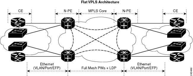
VPLS Architecture
The basic or flat VPLS architecture allows for the end-to-end connection between the provider edge (PE) routers to provide multipoint ethernet services. Figure 20 shows a flat VPLS architecture illustrating the interconnection between the network provider edge (N-PE) nodes over an IP/MPLS network.
Figure 20 Basic VPLS Architecture
The VPLS network requires the creation of a bridge domain (Layer 2 broadcast domain) on each of the PE routers. The VPLS provider edge device holds all the VPLS forwarding MAC tables and bridge domain information. In addition, it is responsible for all flooding broadcast frames and multicast replications.
The PEs in the VPLS architecture are connected with a full mesh of Pseudowires (PWs). A Virtual Forwarding Instance (VFI) is used to interconnect the mesh of pseudowires. A bridge domain is connected to a VFI to create a Virtual Switching Instance (VSI), that provides Ethernet multipoint bridging over a PW mesh. VPLS network links the VSIs using the MPLS pseudowires to create an emulated Ethernet Switch.
With VPLS, all customer equipment (CE) devices participating in a single VPLS instance appear to be on the same LAN and, therefore, can communicate directly with one another in a multipoint topology, without requiring a full mesh of point-to-point circuits at the CE device. A service provider can offer VPLS service to multiple customers over the MPLS network by defining different bridged domains for different customers. Packets from one bridged domain are never carried over or delivered to another bridged domain, thus ensuring the privacy of the LAN service.
VPLS transports Ethernet IEEE 802.3, VLAN IEEE 802.1q, and VLAN-in-VLAN (q-in-q) traffic across multiple sites that belong to the same Layer 2 broadcast domain. VPLS offers simple VLAN services that include flooding broadcast, multicast, and unknown unicast frames that are received on a bridge. The VPLS solution requires a full mesh of pseudowires that are established among PE routers. The VPLS implementation is based on Label Distribution Protocol (LDP)-based pseudowire signaling.
VPLS for an MPLS-based Provider Core
VPLS is a multipoint Layer 2 VPN technology that connects two or more customer devices using bridging techniques. A bridge domain, which is the building block for multipoint bridging, is present on each of the PE routers. The access connections to the bridge domain on a PE router are called attachment circuits. The attachment circuits can be a set of physical ports, virtual ports, or both that are connected to the bridge at each PE device in the network.
After provisioning attachment circuits, neighbor relationships across the MPLS network for this specific instance are established through a set of manual commands identifying the end PEs. When the neighbor association is complete, a full mesh of pseudowires is established among the network-facing provider edge devices, which is a gateway between the MPLS core and the customer domain.
The MPLS/IP provider core simulates a virtual bridge that connects the multiple attachment circuits on each of the PE devices together to form a single broadcast domain. This also requires all of the PE routers that are participating in a VPLS instance to form emulated virtual circuits (VCs) among them.
Now, the service provider network starts switching the packets within the bridged domain specific to the customer by looking at destination MAC addresses. All traffic with unknown, broadcast, and multicast destination MAC addresses is flooded to all the connected customer edge devices, which connect to the service provider network. The network-facing provider edge devices learn the source MAC addresses as the packets are flooded. The traffic is unicasted to the customer edge device for all the learned MAC addresses.
Signaling
An important aspect of VPN technologies, including VPLS, is the ability of network devices to automatically signal to other devices about an association with a particular VPN, often referred to as signaling mechanisms. For VPLS, this includes discovery of other peers and MAC address withdrawal.
The implementation of VPLS in a network requires the establishment of a full mesh of pseudowires between the provider edge (PE) routers. The signaling of pseudowires between provider edge devices, described in draft-ietf-l2vpn-vpls-ldp-09, uses targeted LDP sessions to exchange label values and attributes and to setup the pseudowires. LDP is an efficient mechanism for signaling pseudowire status for Ethernet point-to-point and multipoint services.
Multiple Spanning Tree Protocol
These topics provide information about the Multiple Spanning Tree Protocol (MSTP):
•Multiple Spanning Tree Protocol Overview
•Bridge Protocol Data Units
Multiple Spanning Tree Protocol Overview
Multiple Spanning Tree (MST) lets you build multiple spanning trees over trunks. You can group and associated virtual local area networks (VLANs) to spanning tree instances. Each instance can have a topology independent of other spanning tree instances. MST establishes and maintains additional spanning trees within each MST region.
MSTP on a network-facing provider edge (PE) device, which is a gateway between the MPLS core and the customer domain, is supported. This function provides protection for native Ethernet rings on the User-Network Interface (UNI) side to support MSTP.
A PE router used the following functions:
•Runs MSTP with or without the VPLS core.
•Runs more than one MST instances (MSTI) simultaneously.
The following rules are listed for the association among MSTI, bridge domain, and interfaces (for example, bridge ports):
•A bridge domain belongs to only one MSTI.
•All interfaces are associated with a bridge domain and are controlled by one MST.
•The MSTI controls more than one bridge domain.
The MSTP control plane uses the L2VPN/VPLS infrastructure to ensure that the rules are enforced. When the L2VPN/VPLS infrastructure detects a violation of the rules, any interfaces that are in conflict within a bridge domain are brought down.
In addition, the MSTP control plane uses the L2VPN/VPLS infrastructure to update the port state that is based on the MSTP calculation.
Bridge Protocol Data Units
Bridge protocol data units (BPDUs) are transmitted in one direction from the root bridge. Each network device sends configuration BPDUs to communicate and compute the spanning tree topology. Each configuration BPDU contains the following minimal information:
•Unique bridge ID of the network device that the transmitting network device believes to be the root bridge
•STP path cost to the root
•Bridge ID of the transmitting bridge
•Message age
•Identifier of the transmitting port
•Values for the hello, forward delay, and max-age protocol timers
When a network device transmits a BPDU frame, all network devices connected to the LAN on which the frame is transmitted receive the BPDU. When a network device receives a BPDU, it does not forward the frame but instead uses the information in the frame to calculate a BPDU, and, if the topology changes, to initiate a BPDU transmission.
The following conditions result in a BPDU exchange:
•One network device is elected as the root bridge.
•The shortest distance to the root bridge is calculated for each network device based on the path cost.
•A designated bridge for each LAN segment is selected. This is the network device closest to the root bridge through which frames are forwarded to the root.
•A root port is selected. This is the port providing the best path from the bridge to the root bridge.
•Ports included in the spanning tree are selected.
MAC Address-related Parameters
The MAC address table contains a list of the known MAC addresses and their forwarding information. In the current VPLS design, the MAC address table and its management are distributed. In other words, a copy of the MAC address table is maintained on the Route Processor (RP) card and the line cards. The RP card manages the master-copy of the MAC table, and is responsible to insert or delete the MAC addresses from the table and to distribute the new information to all line cards.
These topics provide information about the MAC address-related parameters:
•MAC Address Flooding
•MAC Address-based Forwarding
•MAC Address Source-based Learning
•MAC Address Aging
•MAC Address Limit
•MAC Address Withdrawal
MAC Address Flooding
Ethernet services require that frames that are sent to broadcast addresses and to unknown destination addresses be flooded to all ports. To obtain flooding within VPLS broadcast models, all unknown unicast, broadcast, and multicast frames are flooded over the corresponding pseudowires and to all attachment circuits. Therefore, a PE must replicate packets across both attachment circuits and pseudowires.
MAC Address-based Forwarding
To forward a frame, a PE must associate a destination MAC address with a pseudowire or attachment circuit. This type of association is provided through a static configuration on each PE or through dynamic learning, which is flooded to all bridge ports.
Note Split horizon forwarding applies in this case, for example, frames that are coming in on an attachment circuit or pseudowire are sent out of the same pseudowire. The pseudowire frames, which are received on one pseudowire, are not replicated on other pseudowires in the same virtual forwarding instance (VFI).
MAC Address Source-based Learning
When a frame arrives on a bridge port (for example, pseudowire or attachment circuit) and the source MAC address is unknown to the receiving PE router, the source MAC address is associated with the pseudowire or attachment circuit. Outbound frames to the MAC address are forwarded to the appropriate pseudowire or attachment circuit.
MAC address source-based learning uses the MAC address information that is learned in the hardware forwarding path. The updated MAC tables are sent to all line cards (LCs) and program the hardware for the router.
The number of learned MAC addresses is limited through configurable per-port and per-bridge domain MAC address limits.
MAC Address Aging
A MAC address in the MAC table is considered valid only for the duration of the MAC address aging time. When the time expires, the relevant MAC entries are repopulated. When the MAC aging time is configured only under a bridge domain, all the pseudowires and attachment circuits in the bridge domain use that configured MAC aging time.
A bridge forwards, floods, or drops packets based on the bridge table. The bridge table maintains both static entries and dynamic entries. Static entries are entered by the network manager or by the bridge itself. Dynamic entries are entered by the bridge learning process. A dynamic entry is automatically removed after a specified length of time, known as aging time, from the time the entry was created or last updated.
If hosts on a bridged network are likely to move, decrease the aging-time to enable the bridge to adapt to the change quickly. If hosts do not transmit continuously, increase the aging time to record the dynamic entries for a longer time, thus reducing the possibility of flooding when the hosts transmit again.
MAC Address Limit
The MAC address limit is used to limit the number of learned MAC addresses. The limit is set at the bridge domain level andat the port level. Cisco ASR 9000 Series Routers do not support MAC limits of a bridge port and a bridge domain at the same time. Mixing port level MAC learn limits and a bridge-wide MAC learn limit on the same bridge domain is not supported on Cisco ASR 9000 Series Routers. When the MAC address limit is violated, the system is configured to take one of the actions that are listed in Table 5.
Table 5 MAC Address Limit Actions
Action
|
Description
|
Limit flood
|
Discards the new MAC addresses.
|
Limit no-flood
|
Discards the new MAC addresses. Flooding of unknown unicast packets is disabled.
|
Shutdown
|
Disables the bridge domain or bridge port. When the bridge domain is down, none of the bridging functions, such as learning, flooding, forwarding, and so forth take place for the bridge domain. If a bridge port is down as a result of the action, the interface or pseudowire representing the bridge port remains up but the bridge port is not participating in the bridge. When disabled, the port or bridge domain is manually brought up by using an EXEC CLI.
|
When a limit is exceeded, the system is configured to perform the following notifications:
•Syslog (default)
•Simple Network Management Protocol (SNMP) trap
•Syslog and SNMP trap
•None (no notification)
To clear the MAC limit condition, the number of MACs must go below 75 percent of the configured limit.
MAC Address Withdrawal
For faster VPLS convergence, you can remove or unlearn the MAC addresses that are learned dynamically. The Label Distribution Protocol (LDP) Address Withdrawal message is sent with the list of MAC addresses, which need to be withdrawn to all other PEs that are participating in the corresponding VPLS service.
For the Cisco IOS XR VPLS implementation, a portion of the dynamically learned MAC addresses are cleared by using the MAC addresses aging mechanism by default. The MAC address withdrawal feature is added through the LDP Address Withdrawal message. To enable the MAC address withdrawal feature, use the withdrawal command in l2vpn bridge group bridge domain MAC configuration mode. To verify that the MAC address withdrawal is enabled, use the show l2vpn bridge-domain command with the detail keyword.
Note By default, the LDP MAC Withdrawal feature is disabled.
The LDP MAC Withdrawal feature is generated due to the following events:
•Attachment circuit goes down. You can remove or add the attachment circuit through the CLI.
•MAC withdrawal messages are received over a VFI pseudowire and are not propagated over access pseudowires. RFC 4762 specifies that both wildcards (by means of an empty Type, Length and Value [TLV]) and a specific MAC address withdrawal. Cisco IOS XR software supports only a wildcard MAC address withdrawal.
LSP Ping over VPWS and VPLS
For Cisco IOS XR software, the existing support for the Label Switched Path (LSP) ping and traceroute verification mechanisms for point-to-point pseudowires (signaled using LDP FEC128) is extended to cover the pseudowires that are associated with the VFI (VPLS). Currently, the support for the LSP ping and traceroute is limited to manually configured VPLS pseudowires (signaled using LDP FEC128). For information about Virtual Circuit Connection Verification (VCCV) support and the ping mpls pseudowire command, see the Cisco ASR 9000 Series Aggregation Services Router MPLS Command Reference.
Split Horizon Groups
The Cisco IOS XR software supports split horizon groups within Layer 2 VPLS bridges. A split horizon group is a collection of bridge ports. Traffic cannot flow between members of a split horizon group. The restriction applies to all types of traffic, including broadcast, multicast, unknown unicast, and known unicast. If a packet is received on a bridge port that is a member of a split horizon group, that packet will not be sent out on any other port in the same split horizon group. Table 6 describes supported split horizon groups in Cisco IOS-XR Release 3.7 FCI
.
Table 6 Split Horizon Groups Supported in Cisco IOS-XR Release 3.7 FCI
Split Horizon Group Type
|
Explanation
|
Results
|
Forwarding PWs
|
Only one split horizon group exists for forwarding PWs per VFI. By default, this group includes all PWs in the VFI. The PWs are automatically added to the group. No configuration is necessary or possible.
Note Split horizon groups are not supported for access PWs.
|
All PWs in a VFI are placed by default into the same split horizon group, which effectively prevents traffic from forwarding to other PWs in the same VFI.
|
Attachment Circuits (ACs)
|
One split horizon group exists for ACs per bridge domain. The ACs under a bridge domain either belong in this group or do not belong. By default, the group does not have any ACs. You can configure individual ACs to become members of the group using the split-horizon group configuration command.
You can configure an entire physical interface or EFPs within an interface to become members of the split horizon group.
|
ACs in the split horizon group cannot communicate with each other. Implement this scenario when you want end stations to receive data from a hub location but you do not want the end stations to be able to communicate with each other.
|
Split horizon group names or IDs are not used. In the show l2vpn bridge-domain detail command output, the following convention is used in the split horizon group field to describe the split horizon status of each port:
•Enabled—The port belongs to the split horizon group.
•None—The port does not belong to the split horizon group.
Layer 2 Security
These topics describe the Layer 2 VPN extensions to support Layer 2 security:
•Port Security
•Dynamic Host Configuration Protocol Snooping
Port Security
Use port security with dynamically learned and static MAC addresses to restrict a port's ingress traffic by limiting the MAC addresses that are allowed to send traffic into the port. When secure MAC addresses are assigned to a secure port, the port does not forward ingress traffic that has source addresses outside the group of defined addresses. If the number of secure MAC addresses is limited to one and assigned a single secure MAC address, the device attached to that port has the full bandwidth of the port.
The following port security features are supported:
•Limits the MAC table size on a bridge or a port.
•Facilitates actions and notifications for a MAC address.
•Enables the MAC aging time and mode for a bridge or a port.
•Filters static MAC addresses on a bridge or a port.
•Marks ports as either secure or nonsecure.
•Enables or disables flooding on a bridge or a port.
After you have set the maximum number of secure MAC addresses on a port, you can configure port security to include the secure addresses in the address table in one of the following ways:
•Statically configure all secure MAC addresses by using the static-address command.
•Allow the port to dynamically configure secure MAC addresses with the MAC addresses of connected devices.
•Statically configure a number of addresses and allow the rest to be dynamically configured.
Dynamic Host Configuration Protocol Snooping
Dynamic Host Configuration Protocol (DHCP) snooping is a security feature that acts like a firewall between untrusted hosts and trusted DHCP servers. The DHCP snooping feature performs the following activities:
•Validates DHCP messages received from untrusted sources and filters out invalid messages.
•Rate-limits DHCP traffic from trusted and untrusted sources.
•Builds and maintains the binding database of DHCP snooping, which contains information about untrusted hosts with leased IP addresses.
•Utilizes the binding database of DHCP snooping to validate subsequent requests from untrusted hosts.
For additional information regarding DHCP, see the Cisco ASR 9000 Series Aggregation Services Router IP Addresses and Services Configuration Guide.
How to Implement Virtual Private LAN Services
This section describes the tasks that are required to implement VPLS:
•Configuring a Bridge Domain
•Verifying the Multiple Spanning Tree Protocol
•Configuring Layer 2 Security
•Configuring a Layer 2 Virtual Forwarding Instance
•Configuring the MAC Address-related Parameters
•Configuring an AC to the AC Split Horizon Group
Configuring a Bridge Domain
These topics describe how to configure a bridge domain:
•Creating a Bridge Domain
•Configuring a Pseudowire
•Associating Members with a Bridge Domain
•Configuring Bridge Domain Parameters
•Disabling a Bridge Domain
Creating a Bridge Domain
Perform this task to create a bridge domain.
SUMMARY STEPS
1. configure
2. l2vpn
3. bridge group bridge-group-name
4. bridge-domain bridge-domain-name
5. end
or
commit
DETAILED STEPS
| |
Command or Action
|
Purpose
|
Step 1
|
configure
Example:
RP/0/RSP0/CPU0:router# configure
|
Enters global configuration mode.
|
Step 2
|
l2vpn
Example:
RP/0/RSP0/CPU0:router(config)# l2vpn
RP/0/RSP0/CPU0:router(config-l2vpn)#
|
Enters L2VPN configuration mode.
|
Step 3
|
bridge group bridge-group-name
Example:
RP/0/RSP0/CPU0:router(config-l2vpn)# bridge group
csco
RP/0/RSP0/CPU0:router(config-l2vpn-bg)#
|
Creates a bridge group so that it can contain bridge domains and then assigns network interfaces to the bridge domain.
|
Step 4
|
bridge-domain bridge-domain-name
Example:
RP/0/RSP0/CPU0:router(config-l2vpn-bg)#
bridge-domain abc
RP/0/RSP0/CPU0:router(config-l2vpn-bg-bd)#
|
Establishes a bridge domain and enters L2VPN bridge group bridge domain configuration mode.
|
Step 5
|
end
or
commit
Example:
RP/0/RSP0/CPU0:router(config-l2vpn-bg-bd)# end
or
RP/0/RSP0/CPU0:router(config-l2vpn-bg-bd)# commit
|
Saves configuration changes.
•When you issue the end command, the system prompts you to commit changes:
Uncommitted changes found, commit them
before exiting(yes/no/cancel)?
[cancel]:
–Entering yes saves configuration changes to the running configuration file, exits the configuration session, and returns the router to EXEC mode.
–Entering no exits the configuration session and returns the router to EXEC mode without committing the configuration changes.
–Entering cancel leaves the router in the current configuration session without exiting or committing the configuration changes.
•Use the commit command to save the configuration changes to the running configuration file and remain within the configuration session.
|
Configuring a Pseudowire
Perform this task to configure a pseudowire under a bridge domain.
SUMMARY STEPS
1. configure
2. l2vpn
3. bridge group bridge-group-name
4. bridge-domain bridge-domain-name
5. vfi {vfi-name}
6. exit
7. neighbor {A.B.C.D} {pw-id value}
8. end
or
commit
DETAILED STEPS
| |
Command or Action
|
Purpose
|
Step 1
|
configure
Example:
RP/0/RSP0/CPU0:router# configure
|
Enters global configuration mode.
|
Step 2
|
l2vpn
Example:
RP/0/RSP0/CPU0:router(config)# l2vpn
RP/0/RSP0/CPU0:router(config-l2vpn)#
|
Enters L2VPN configuration mode.
|
Step 3
|
bridge group bridge-group-name
Example:
RP/0/RSP0/CPU0:router(config-l2vpn)# bridge group
csco
RP/0/RSP0/CPU0:router(config-l2vpn-bg)#
|
Creates a bridge group so that it can contain bridge domains and then assigns network interfaces to the bridge domain.
|
Step 4
|
bridge-domain bridge-domain-name
Example:
RP/0/RSP0/CPU0:router(config-l2vpn-bg)#
bridge-domain abc
RP/0/RSP0/CPU0:router(config-l2vpn-bg-bd)#
|
Establishes a bridge domain and enters L2VPN bridge group bridge domain configuration mode.
|
Step 5
|
vfi {vfi-name}
Example:
RP/0/RSP0/CPU0:router(config-l2vpn-bg-bd)# vfi v1
RP/0/RSP0/CPU0:router(config-l2vpn-bg-bd-vfi)#
|
Configures the virtual forwarding interface (VFI) parameters and enters L2VPN bridge group bridge domain VFI configuration mode.
•Use the vfi-name argument to configure the name of the specified virtual forwarding interface.
|
Step 6
|
exit
Example:
RP/0/RSP0/CPU0:router(config-l2vpn-bg-bd-vfi)# exit
RP/0/RSP0/CPU0:router(config-l2vpn-bg-bd)#
|
Exits the current configuration mode.
|
Step 7
|
neighbor {A.B.C.D} {pw-id value}
Example:
RP/0/RSP0/CPU0:router(config-l2vpn-bg-bd)# neighbor
10.1.1.2 pw-id 1000
RP/0/RSP0/CPU0:router(config-l2vpn-bg-bd-pw)#
|
Adds an access pseudowire port to a bridge domain or a pseudowire to a bridge virtual forwarding interface (VFI).
•Use the A.B.C.D argument to specify the IP address of the cross-connect peer.
•Use the pw-id keyword to configure the pseudowire ID and ID value. The range is 1 to 4294967295.
|
Step 8
|
end
or
commit
Example:
RP/0/RSP0/CPU0:router(config-l2vpn-bg-bd-pw)# end
or
RP/0/RSP0/CPU0:router(config-l2vpn-bg-bd-pw)# commit
|
Saves configuration changes.
•When you issue the end command, the system prompts you to commit changes:
Uncommitted changes found, commit them
before exiting(yes/no/cancel)?
[cancel]:
–Entering yes saves configuration changes to the running configuration file, exits the configuration session, and returns the router to EXEC mode.
–Entering no exits the configuration session and returns the router to EXEC mode without committing the configuration changes.
–Entering cancel leaves the router in the current configuration session without exiting or committing the configuration changes.
•Use the commit command to save the configuration changes to the running configuration file and remain within the configuration session.
|
Associating Members with a Bridge Domain
After a bridge domain is created, perform this task to assign interfaces to the bridge domain. The following types of bridge ports are associated with a bridge domain:
•Ethernet and VLAN
•VFI
SUMMARY STEPS
1. configure
2. l2vpn
3. bridge group bridge-group-name
4. bridge-domain bridge-domain-name
5. interface type instance
6. static-mac-address {MAC-address}
7. end
or
commit
DETAILED STEPS
| |
Command or Action
|
Purpose
|
Step 1
|
configure
Example:
RP/0/RSP0/CPU0:router# configure
|
Enters global configuration mode.
|
Step 2
|
l2vpn
Example:
RP/0/RSP0/CPU0:router(config)# l2vpn
RP/0/RSP0/CPU0:router(config-l2vpn)#
|
Enters L2VPN configuration mode.
|
Step 3
|
bridge group bridge-group-name
Example:
RP/0/RSP0/CPU0:router(config-l2vpn)# bridge group
csco
RP/0/RSP0/CPU0:router(config-l2vpn-bg)#
|
Creates a bridge group so that it can contain bridge domains and then assigns network interfaces to the bridge domain.
|
Step 4
|
bridge-domain bridge-domain-name
Example:
RP/0/RSP0/CPU0:router(config-l2vpn-bg)#
bridge-domain abc
RP/0/RSP0/CPU0:router(config-l2vpn-bg-bd)#
|
Establishes a bridge domain and enters L2VPN bridge group bridge domain configuration mode.
|
Step 5
|
interface type instance
Example:
RP/0/RSP0/CPU0:router(config-l2vpn-bg-bd)# interface
GigabitEthernet 0/4/0/0
RP/0/RSP0/CPU0:router(config-l2vpn-bg-bd-ac)#
|
Adds an interface to a bridge domain that allows packets to be forwarded and received from other interfaces that are part of the same bridge domain.
|
Step 6
|
static-mac-address {MAC-address}
Example:
RP/0/RSP0/CPU0:router(config-l2vpn-bg-bd-ac)#
static-mac-address 1.1.1
|
Configures the static MAC address to associate a remote MAC address with a pseudowire or any other bridge interface.
|
Step 7
|
end
or
commit
Example:
RP/0/RSP0/CPU0:router(config-l2vpn-bg-bd-ac)# end
or
RP/0/RSP0/CPU0:router(config-l2vpn-bg-bd-ac)# commit
|
Saves configuration changes.
•When you issue the end command, the system prompts you to commit changes:
Uncommitted changes found, commit them
before exiting(yes/no/cancel)?
[cancel]:
–Entering yes saves configuration changes to the running configuration file, exits the configuration session, and returns the router to EXEC mode.
–Entering no exits the configuration session and returns the router to EXEC mode without committing the configuration changes.
–Entering cancel leaves the router in the current configuration session without exiting or committing the configuration changes.
•Use the commit command to save the configuration changes to the running configuration file and remain within the configuration session.
|
Configuring Bridge Domain Parameters
To configure the bridge domain parameters, associate the following parameters with a bridge domain:
•Maximum transmission unit (MTU)—Specifies that all members of a bridge domain have the same MTU. The bridge domain member with a different MTU size is not used by the bridge domain even though it is still associated with a bridge domain.
•Flooding—Enables or disables flooding on the bridge domain. By default, flooding is enabled.
SUMMARY STEPS
1. configure
2. l2vpn
3. bridge group bridge-group-name
4. bridge-domain bridge-domain-name
5. flooding disable
6. mtu bytes
7. end
or
commit
DETAILED STEPS
| |
Command or Action
|
Purpose
|
Step 1
|
configure
Example:
RP/0/RSP0/CPU0:router# configure
|
Enters global configuration mode.
|
Step 2
|
l2vpn
Example:
RP/0/RSP0/CPU0:router(config)# l2vpn
RP/0/RSP0/CPU0:router(config-l2vpn)#
|
Enters L2VPN configuration mode.
|
Step 3
|
bridge group bridge-group-name
Example:
RP/0/RSP0/CPU0:router(config-l2vpn)# bridge group
csco
RP/0/RSP0/CPU0:router(config-l2vpn-bg)#
|
Creates a bridge group so that it can contain bridge domains and then assigns network interfaces to the bridge domain.
|
Step 4
|
bridge-domain bridge-domain-name
Example:
RP/0/RSP0/CPU0:router(config-l2vpn-bg)#
bridge-domain abc
RP/0/RSP0/CPU0:router(config-l2vpn-bg-bd)#
|
Establishes a bridge domain and enters L2VPN bridge group bridge domain configuration mode.
|
Step 5
|
flooding disable
Example:
RP/0/RSP0/CPU0:router(config-l2vpn-bg-bd)# flooding
disable
|
Configures flooding for traffic at the bridge domain level or at the bridge port level.
|
Step 6
|
mtu bytes
Example:
RP/0/RSP0/CPU0:router(config-l2vpn-bg-bd)# mtu 1000
|
Adjusts the maximum packet size or maximum transmission unit (MTU) size for the bridge domain.
•Use the bytes argument to specify the MTU size, in bytes. The range is from 64 to 65535.
|
Step 7
|
end
or
commit
Example:
RP/0/RSP0/CPU0:router(config-l2vpn-bg-bd)# end
or
RP/0/RSP0/CPU0:router(config-l2vpn-bg-bd)# commit
|
Saves configuration changes.
•When you issue the end command, the system prompts you to commit changes:
Uncommitted changes found, commit them
before exiting(yes/no/cancel)?
[cancel]:
–Entering yes saves configuration changes to the running configuration file, exits the configuration session, and returns the router to EXEC mode.
–Entering no exits the configuration session and returns the router to EXEC mode without committing the configuration changes.
–Entering cancel leaves the router in the current configuration session without exiting or committing the configuration changes.
•Use the commit command to save the configuration changes to the running configuration file and remain within the configuration session.
|
Disabling a Bridge Domain
Perform this task to disable a bridge domain. When a bridge domain is disabled, all VFIs that are associated with the bridge domain are disabled. You are still able to attach or detach members to the bridge domain and the VFIs that are associated with the bridge domain.
SUMMARY STEPS
1. configure
2. l2vpn
3. bridge group bridge-group-name
4. bridge-domain bridge-domain-name
5. shutdown
6. end
or
commit
DETAILED STEPS
| |
Command or Action
|
Purpose
|
Step 1
|
configure
Example:
RP/0/RSP0/CPU0:router# configure
|
Enters global configuration mode.
|
Step 2
|
l2vpn
Example:
RP/0/RSP0/CPU0:router(config)# l2vpn
RP/0/RSP0/CPU0:router(config-l2vpn)#
|
Enters L2VPN configuration mode.
|
Step 3
|
bridge group bridge-group-name
Example:
RP/0/RSP0/CPU0:router(config-l2vpn)# bridge group
csco
RP/0/RSP0/CPU0:router(config-l2vpn-bg)#
|
Creates a bridge group so that it can contain bridge domains and then assigns network interfaces to the bridge domain.
|
Step 4
|
bridge-domain bridge-domain-name
Example:
RP/0/RSP0/CPU0:router(config-l2vpn-bg)#
bridge-domain abc
RP/0/RSP0/CPU0:router(config-l2vpn-bg-bd)#
|
Establishes a bridge domain and enters l2vpn bridge group bridge domain configuration mode.
|
Step 5
|
shutdown
Example:
RP/0/RSP0/CPU0:router(config-l2vpn-bg-bd)#
|
Shuts down a bridge domain to bring the bridge and all attachment circuits and pseudowires under it to admin down state.
|
Step 6
|
end
or
commit
Example:
RP/0/RSP0/CPU0:router(config-l2vpn-bg-bd)# end
or
RP/0/RSP0/CPU0:router(config-l2vpn-bg-bd)# commit
|
Saves configuration changes.
•When you issue the end command, the system prompts you to commit changes:
Uncommitted changes found, commit them
before exiting(yes/no/cancel)?
[cancel]:
–Entering yes saves configuration changes to the running configuration file, exits the configuration session, and returns the router to EXEC mode.
–Entering no exits the configuration session and returns the router to EXEC mode without committing the configuration changes.
–Entering cancel leaves the router in the current configuration session without exiting or committing the configuration changes.
•Use the commit command to save the configuration changes to the running configuration file and remain within the configuration session.
|
Verifying the Multiple Spanning Tree Protocol
Perform this task to verify the Multiple Spanning Tree Protocol (MSTP) by using the show commands in this section.
SUMMARY STEPS
1. show l2vpn mstp port [interface type instance] [msti value]
2. show l2vpn mstp vlan [interface type instance] [mist value] [vlan-id value]
DETAILED STEPS
| |
Command or Action
|
Purpose
|
Step 1
|
show l2vpn mstp port [interface type
instance] [msti value]
Example:
RP/0/RSP0/CPU0:router# show l2vpn mstp
port interface gigabitethernet 0/1/0/9
msti 5
|
Displays the Multiple Spanning Tree Protocol (MSTP) state for the ports on a given interface.
•(Optional) Use the interface keyword to display the MSTP state for the given interface.
•(Optional) Use the msti keyword to display the filter for MSTI. The range is from 0 to 100.
|
Step 2
|
show l2vpn mstp vlan [interface type
instance] [msti value] [vlan-id value]
Example:
RP/0/RSP0/CPU0:router# show l2vpn mstp
vlan interface gigabitethernet 0/1/0/9
msti 5 vlan-id 5
|
Displays the MSTP state for the virtual local area network (VLAN) on a given interface.
•(Optional) Use the interface keyword to display the MSTP state for the given subinterface or base interface name.
•(Optional) Use the msti keyword to display the filter for MSTI. The range is from 0 to 100.
•(Optional) Use the vlan-id keyword to display the filter for the VLAN ID. The range is from 0 to 4294967295.
|
Configuring Layer 2 Security
These topics describe how to configure Layer 2 security:
•Enabling Layer 2 Security
•Attaching a Dynamic Host Configuration Protocol Profile
Enabling Layer 2 Security
Perform this task to enable Layer 2 port security on a bridge.
SUMMARY STEPS
1. configure
2. l2vpn
3. bridge group bridge-group-name
4. bridge-domain bridge-domain-name
5. security
6. end
or
commit
DETAILED STEPS
| |
Command or Action
|
Purpose
|
Step 1
|
Example:
RP/0/RSP0/CPU0:router# configure
|
Enters global configuration mode.
|
Step 2
|
Example:
RP/0/RSP0/CPU0:router(config)# l2vpn
RP/0/RSP0/CPU0:router(config-l2vpn)#
|
Enters L2VPN configuration mode.
|
Step 3
|
bridge group bridge-group-name
Example:
RP/0/RSP0/CPU0:router(config-l2pvn)# bridge
group csco
RP/0/RSP0/CPU0:router(config-l2vpn-bg)#
|
Assigns each network interface to a bridge group and enters L2VPN bridge group configuration mode.
|
Step 4
|
bridge-domain bridge-domain-name
Example:
RP/0/RSP0/CPU0:router(config-l2vpn-bg)#
bridge-domain abc
RP/0/RSP0/CPU0:router(config-l2vpn-bg-bd)#
|
Establishes a bridge domain and enters L2VPN bridge group bridge domain configuration mode.
|
Step 5
|
Example:
RP/0/RSP0/CPU0:router(config-l2vpn-bg-bd)#
security
|
Enables Layer 2 port security on a bridge.
|
Step 6
|
end
or
commit
Example:
RP/0/RSP0/CPU0:router(config-l2vpn-bg-bd)#
end
or
RP/0/RSP0/CPU0:router(config-l2vpn-bg-bd)#
commit
|
Saves configuration changes.
•When you issue the end command, the system prompts you to commit changes:
uncommitted changes found, commit them
before exiting(yes/no/cancel)?
–Entering yes saves configuration changes to the running configuration file, exits the configuration session, and returns the router to EXEC mode.
–Entering no exits the configuration session and returns the router to EXEC mode without committing the configuration changes.
–Entering cancel leaves the router in the current configuration session without exiting or committing the configuration changes.
•Use the commit command to save the configuration changes to the running configuration file and remain within the configuration session.
|
Attaching a Dynamic Host Configuration Protocol Profile
Perform this task to enable DHCP snooping on a bridge and to attach a DHCP snooping profile to a bridge.
SUMMARY STEPS
1. configure
2. l2vpn
3. bridge group bridge-group-name
4. bridge-domain bridge-domain-name
5. dhcp ipv4 snoop {profile profile-name}
6. end
or
commit
DETAILED STEPS
| |
Command or Action
|
Purpose
|
Step 1
|
Example:
RP/0/RSP0/CPU0:router# configure
|
Enters global configuration mode.
|
Step 2
|
Example:
RP/0/RSP0/CPU0:router(config)# l2vpn
RP/0/RSP0/CPU0:router(config-l2vpn)#
|
Enters L2VPN mode.
|
Step 3
|
bridge group bridge-group-name
Example:
RP/0/RSP0/CPU0:router(config-l2vpn)# bridge group
csco
RP/0/RSP0/CPU0:router(config-l2vpn-bg)#
|
Assigns each network interface to a bridge group and enters L2VPN bridge group configuration mode.
|
Step 4
|
bridge-domain bridge-domain-name
Example:
RP/0/RSP0/CPU0:router(config-l2vpn-bg)#
bridge-domain abc
RP/0/RSP0/CPU0:router(config-l2vpn-bg-bd)#
|
Establishes a bridge domain and enters L2VPN bridge group bridge domain configuration mode.
|
Step 5
|
dhcp ipv4 snoop {profile profile-name}
Example:
RP/0/RSP0/CPU0:router(config-l2vpn-bg-bd)# dhcp
ipv4 snoop profile attach
|
Enables DHCP snooping on a bridge and attaches DHCP snooping profile to the bridge.
•Use the profile keyword to attach a DHCP profile. The profile-name argument is the profile name for DHCPv4 snooping.
|
Step 6
|
end
or
commit
Example:
RP/0/RSP0/CPU0:router(config-l2vpn-bg-bd)# end
or
RP/0/RSP0/CPU0:router(config-l2vpn-bg-bd)# commit
|
Saves configuration changes.
•When you issue the end command, the system prompts you to commit changes:
uncommitted changes found, commit
them before exiting(yes/no/cancel)?
–Entering yes saves configuration changes to the running configuration file, exits the configuration session, and returns the router to EXEC mode.
–Entering no exits the configuration session and returns the router to EXEC mode without committing the configuration changes.
–Entering cancel leaves the router in the current configuration session without exiting or committing the configuration changes.
•Use the commit command to save the configuration changes to the running configuration file and remain within the configuration session.
|
Configuring a Layer 2 Virtual Forwarding Instance
These topics describe how to configure a Layer 2 virtual forwarding instance (VFI):
•Adding the Virtual Forwarding Instance Under the Bridge Domain
•Associating Pseudowires with the Virtual Forwarding Instance
•Associating a Virtual Forwarding Instance to a Bridge Domain
•Attaching Pseudowire Classes to Pseudowires
•Configuring Any Transport over Multiprotocol Pseudowires By Using Static Labels
•Disabling a Virtual Forwarding Instance
Adding the Virtual Forwarding Instance Under the Bridge Domain
Perform this task to create a Layer 2 Virtual Forwarding Instance (VFI) on all provider edge devices under the bridge domain.
SUMMARY STEPS
1. configure
2. l2vpn
3. bridge group bridge-group-name
4. bridge-domain bridge-domain-name
5. vfi {vfi-name}
6. end
or
commit
DETAILED STEPS
| |
Command or Action
|
Purpose
|
Step 1
|
configure
Example:
RP/0/RSP0/CPU0:router# configure
|
Enters global configuration mode.
|
Step 2
|
l2vpn
Example:
RP/0/RSP0/CPU0:router(config)# l2vpn
RP/0/RSP0/CPU0:router(config-l2vpn)#
|
Enters L2VPN configuration mode.
|
Step 3
|
bridge group bridge-group-name
Example:
RP/0/RSP0/CPU0:router(config-l2vpn)# bridge group
csco
RP/0/RSP0/CPU0:router(config-l2vpn-bg)#
|
Creates a bridge group so that it can contain bridge domains and then assigns network interfaces to the bridge domain.
|
Step 4
|
bridge-domain bridge-domain-name
Example:
RP/0/RSP0/CPU0:router(config-l2vpn-bg)#
bridge-domain abc
RP/0/RSP0/CPU0:router(config-l2vpn-bg-bd)#
|
Establishes a bridge domain and enters L2VPN bridge group bridge domain configuration mode.
|
Step 5
|
vfi {vfi-name}
Example:
RP/0/RSP0/CPU0:router(config-l2vpn-bg-bd)# vfi v1
RP/0/RSP0/CPU0:router(config-l2vpn-bg-bd-vfi)#
|
Configures virtual forwarding interface (VFI) parameters and enters L2VPN bridge group bridge domain VFI configuration mode.
|
Step 6
|
end
or
commit
Example:
RP/0/RSP0/CPU0:router(config-l2vpn-bg-bd-vfi)# end
or
RP/0/RSP0/CPU0:router(config-l2vpn-bg-bd-vfi)#
commit
|
Saves configuration changes.
•When you issue the end command, the system prompts you to commit changes:
Uncommitted changes found, commit them
before exiting(yes/no/cancel)?
[cancel]:
–Entering yes saves configuration changes to the running configuration file, exits the configuration session, and returns the router to EXEC mode.
–Entering no exits the configuration session and returns the router to EXEC mode without committing the configuration changes.
–Entering cancel leaves the router in the current configuration session without exiting or committing the configuration changes.
•Use the commit command to save the configuration changes to the running configuration file and remain within the configuration session.
|
Associating Pseudowires with the Virtual Forwarding Instance
After a VFI is created, perform this task to associate one or more pseudowires with the VFI.
SUMMARY STEPS
1. configure
2. l2vpn
3. bridge group bridge-group-name
4. bridge-domain bridge-domain-name
5. vfi {vfi-name}
6. neighbor {A.B.C.D} {pw-id value}
7. end
or
commit
DETAILED STEPS
| |
Command or Action
|
Purpose
|
Step 1
|
configure
Example:
RP/0/RSP0/CPU0:router# configure
|
Enters global configuration mode.
|
Step 2
|
l2vpn
Example:
RP/0/RSP0/CPU0:router(config)# l2vpn
RP/0/RSP0/CPU0:router(config-l2vpn)#
|
Enters L2VPN configuration mode.
|
Step 3
|
bridge group bridge-group-name
Example:
RP/0/RSP0/CPU0:router(config-l2vpn)# bridge group
csco
RP/0/RSP0/CPU0:router(config-l2vpn-bg)#
|
Creates a bridge group so that it can contain bridge domains and then assigns network interfaces to the bridge domain.
|
Step 4
|
bridge-domain bridge-domain-name
Example:
RP/0/RSP0/CPU0:router(config-l2vpn-bg)#
bridge-domain abc
RP/0/RSP0/CPU0:router(config-l2vpn-bg-bd)#
|
Establishes a bridge domain and enters L2VPN bridge group bridge domain configuration mode.
|
Step 5
|
vfi {vfi-name}
Example:
RP/0/RSP0/CPU0:router(config-l2vpn-bg-bd)# vfi v1
RP/0/RSP0/CPU0:router(config-l2vpn-bg-bd-vfi)#
|
Configures virtual forwarding interface (VFI) parameters and enters L2VPN bridge group bridge domain VFI configuration mode.
|
Step 6
|
neighbor {A.B.C.D} {pw-id value}
Example:
RP/0/RSP0/CPU0:router(config-l2vpn-bg-bd-vfi)#
neighbor 10.1.1.2 pw-id 1000
RP/0/RSP0/CPU0:router(config-l2vpn-bg-bd-vfi-pw)#
|
Adds an access pseudowire port to a bridge domain or a pseudowire to a bridge virtual forwarding interface (VFI).
•Use the A.B.C.D argument to specify the IP address of the cross-connect peer.
•Use the pw-id keyword to configure the pseudowire ID and ID value. The range is 1 to 4294967295.
|
Step 7
|
end
or
commit
Example:
RP/0/RSP0/CPU0:router(config-l2vpn-bg-bd-vfi-pw)#
end
or
RP/0/RSP0/CPU0:router(config-l2vpn-bg-bd-vfi-pw)#
commit
|
Saves configuration changes.
•When you issue the end command, the system prompts you to commit changes:
Uncommitted changes found, commit them
before exiting(yes/no/cancel)?
[cancel]:
–Entering yes saves configuration changes to the running configuration file, exits the configuration session, and returns the router to EXEC mode.
–Entering no exits the configuration session and returns the router to EXEC mode without committing the configuration changes.
–Entering cancel leaves the router in the current configuration session without exiting or committing the configuration changes.
•Use the commit command to save the configuration changes to the running configuration file and remain within the configuration session.
|
Associating a Virtual Forwarding Instance to a Bridge Domain
Perform this task to associate a VFI to be a member of a bridge domain.
SUMMARY STEPS
1. configure
2. l2vpn
3. bridge group bridge-group-name
4. bridge-domain bridge-domain-name
5. vfi {vfi-name}
6. neighbor {A.B.C.D} {pw-id value}
7. static-mac-address {MAC-address}
8. end
or
commit
DETAILED STEPS
| |
Command or Action
|
Purpose
|
Step 1
|
configure
Example:
RP/0/RSP0/CPU0:router# configure
|
Enters global configuration mode.
|
Step 2
|
l2vpn
Example:
RP/0/RSP0/CPU0:router(config)# l2vpn
RP/0/RSP0/CPU0:router(config-l2vpn)#
|
Enters L2VPN configuration mode.
|
Step 3
|
bridge group bridge-group-name
Example:
RP/0/RSP0/CPU0:router(config-l2vpn)# bridge group
csco
RP/0/RSP0/CPU0:router(config-l2vpn-bg)#
|
Creates a bridge group so that it can contain bridge domains and then assigns network interfaces to the bridge domain.
|
Step 4
|
bridge-domain bridge-domain-name
Example:
RP/0/RSP0/CPU0:router(config-l2vpn-bg)#
bridge-domain abc
RP/0/RSP0/CPU0:router(config-l2vpn-bg-bd)#
|
Establishes a bridge domain and enters L2VPN bridge group bridge domain configuration mode.
|
Step 5
|
vfi {vfi-name}
Example:
RP/0/RSP0/CPU0:router(config-l2vpn-bg-bd)# vfi v1
RP/0/RSP0/CPU0:router(config-l2vpn-bg-bd-vfi)#
|
Configures virtual forwarding interface (VFI) parameters and enters L2VPN bridge group bridge domain VFI configuration mode.
|
Step 6
|
neighbor {A.B.C.D} {pw-id value}
Example:
RP/0/RSP0/CPU0:router(config-l2vpn-bg-bd-vfi)#
neighbor 10.1.1.2 pw-id 1000
RP/0/RSP0/CPU0:router(config-l2vpn-bg-bd-vfi-pw)#
|
Adds an access pseudowire port to a bridge domain or a pseudowire to a bridge virtual forwarding interface (VFI).
•Use the A.B.C.D argument to specify the IP address of the cross-connect peer.
•Use the pw-id keyword to configure the pseudowire ID and ID value. The range is 1 to 4294967295.
|
Step 7
|
static-mac-address {MAC-address}
Example:
RP/0/RSP0/CPU0:router(config-l2vpn-bg-bd-vfi-pw)#
static-mac-address 1.1.1
|
Configures the static MAC address to associate a remote MAC address with a pseudowire or any other bridge interface.
|
Step 8
|
end
or
commit
Example:
RP/0/RSP0/CPU0:router(config-l2vpn-bg-bd-vfi-pw)#
end
or
RP/0/RSP0/CPU0:router(config-l2vpn-bg-bd-vfi-pw)#
commit
|
Saves configuration changes.
•When you issue the end command, the system prompts you to commit changes:
Uncommitted changes found, commit them
before exiting(yes/no/cancel)?
[cancel]:
–Entering yes saves configuration changes to the running configuration file, exits the configuration session, and returns the router to EXEC mode.
–Entering no exits the configuration session and returns the router to EXEC mode without committing the configuration changes.
–Entering cancel leaves the router in the current configuration session without exiting or committing the configuration changes.
•Use the commit command to save the configuration changes to the running configuration file and remain within the configuration session.
|
Attaching Pseudowire Classes to Pseudowires
Perform this task to attach a pseudowire class to a pseudowire.
SUMMARY STEPS
1. configure
2. l2vpn
3. bridge group bridge-group-name
4. bridge-domain bridge-domain-name
5. vfi {vfi-name}
6. neighbor {A.B.C.D} {pw-id value}
7. pw-class {class-name}
8. end
or
commit
DETAILED STEPS
| |
Command or Action
|
Purpose
|
Step 1
|
configure
Example:
RP/0/RSP0/CPU0:router# configure
|
Enters global configuration mode.
|
Step 2
|
l2vpn
Example:
RP/0/RSP0/CPU0:router(config)# l2vpn
RP/0/RSP0/CPU0:router(config-l2vpn)#
|
Enters L2VPN configuration mode.
|
Step 3
|
bridge group bridge-group-name
Example:
RP/0/RSP0/CPU0:router(config-l2vpn)# bridge group
csco
RP/0/RSP0/CPU0:router(config-l2vpn-bg)#
|
Creates a bridge group so that it can contain bridge domains and then assigns network interfaces to the bridge domain.
|
Step 4
|
bridge-domain bridge-domain-name
Example:
RP/0/RSP0/CPU0:router(config-l2vpn-bg)#
bridge-domain abc
RP/0/RSP0/CPU0:router(config-l2vpn-bg-bd)#
|
Establishes a bridge domain and enters L2VPN bridge group bridge domain configuration mode.
|
Step 5
|
vfi {vfi-name}
Example:
RP/0/RSP0/CPU0:router(config-l2vpn-bg-bd)# vfi v1
RP/0/RSP0/CPU0:router(config-l2vpn-bg-bd-vfi)#
|
Configures virtual forwarding interface (VFI) parameters and enters L2VPN bridge group bridge domain VFI configuration mode.
|
Step 6
|
neighbor {A.B.C.D} {pw-id value}
Example:
RP/0/RSP0/CPU0:router(config-l2vpn-bg-bd-vfi)#
neighbor 10.1.1.2 pw-id 1000
RP/0/RSP0/CPU0:router(config-l2vpn-bg-bd-vfi-pw)#
|
Adds an access pseudowire port to a bridge domain or a pseudowire to a bridge virtual forwarding interface (VFI).
•Use the A.B.C.D argument to specify the IP address of the cross-connect peer.
•Use the pw-id keyword to configure the pseudowire ID and ID value. The range is 1 to 4294967295.
|
Step 7
|
pw-class {class-name}
Example:
RP/0/RSP0/CPU0:router(config-l2vpn-bg-bd-vfi-pw)#
pw-class canada
|
Configures the pseudowire class template name to use for the pseudowire.
|
Step 8
|
end
or
commit
Example:
RP/0/RSP0/CPU0:router(config-l2vpn-bg-bd-vfi-pw)#
end
or
RP/0/RSP0/CPU0:router(config-l2vpn-bg-bd-vfi-pw)#
commit
|
Saves configuration changes.
•When you issue the end command, the system prompts you to commit changes:
Uncommitted changes found, commit them
before exiting(yes/no/cancel)?
[cancel]:
–Entering yes saves configuration changes to the running configuration file, exits the configuration session, and returns the router to EXEC mode.
–Entering no exits the configuration session and returns the router to EXEC mode without committing the configuration changes.
–Entering cancel leaves the router in the current configuration session without exiting or committing the configuration changes.
•Use the commit command to save the configuration changes to the running configuration file and remain within the configuration session.
|
Configuring Any Transport over Multiprotocol Pseudowires By Using Static Labels
Perform this task to configure the Any Transport over Multiprotocol (AToM) pseudowires by using the static labels. A pseudowire becomes a static AToM pseudowire by setting the MPLS static labels to local and remote.
SUMMARY STEPS
1. configure
2. l2vpn
3. bridge group bridge-group-name
4. bridge-domain bridge-domain-name
5. vfi {vfi-name}
6. neighbor {A.B.C.D} {pw-id value}
7. mpls static label {local value} {remote value}
8. end
or
commit
DETAILED STEPS
| |
Command or Action
|
Purpose
|
Step 1
|
configure
Example:
RP/0/RSP0/CPU0:router# configure
|
Enters global configuration mode.
|
Step 2
|
l2vpn
Example:
RP/0/RSP0/CPU0:router(config)# l2vpn
RP/0/RSP0/CPU0:router(config-l2vpn)#
|
Enters L2VPN configuration mode.
|
Step 3
|
bridge group bridge-group-name
Example:
RP/0/RSP0/CPU0:router(config-l2vpn)# bridge group
csco
RP/0/RSP0/CPU0:router(config-l2vpn-bg)#
|
Creates a bridge group so that it can contain bridge domains and then assigns network interfaces to the bridge domain.
|
Step 4
|
bridge-domain bridge-domain-name
Example:
RP/0/RSP0/CPU0:router(config-l2vpn-bg)#
bridge-domain abc
RP/0/RSP0/CPU0:router(config-l2vpn-bg-bd)#
|
Establishes a bridge domain and enters L2VPN bridge group bridge domain configuration mode.
|
Step 5
|
vfi {vfi-name}
Example:
RP/0/RSP0/CPU0:router(config-l2vpn-bg-bd)# vfi v1
RP/0/RSP0/CPU0:router(config-l2vpn-bg-bd-vfi)#
|
Configures virtual forwarding interface (VFI) parameters and enters L2VPN bridge group bridge domain VFI configuration mode.
|
Step 6
|
neighbor {A.B.C.D} {pw-id value}
Example:
RP/0/RSP0/CPU0:router(config-l2vpn-bg-bd-vfi)#
neighbor 10.1.1.2 pw-id 1000
RP/0/RSP0/CPU0:router(config-l2vpn-bg-bd-vfi-pw)#
|
Adds an access pseudowire port to a bridge domain or a pseudowire to a bridge virtual forwarding interface (VFI).
•Use the A.B.C.D argument to specify the IP address of the cross-connect peer.
•Use the pw-id keyword to configure the pseudowire ID and ID value. The range is 1 to 4294967295.
|
Step 7
|
mpls static label {local value} {remote value}
Example:
RP/0/RSP0/CPU0:router(config-l2vpn-bg-bd-vfi-pw)#
mpls static label local 800 remote 500
|
Configures the MPLS static labels and the static labels for the access pseudowire configuration. You can set the local and remote pseudowire labels.
|
Step 8
|
end
or
commit
Example:
RP/0/RSP0/CPU0:router(config-l2vpn-bg-bd-vfi-pw)#
end
or
RP/0/RSP0/CPU0:router(config-l2vpn-bg-bd-vfi-pw)#
commit
|
Saves configuration changes.
•When you issue the end command, the system prompts you to commit changes:
Uncommitted changes found, commit them
before exiting(yes/no/cancel)?
[cancel]:
–Entering yes saves configuration changes to the running configuration file, exits the configuration session, and returns the router to EXEC mode.
–Entering no exits the configuration session and returns the router to EXEC mode without committing the configuration changes.
–Entering cancel leaves the router in the current configuration session without exiting or committing the configuration changes.
•Use the commit command to save the configuration changes to the running configuration file and remain within the configuration session.
|
Disabling a Virtual Forwarding Instance
Perform this task to disable a VFI. When a VFI is disabled, all the previously established pseudowires that are associated with the VFI are disconnected. LDP advertisements are sent to withdraw the MAC addresses that are associated with the VFI. However, you can still attach or detach attachment circuits with a VFI after a shutdown.
SUMMARY STEPS
1. configure
2. l2vpn
3. bridge group bridge-group-name
4. bridge-domain bridge-domain-name
5. vfi {vfi-name}
6. shutdown
7. end
or
commit
8. show l2vpn bridge-domain [detail]
DETAILED STEPS
| |
Command or Action
|
Purpose
|
Step 1
|
configure
Example:
RP/0/RSP0/CPU0:router# configure
|
Enters global configuration mode.
|
Step 2
|
l2vpn
Example:
RP/0/RSP0/CPU0:router(config)# l2vpn
RP/0/RSP0/CPU0:router(config-l2vpn)#
|
Enters L2VPN configuration mode.
|
Step 3
|
bridge group bridge-group-name
Example:
RP/0/RSP0/CPU0:router(config-l2vpn)# bridge group
csco
RP/0/RSP0/CPU0:router(config-l2vpn-bg)#
|
Creates a bridge group so that it can contain bridge domains and then assigns network interfaces to the bridge domain.
|
Step 4
|
bridge-domain bridge-domain-name
Example:
RP/0/RSP0/CPU0:router(config-l2vpn-bg)#
bridge-domain abc
RP/0/RSP0/CPU0:router(config-l2vpn-bg-bd)#
|
Establishes a bridge domain and enters L2VPN bridge group bridge domain configuration mode.
|
Step 5
|
vfi {vfi-name}
Example:
RP/0/RSP0/CPU0:router(config-l2vpn-bg-bd)# vfi v1
RP/0/RSP0/CPU0:router(config-l2vpn-bg-bd-vfi)#
|
Configures virtual forwarding interface (VFI) parameters and enters L2VPN bridge group bridge domain VFI configuration mode.
|
Step 6
|
shutdown
Example:
RP/0/RSP0/CPU0:router(config-l2vpn-bg-bd-vfi)#
shutdown
|
Disables the virtual forwarding interface (VFI).
|
Step 7
|
end
or
commit
Example:
RP/0/RSP0/CPU0:router(config-l2vpn-bg-bd-vfi)# end
or
RP/0/RSP0/CPU0:router(config-l2vpn-bg-bd-vfi)#
commit
|
Saves configuration changes.
•When you issue the end command, the system prompts you to commit changes:
Uncommitted changes found, commit them
before exiting(yes/no/cancel)?
[cancel]:
–Entering yes saves configuration changes to the running configuration file, exits the configuration session, and returns the router to EXEC mode.
–Entering no exits the configuration session and returns the router to EXEC mode without committing the configuration changes.
–Entering cancel leaves the router in the current configuration session without exiting or committing the configuration changes.
•Use the commit command to save the configuration changes to the running configuration file and remain within the configuration session.
|
Step 8
|
show l2vpn bridge-domain [detail]
Example:
RP/0/RSP0/CPU0:router# show l2vpn bridge-domain
detail
|
Displays the state of the VFI. For example, if you shut down the VFI, the VFI is shown as shut down under the bridge domain.
|
Configuring the MAC Address-related Parameters
These topics describe how to configure the MAC address-related parameters:
•Configuring the MAC Address Source-based Learning
•Enabling the MAC Address Withdrawal
•Configuring the MAC Address Limit
•Configuring the MAC Address Aging
The MAC table attributes are set for the bridge domains.
Configuring the MAC Address Source-based Learning
Perform this task to configure the MAC address source-based learning.
SUMMARY STEPS
1. configure
2. l2vpn
3. bridge group bridge-group-name
4. bridge-domain bridge-domain-name
5. mac
6. learning disable
7. end
or
commit
8. show l2vpn bridge-domain [detail]
DETAILED STEPS
| |
Command or Action
|
Purpose
|
Step 1
|
configure
Example:
RP/0/RSP0/CPU0:router# configure
|
Enters global configuration mode.
|
Step 2
|
l2vpn
Example:
RP/0/RSP0/CPU0:router(config)# l2vpn
RP/0/RSP0/CPU0:router(config-l2vpn)#
|
Enters L2VPN configuration mode.
|
Step 3
|
bridge group bridge-group-name
Example:
RP/0/RSP0/CPU0:router(config-l2vpn)# bridge group
csco
RP/0/RSP0/CPU0:router(config-l2vpn-bg)#
|
Creates a bridge group so that it can contain bridge domains and then assigns network interfaces to the bridge domain.
|
Step 4
|
bridge-domain bridge-domain-name
Example:
RP/0/RSP0/CPU0:router(config-l2vpn-bg)#
bridge-domain abc
RP/0/RSP0/CPU0:router(config-l2vpn-bg-bd)#
|
Establishes a bridge domain and enters L2VPN bridge group bridge domain configuration mode.
|
Step 5
|
mac
Example:
RP/0/RSP0/CPU0:router(config-l2vpn-bg-bd)# mac
RP/0/RSP0/CPU0:router(config-l2vpn-bg-bd-mac)#
|
Enters L2VPN bridge group bridge domain MAC configuration mode.
|
Step 6
|
learning disable
Example:
RP/0/RSP0/CPU0:router(config-l2vpn-bg-bd-mac)#
learning disable
|
Overrides the MAC learning configuration of a parent bridge or sets the MAC learning configuration of a bridge.
|
Step 7
|
end
or
commit
Example:
RP/0/RSP0/CPU0:router(config-l2vpn-bg-bd-mac)# end
or
RP/0/RSP0/CPU0:router(config-l2vpn-bg-bd-mac)#
commit
|
Saves configuration changes.
•When you issue the end command, the system prompts you to commit changes:
Uncommitted changes found, commit them
before exiting(yes/no/cancel)?
[cancel]:
–Entering yes saves configuration changes to the running configuration file, exits the configuration session, and returns the router to EXEC mode.
–Entering no exits the configuration session and returns the router to EXEC mode without committing the configuration changes.
–Entering cancel leaves the router in the current configuration session without exiting or committing the configuration changes.
•Use the commit command to save the configuration changes to the running configuration file and remain within the configuration session.
|
Step 8
|
show l2vpn bridge-domain [detail]
Example:
RP/0/RSP0/CPU0:router# show l2vpn bridge-domain
detail
|
Displays the details that the MAC address source-based learning is disabled on the bridge.
|
Enabling the MAC Address Withdrawal
Perform this task to enable the MAC address withdrawal for a specified bridge domain.
SUMMARY STEPS
1. configure
2. l2vpn
3. bridge group bridge-group-name
4. bridge-domain bridge-domain-name
5. mac
6. withdrawal
7. end
or
commit
8. show l2vpn bridge-domain [detail]
DETAILED STEPS
| |
Command or Action
|
Purpose
|
Step 1
|
configure
Example:
RP/0/RSP0/CPU0:router# configure
|
Enters global configuration mode.
|
Step 2
|
l2vpn
Example:
RP/0/RSP0/CPU0:router(config)# l2vpn
RP/0/RSP0/CPU0:router(config-l2vpn)#
|
Enters L2VPN configuration mode.
|
Step 3
|
bridge group bridge-group-name
Example:
RP/0/RSP0/CPU0:router(config-l2vpn)# bridge group
csco
RP/0/RSP0/CPU0:router(config-l2vpn-bg)#
|
Creates a bridge group so that it can contain bridge domains and then assigns network interfaces to the bridge domain.
|
Step 4
|
bridge-domain bridge-domain-name
Example:
RP/0/RSP0/CPU0:router(config-l2vpn-bg)#
bridge-domain abc
RP/0/RSP0/CPU0:router(config-l2vpn-bg-bd)#
|
Establishes a bridge domain and enters L2VPN bridge group bridge domain configuration mode.
|
Step 5
|
mac
Example:
RP/0/RSP0/CPU0:router(config-l2vpn-bg-bd)# mac
RP/0/RSP0/CPU0:router(config-l2vpn-bg-bd-mac)#
|
Enters L2VPN bridge group bridge domain MAC configuration mode.
|
Step 6
|
withdrawal
Example:
RP/0/RSP0/CPU0:router(config-l2vpn-bg-bd-mac)#
withdrawal
|
Enables the MAC address withdrawal for a specified bridge domain.
|
Step 7
|
end
or
commit
Example:
RP/0/RSP0/CPU0:router(config-l2vpn-bg-bd-mac)# end
or
RP/0/RSP0/CPU0:router(config-l2vpn-bg-bd-mac)#
commit
|
Saves configuration changes.
•When you issue the end command, the system prompts you to commit changes:
Uncommitted changes found, commit them
before exiting(yes/no/cancel)?
[cancel]:
–Entering yes saves configuration changes to the running configuration file, exits the configuration session, and returns the router to EXEC mode.
–Entering no exits the configuration session and returns the router to EXEC mode without committing the configuration changes.
–Entering cancel leaves the router in the current configuration session without exiting or committing the configuration changes.
•Use the commit command to save the configuration changes to the running configuration file and remain within the configuration session.
|
Step 8
|
show l2vpn bridge-domain [detail]
Example:
P/0/RSP0/CPU0:router# show l2vpn bridge-domain
detail
|
Displays detailed sample output to specify that the MAC address withdrawal is enabled. In addition, the sample output displays the number of MAC withdrawal messages that are sent over or received from the pseudowire.
|
Configuring the MAC Address Limit
Perform this task to configure the parameters for the MAC address limit.
SUMMARY STEPS
1. configure
2. l2vpn
3. bridge group bridge-group-name
4. bridge-domain bridge-domain-name
5. mac
6. limit
7. maximum {value}
8. action {flood | no-flood | shutdown}
9. notification {both | none | trap}
10. end
or
commit
11. show l2vpn bridge-domain [detail]
DETAILED STEPS
| |
Command or Action
|
Purpose
|
Step 1
|
configure
Example:
RP/0/RSP0/CPU0:router# configure
|
Enters global configuration mode.
|
Step 2
|
l2vpn
Example:
RP/0/RSP0/CPU0:router(config)# l2vpn
RP/0/RSP0/CPU0:router(config-l2vpn)#
|
Enters L2VPN configuration mode.
|
Step 3
|
bridge group bridge-group-name
Example:
RP/0/RSP0/CPU0:router(config-l2vpn)# bridge group
csco
RP/0/RSP0/CPU0:router(config-l2vpn-bg)#
|
Creates a bridge group so that it can contain bridge domains and then assigns network interfaces to the bridge domain.
|
Step 4
|
bridge-domain bridge-domain-name
Example:
RP/0/RSP0/CPU0:router(config-l2vpn-bg)#
bridge-domain abc
RP/0/RSP0/CPU0:router(config-l2vpn-bg-bd)#
|
Establishes a bridge domain and enters L2VPN bridge group bridge domain configuration mode.
|
Step 5
|
mac
Example:
RP/0/RSP0/CPU0:router(config-l2vpn-bg-bd)# mac
RP/0/RSP0/CPU0:router(config-l2vpn-bg-bd-mac)#
|
Enters L2VPN bridge group bridge domain MAC configuration mode.
|
Step 6
|
limit
Example:
RP/0/RSP0/CPU0:router(config-l2vpn-bg-bd-mac)# limit
RP/0/RSP0/CPU0:router(config-l2vpn-bg-bd-mac-limit)#
|
Sets the MAC address limit for action, maximum, and notification and enters L2VPN bridge group bridge domain MAC limit configuration mode.
|
Step 7
|
maximum {value}
Example:
RP/0/RSP0/CPU0:router(config-l2vpn-bg-bd-mac-limit)#
maximum 5000
|
Configures the specified action when the number of MAC addresses learned on a bridge is reached.
|
Step 8
|
action {flood | no-flood | shutdown}
Example:
RP/0/RSP0/CPU0:router(config-l2vpn-bg-bd-mac-limit)#
action flood
|
Configures the bridge behavior when the number of learned MAC addresses exceed the MAC limit configured.
|
Step 9
|
notification {both | none | trap}
Example:
RP/0/RSP0/CPU0:router(config-l2vpn-bg-bd-mac-limit)#
notification both
|
Specifies the type of notification that is sent when the number of learned MAC addresses exceeds the configured limit.
|
Step 10
|
end
or
commit
Example:
RP/0/RSP0/CPU0:router(config-l2vpn-bg-bd-mac-limit)#
end
or
RP/0/RSP0/CPU0:router(config-l2vpn-bg-bd-mac-limit)#
commit
|
Saves configuration changes.
•When you issue the end command, the system prompts you to commit changes:
Uncommitted changes found, commit them
before exiting(yes/no/cancel)?
[cancel]:
–Entering yes saves configuration changes to the running configuration file, exits the configuration session, and returns the router to EXEC mode.
–Entering no exits the configuration session and returns the router to EXEC mode without committing the configuration changes.
–Entering cancel leaves the router in the current configuration session without exiting or committing the configuration changes.
•Use the commit command to save the configuration changes to the running configuration file and remain within the configuration session.
|
Step 11
|
show l2vpn bridge-domain [detail]
Example:
RP/0/RSP0/CPU0:router# show l2vpn bridge-domain
detail
|
Displays the details about the MAC address limit.
|
Configuring the MAC Address Aging
Perform this task to configure the parameters for MAC address aging.
SUMMARY STEPS
1. configure
2. l2vpn
3. bridge group bridge-group-name
4. bridge-domain bridge-domain-name
5. mac
6. aging
7. time {seconds}
8. type {absolute | inactivity}
9. end
or
commit
10. show l2vpn bridge-domain [detail]
DETAILED STEPS
| |
Command or Action
|
Purpose
|
Step 1
|
configure
Example:
RP/0/RSP0/CPU0:router# configure
|
Enters global configuration mode.
|
Step 2
|
l2vpn
Example:
RP/0/RSP0/CPU0:router(config)# l2vpn
RP/0/RSP0/CPU0:router(config-l2vpn)#
|
Enters L2VPN configuration mode.
|
Step 3
|
bridge group bridge-group-name
Example:
RP/0/RSP0/CPU0:router(config-l2vpn)# bridge group
csco
RP/0/RSP0/CPU0:router(config-l2vpn-bg)#
|
Creates a bridge group so that it can contain bridge domains and then assigns network interfaces to the bridge domain.
|
Step 4
|
bridge-domain bridge-domain-name
Example:
RP/0/RSP0/CPU0:router(config-l2vpn-bg)#
bridge-domain abc
RP/0/RSP0/CPU0:router(config-l2vpn-bg-bd)#
|
Establishes a bridge domain and enters L2VPN bridge group bridge domain configuration mode.
|
Step 5
|
mac
Example:
RP/0/RSP0/CPU0:router(config-l2vpn-bg-bd)# mac
RP/0/RSP0/CPU0:router(config-l2vpn-bg-bd-mac)#
|
Enters L2VPN bridge group bridge domain MAC configuration mode.
|
Step 6
|
aging
Example:
RP/0/RSP0/CPU0:router(config-l2vpn-bg-bd-mac)# aging
RP/0/RSP0/CPU0:router(config-l2vpn-bg-bd-mac-aging)#
|
Enters the MAC aging configuration submode to set the aging parameters such as time and type.
|
Step 7
|
time {seconds}
Example:
RP/0/RSP0/CPU0:router(config-l2vpn-bg-bd-mac-aging)#
time 300
|
Configures the maximum aging time.
•Use the seconds argument to specify the maximum age of the MAC address table entry. The range is from 120 to 1000000 seconds. Aging time is counted from the last time that the switch saw the MAC address. The default value is 300 seconds.
|
Step 8
|
type {absolute | inactivity}
Example:
RP/0/RSP0/CPU0:router(config-l2vpn-bg-bd-mac-aging)#
type absolute
|
Configures the type for MAC address aging.
•Use the absolute keyword to configure the absolute aging type.
•Use the inactivity keyword to configure the inactivity aging type.
|
Step 9
|
end
or
commit
Example:
RP/0/RSP0/CPU0:router(config-l2vpn-bg-bd-mac-aging)#
end
or
RP/0/RSP0/CPU0:router(config-l2vpn-bg-bd-mac-aging)#
commit
|
Saves configuration changes.
•When you issue the end command, the system prompts you to commit changes:
Uncommitted changes found, commit them
before exiting(yes/no/cancel)?
[cancel]:
–Entering yes saves configuration changes to the running configuration file, exits the configuration session, and returns the router to EXEC mode.
–Entering no exits the configuration session and returns the router to EXEC mode without committing the configuration changes.
–Entering cancel leaves the router in the current configuration session without exiting or committing the configuration changes.
•Use the commit command to save the configuration changes to the running configuration file and remain within the configuration session.
|
Step 10
|
show l2vpn bridge-domain [detail]
Example:
RP/0/RSP0/CPU0:router# show l2vpn bridge-domain
detail
|
Displays the details about the aging fields.
|
Configuring an AC to the AC Split Horizon Group
The following steps show how to add an interface to the split horizon group for attachment circuits (ACs) under a bridge domain.
SUMMARY STEPS
1. configure
2. l2vpn
3. bridge group bridge-group-name
4. bridge-domain bridge-domain-name
5. interface type instance
6. split-horizon group
7. commit
8. end
9. show l2vpn bridge-domain detail
DETAILED STEPS
| |
Command or Action
|
Purpose
|
Step 1
|
configure
Example:
RP/0/RSP0/CPU0:router# configure
|
Enters global configuration mode.
|
Step 2
|
l2vpn
Example:
RP/0/RSP0/CPU0:router(config)# l2vpn
|
Enters L2VPN configuration mode.
|
Step 3
|
bridge group bridge-group-name
Example:
RP/0/RSP0/CPU0:router(config-l2vpn)# bridge
group metroA
|
Enters configuration mode for the named bridge group.
|
Step 4
|
bridge-domain bridge-domain-name
Example:
RP/0/RSP0/CPU0:router(config-l2vpn-bg)#
bridge-domain east
|
Enters configuration mode for the named bridge domain.
|
Step 5
|
Example:
RP/0/RSP0/CPU0:router(config-l2vpn-bg-bd)#
interface GigabitEthernet0/1/0/6
|
Enters configuration mode for the named interface.
|
Step 6
|
Example:
RP/0/RSP0/CPU0:router(config-l2vpn-bg-bd-ac)#
split-horizon group
|
Adds this interface to the split horizon group for ACs. In Release 3.7 FCI, there is only one split horizon group for ACs per bridge domain.
|
Step 7
|
commit
Example:
RP/0/RSP0/CPU0:router(config-l2vpn-bg-bd-ac)#
commit
|
Saves configuration changes.
|
Step 8
|
end
Example:
RP/0/RSP0/CPU0:router(config-l2vpn-bg-bd-ac)#
end
|
Returns to EXEC mode.
|
Step 9
|
show l2vpn bridge-domain detail
Example:
RP/0/RSP0/CPU0:router# show l2vpn bridge-domain
detail
|
Displays information about bridges, including whether each AC is in the AC split horizon group or not.
|
Configuration Examples for Virtual Private LAN Services
This section includes the following configuration examples:
•Virtual Private LAN Services Configuration for Provider Edge-to-Provider Edge: Example
•Virtual Private LAN Services Configuration for Provider Edge-to-Customer Edge: Example
•Displaying MAC Address Withdrawal Fields: Example
•Adding ACs to a Split Horizon Group: Example
Virtual Private LAN Services Configuration for Provider Edge-to-Provider Edge: Example
These configuration examples show how to create a Layer 2 VFI with a full-mesh of participating VPLS provider edge (PE) nodes.
The following configuration example shows how to configure PE 1:
neighbor 10.2.2.2 pw-id 1---PW1
neighbor 10.3.3.3 pw-id 1---PW2
ipv4 address 10.1.1.1 255.255.255.25
The following configuration example shows how to configure PE 2:
interface GigabitEthernet0/0---AC
neighbor 10.1.1.1 pw-id 1---PW1
neighbor 10.3.3.3 pw-id 1---PW2
ipv4 address 10.2.2.2 255.255.255.25
The following configuration example shows how to configure PE 3:
interface GigabitEthernet0/0---AC
neighbor 10.1.1.1 pw-id 1---PW1
neighbor 10.2.2.2 pw-id 1---PW2
ipv4 address 10.3.3.3 255.255.255.25
Virtual Private LAN Services Configuration for Provider Edge-to-Customer Edge: Example
The following configuration shows how to configure VPLS for a PE-to-CE nodes:
interface GigabitEthernet0/0
l2transport---AC interface
no ipv4 directed-broadcast
interface GigabitEthernet0/0
no ipv4 directed-broadcast
interface GigabitEthernet0/0
no ipv4 directed-broadcast
Displaying MAC Address Withdrawal Fields: Example
The following sample output shows the MAC address withdrawal fields:
RP/0/RSP0/CPU0:router# show l2vpn bridge-domain detail
Bridge group: siva_group, bridge-domain: siva_bd, id: 0, state: up, ShgId: 0, MSTi: 0
Broadcast & Multicast: enabled
MAC address aging time: 300 s Type: inactivity
MAC address limit: 4000, Action: none, Notification: syslog
DHCPv4 Snooping: disabled
MAC Filter: Static MAC addresses:
ACs: 1 (1 up), VFIs: 1, PWs: 2 (1 up)
AC: GigabitEthernet0/4/0/1, state is up
MTU 1500; XC ID 0x5000001; interworking none; MSTi 0 (unprotected)
Broadcast & Multicast: enabled
MAC address aging time: 300 s Type: inactivity
MAC address limit: 4000, Action: none, Notification: syslog
DHCPv4 Snooping: disabled
packet totals: receive 6,send 0
byte totals: receive 360,send 4
PW: neighbor 10.1.1.1, PW ID 1, state is down ( local ready )
PW class not set, XC ID 0xff000001
Encapsulation MPLS, protocol LDP
PW type Ethernet, control word enabled, interworking none
PW backup disable delay 0 sec
------------ ------------------------------ -------------------------
Interface siva/vfi unknown
Control word enabled unknown
------------ ------------------------------ -------------------------
Create time: 19/11/2007 15:20:14 (00:25:25 ago)
Last time status changed: 19/11/2007 15:44:00 (00:01:39 ago)
MAC withdraw message: send 0 receive 0
Adding ACs to a Split Horizon Group: Example
The following example configures three interfaces for Layer 2 transport, adds them to a bridge domain, and assigns them to the AC split horizon group.
interface GigabitEthernet0/1/0/4
interface GigabitEthernet0/1/0/5
interface GigabitEthernet0/1/0/6
interface GigabitEthernet0/1/0/4
interface GigabitEthernet0/1/0/5
interface GigabitEthernet0/1/0/6
neighbor 10.11.11.11 pw-id 1
neighbor 10.13.13.13 pw-id 1
Additional References
For additional information related to implementing VPLS, refer to the following references:
Related Documents
Related Topic
|
Document Title
|
Cisco IOS XR L2VPN commands
|
MPLS Virtual Private Network Commands on Cisco ASR 9000 Series Routers module in the Cisco ASR 9000 Series Aggregation Services Router MPLS Command Reference
|
MPLS VPLS-related commands
|
MPLS Virtual Private LAN Services Commands on Cisco ASR 9000 Series Routers module in the Cisco ASR 9000 Series Aggregation Services Router MPLS Command Reference
|
MPLS Layer 2 VPNs
|
Implementing MPLS Layer 2 VPNs on Cisco ASR 9000 Series Routers module in this document.
|
MPLS VPNs over IP Tunnels
|
MPLS VPNs over IP Tunnels on Cisco ASR 9000 Series Routers module in the Cisco ASR 9000 Series Aggregation Services Router MPLS Configuration Guide
|
Getting started material
|
Cisco ASR 9000 Series Aggregation Services Router Getting Started Guide
|
Traffic storm control on VPLS bridges
|
Traffic Storm Control under VPLS Bridges on Cisco ASR 9000 Series Routers module in the Cisco ASR 9000 Series Aggregation Services Router System Security Configuration Guide
|
Layer 2 multicast on VPLS bridges
|
Layer 2 Multicast Using IGMP Snooping module in the Cisco ASR 9000 Series Aggregation Services Router Multicast Configuration Guide
|
Standards
|
|
Title
|
draft-ietf-l2vpn-vpls-ldp-09
|
Virtual Private LAN Services Using LDP
|
MIBs
RFCs
RFCs
|
Title
|
RFC 4447
|
Pseudowire Setup and Maintenance Using the Label Distribution Protocol (LDP), April 2006
|
RFC 4448
|
Encapsulation Methods for Transport of Ethernet over MPLS Networks, April 2006
|
RFC 4752
|
The Kerberos V5 ("GSSAPI") - Simple Authentication and Security Layer (SASL) Mechanism
|
Technical Assistance
Description
|
Link
|
The Cisco Technical Support website contains thousands of pages of searchable technical content, including links to products, technologies, solutions, technical tips, and tools. Registered Cisco.com users can log in from this page to access even more content.
|
http://www.cisco.com/techsupport
|

 Feedback