Configuring MPLS Layer 2 VPNs
First Published: March 29, 2012
Lasted Revised: December 5, 2016
The Frame Relay to ATM Bridged Interworking feature provides interoperability between the Frame Relay attachment virtual circuit (VC) and the ATM attachment VC that are connected to different provider edge (PE) routers. The bridged encapsulation corresponding to the bridged (Ethernet) interworking mechanism is used to enable this interoperability. The Ethernet frames are carried through the MPLS network using Ethernet over MPLS (EoMPLS). The interworking function is performed in the PE routers connected to the Frame Relay attachment VC and the ATM attachment VC based on RFC 2684 and RFC 2427.
The xconnect support on Gigabit EtherChannel (GEC) Virtual Private Wire Service (VPWS) on ASR 1000 feature enables service providers to supply connectivity between customer sites with existing data link layer (Layer 2) networks by using a single, integrated, packet-based network infrastructure—a Cisco MPLS network. Instead of separate networks with separate network management environments, service providers can deliver Layer 2 connections over an MPLS backbone.
Layer 2 Gateway Protocol (L2GP) is a recommended IEEE standard (802.1ah) to address the issues that arise when two independent, bridged domains are connected redundantly through an arbitrary number of links. L2GP defines how the forwarding gateways are selected, so that only redundant ports are blocked and there are no temporary loops. The transition should be at least at the same speed in which Spanning Tree Protocol (STP) L2GP resolves the transient loop problem during reconvergence because it does not require cooperation from the outside domain.
Reverse Layer 2 Gateway Protocol (R-L2GP) is a variation of an L2GP. In case of an R-L2GP, the pseudo information of the R-L2GP is transmitted by network provider edges (nPEs) instead of user provider edges (uPEs). R-L2GP provides a mechanism to send out static preconfigured bridge protocol data units (BPDUs) on each ring access port of the nPEs to stimulate a per-access ring instantiation of the protocol. R-L2GP enables the PEs to avoid the burden of running Multiple Instances Spanning Tree Protocol (MISTP) when multiple independent access networks that run MISTP connect to a pair of redundant PEs.
High-Level Data Link Control (HDLC) Ethernet over MPLS is part of the Any Transport over MPLS (AToM) solution. HDLC and Ethernet are two link-layer transports that utilize the AToM architecture.
Finding Feature Information
Your software release may not support all the features documented in this module. For the latest information about features and caveats, see the release notes document pertaining to your platform and software release. To find information about the features documented in this module and to view a list of the releases in which each feature is supported, see the “Feature Information for Configuring MPLS Layer 2 VPNs” section.
Use the Cisco Feature Navigator to find information about platform support and Cisco IOS and Cisco Catalyst operating system software image support. To access the Cisco Feature Navigator, go to http://www.cisco.com/go/cfn. An account on Cisco.com is not required.
Overview of L2VPN Interworking
Interworking is a transforming function that interconnects two heterogeneous attachment circuits (ACs). Several types of interworking functions exist. The function that is used depends on the AC type used, the type of data carried, and the level of functionality required. The two main Layer 2 Virtual Private Network (L2VPN) interworking functions supported in Cisco IOS XE software are bridged interworking and routed interworking.
Layer 2 (L2) transport over multiprotocol label switching (MPLS) and IP exists for ACs, such as Ethernet-to-Ethernet or Point-to-Point Protocol (PPP), Ethernet to VLAN, and Ethernet to Frame Relay. An interworking function facilitates translation between different L2 encapsulations.
L2VPN Interworking Modes
L2VPN interworking works in either Ethernet (bridged) mode or IP (routed) mode. You can specify the mode by issuing the interworking {ethernet | ip} command in pseudowire-class configuration mode and in L2VPN xconnect configuration mode for protocol-based CLI.
The interworking command causes the ACs to be terminated locally. The two keywords perform the following functions:
- The ethernet keyword causes Ethernet frames to be extracted from an AC and sent over the pseudowire. Ethernet end-to-end transmission is resumed. The AC frames that are not Ethernet are dropped. In the case of VLAN, the VLAN tag is removed, leaving an untagged Ethernet frame.
- The ip keyword causes IP packets to be extracted from an AC and sent over the pseudowire. The AC frames that do not contain IPv4 packets are dropped.
The following sections explain the Ethernet and IP interworking modes in detail.
Ethernet or Bridged Interworking
Ethernet interworking is also called bridged interworking. Ethernet frames are bridged across the pseudowire. The CE routers can natively bridge Ethernet traffic or can route traffic using a bridged encapsulation model, such as Bridge-group Virtual Interface (BVI) or Routed Bridge Encapsulation (RBE). The PE routers operate in the Ethernet like-to-like mode.
The Ethernet interworking mode offers the following services:
- LAN services—An example of this is an enterprise that has several sites, with some sites having Ethernet connectivity to the service provider (SP) network and others having Asynchronous Transfer Mode (ATM) connectivity. If the enterprise requires LAN connectivity to all its sites, traffic from the Ethernet or VLAN of one site can be sent through the IP/MPLS network and encapsulated as bridged traffic over an ATM VC of another site.
- Connectivity services—An example of this is an enterprise that has different sites running an Internal Gateway Protocol (IGP) that has incompatible procedures on broadcast and non broadcast links. This enterprise has several sites that run an IGP, such as Open Shortest Path First (OSPF) or Intermediate System-to-Intermediate System (IS-IS), between the sites. In this scenario, some of the procedures (such as route advertisement or designated router election) depend on the underlying L2 protocol and are different for a point-to-point ATM connection versus a broadcast Ethernet connection. Therefore, the bridged encapsulation over ATM can be used to achieve homogenous Ethernet connectivity between the CE routers running an IGP.
IP or Routed Interworking
IP interworking is also called routed interworking. The CE routers encapsulate the IP on the link between the CE router and the PE router. A new VC type is used to signal the IP pseudowire in MPLS. Translation between the L2 and IP encapsulations across the pseudowire is required. Special consideration needs to be given to the address resolution protocol operation and routing protocol operation, because these are handled differently on different L2 encapsulations.
The IP interworking mode is used to provide IP connectivity between sites, regardless of the L2 connectivity to these sites. It is different from a Layer 3 VPN because it is point-to-point in nature and the service provider does not maintain any routing information pertaining to customers.
Address resolution is encapsulation dependent as specified here:
- Ethernet uses Address Resolution Protocol (ARP)
- ATM uses inverse ARP
- PPP uses IP Control Protocol (IPCP)
- HDLC uses Serial Line ARP (SLARP)
Therefore, address resolution must be terminated on the PE router. Also, the end-to-end address resolution is not supported. Routing protocols operate differently over broadcast and point-to-point media. For Ethernet, the CE routers must either use static routing or configure the routing protocols to treat the Ethernet side as a point-to-point network.
In routed interworking, the IP packets that are extracted from the ACs are sent over the pseudowire. The pseudowire works in the IP Layer 2 transport (VC type 0x000B) like-to-like mode. The interworking function at the network service provider's (NSP) end completes the required adaptation based on the AC technology. The non-IPv4 packets are dropped.
In routed interworking, the following considerations must be kept in mind:
- ARP, inverse ARP, and IPCP are punted to the routing protocol.
Therefore, the PE router at the NSP end must provide the following address-resolution functionalities for the Ethernet and ATM and Frame Relay point-to-point subinterface attachment circuits:
– Ethernet—The PE device acts as a Proxy ARP server to all the ARP requests from the CE router. The PE router responds with the MAC address of its local interface.
– ATM and Frame Relay point-to-point subinterface—By default, inverse ARP does not run in the point-to-point Frame Relay or ATM subinterfaces. The IP address and subnet mask define the connected prefix; therefore, configuration is not required in the CE devices.
- Interworking requires that the MTUs in both the ACs must match for the pseudowire that is to come up. The default MTU in one AC must match the MTU of other AC.
Table 17-1 lists the range of MTUs that can be configured for different ACs.
Table 17-1 Range of MTUs for Different ACs
|
|
|
ATM |
64 to 9216 |
Gigabit Ethernet |
1500 to 9216 |
POS |
64 to 9216 |
Fast Ethernet |
1500 to 9216 |
- The CE routers with Ethernet attachment VCs running OSPF must be configured with the ospfIfType option so that the OSPF protocol treats the underlying physical broadcast link as a P2P link.
Virtual Private LAN Services
Virtual Private LAN Service (VPLS) enables enterprises to link together their Ethernet-based LANs from multiple sites via the infrastructure provided by their service provider. From the enterprise perspective, the service provider's public network looks like one giant Ethernet LAN. For the service provider, VPLS provides an opportunity to deploy another revenue-generating service on top of their existing network without major capital expenditures. Operators can extend the operational life of equipment in their network.
Virtual Private LAN Services (VPLS) uses the provider core to join multiple attachment circuits together to simulate a virtual bridge that connects the multiple attachment circuits together. From a customer point of view, there is no topology for VPLS. All of the CE devices appear to connect to a logical bridge emulated by the provider core.
Reverse Layer 2 Gateway Protocol
Layer 2 Gateway Protocol (L2GP) is a recommended IEEE standard (802.1ah) to address the issues that arise when two independent, bridged domains are connected redundantly through an arbitrary number of links. L2GP defines how the forwarding gateways are selected, so that only redundant ports are blocked and there are no temporary loops. The transition should be at least the same speed in which STP L2GP resolves the the transient loop problem during the reconvergence because it does not require cooperation from the outside domain.
Reverse Layer 2 Gateway Protocol (R-L2GP) is a variation of an L2GP. In case of an R-L2GP, the pseudo information of the R-L2GP is transmitted by Network-facing Provider Edges (nPEs) instead of User Provider-Edges (uPEs). R-L2GP provides a mechanism to send out static preconfigured Bridge Protocol Data Units (BPDUs) on each ring access port of nPEs to stimulate a per-access ring instantiation of the protocol. R-L2GP enables the Provider Edges (PEs) to avoid the burden of running Multiple Instance Spanning Tree Protocol (MST) when multiple independent access networks that run MST connect to a pair of redundant PEs.
In order for this to work, the pair of nPEs are programmed to send out BPDUs on the access ring ports in such a way that they appear to be either:
- The root bridge itself (the bridge with the lowest bridge ID or priority).
- The bridge with the second lowest bridge ID or priority, and with a 0 cost path to the root.
Using R-L2GP, you can statically configure the BPDUs instead of the STP generate the BPDUs dynamically.
Figure 17-1 shows the topology of multiple-access networks connected to redundant nPEs.
Figure 17-1 Multiple-Access Networks Connected to Redundant nPEs
BPDUs Sent Out of R-L2GP Ports
An R-L2GP module in a route processor (RP) generates static preconfigured BPDUs, and sends them to uPEs via access ports, with the R-L2GP enabled.
Note Only localy generated static BPDUs can be sent out to RL2GP ports.
Figure 17-2 shows how a BPDU is forwarded to an R-L2GP port.
Figure 17-2 BPDU on an R-L2GP Port
BPDUs Received on R-L2GP Ports
On PE, only BPDUs with Topology Change Notification (TCN) bits on are punted to the R-L2GP and the STP module. If the PE is in a redundant setting, the corresponding BPDUs are is propagated to peer-redundant PE via the L2 protocol forwarding pseudowire (PW).
BPDUs Received on L2 Protocol Forwarding PW
The TCN BPDUs received from L2 protocol forwarding PW are punted to RP, and STP/R-L2GP process it and generate MAC flush.
Restrictions for R-L2GP
The restrictions for the R-L2GP feature are:
- R-L2GP is supported only on L2 bridge ports, and is not compatible with prestandard MST.
- All the access-side shall have the same MST instance, the same name and the same revision number configuration as nPEs.
- There is no configure error detection and recover mechanism for R-L2GP. Users are expected to configure R-L2GP and MSTP instance on CEs and nPEs correctly.
Configuring the R-L2GP
Since the R-L2GP configuration is bundled with the MST configuration, the above parameters can be recycled from the MSTI and MST region (currently only one MST region is supported on IOS) configurations. This section describes how to configure Reverse L2GP. It consists of the following sections:
Configuring the MST
Configuration of the MST must be done before configuring the R-L2GP and attaching the R-L2GP to a port.
SUMMARY STEPS
1. enable
2. configure terminal
3. spanning-tree mode mst
4. spanning-tree mst configuration
5. [no] name name
6. [no] revision version
7. [no] instance instance-id {vlans vlan-range}
DETAILED STEPS
|
|
|
Step 1 |
enable
|
Enables privileged EXEC mode. Enter your password if prompted. |
Step 2 |
configure terminal
Router# configure terminal |
Enters global configuration mode. |
Step 3 |
spanning-tree mode mst
Router(config)# spanning-tree mode mst. |
Enables MST mode. |
Step 4 |
spanning-tree mst configuration
Router(config)# spanning-tree mst configuration |
Enters MST configuration submode. |
Step 5 |
name name
Router(config-mst)# name Cisco |
Sets the name of the MST region. Note All the nodes in the same region should be configured with the same MST name. |
Step 6 |
revision version
Router(config-mst)# revision 5 |
Sets the revision number for the MST (802.1s) configuration. Note All the nodes in the same region should be configured with the same MST configure revision number. |
Step 7 |
instance instance-id {vlans vlan-range}
Router(config-mst)# instance 2 vlans 1-100 |
Maps a VLAN or a group of VLANs to an MST instance. |
Configuring an R-L2GP Instance
Perform the following steps to configure R-L2GP instance.
SUMMARY STEPS
1. enable
2. configure terminal
3. spanning-tree pseudo-information transmit indentifier
4. remote-id id
5. mst root
6. mst cost
DETAILED STEPS
|
|
|
Step 1 |
enable
Router> enable |
Enables privileged EXEC mode. Enter your password, if prompted. |
Step 2 |
configure terminal
Router# configure terminal |
Enters global configuration mode. |
Step 3 |
spanning-tree pseudo-information transmit indentifier
Router(config)# spanning-tree pseudo-information transmit 46 |
Configures the Reverse-L2GP configuration on the interface or the untagged Ethernet Flow Point (EFP) port. |
Step 4 |
remote-id id
Router(config-pseudo)# remote-id 53 |
Configures the remote R-L2GP instance ID that pairs with the specified R-L2GP instance ID. |
Step 5 |
mst region-id root mac-address
Router(config-pseudo)# mst 0 root 32768 0000.0000.0001 |
Adds MST instances to R-L2GP instances and configures the MAC address and priority for MST instances. Note MST 0 has all the VLANs that have not been explicitly specified in other MST instances. MST 0 must be configured for each R-L2GP instance. |
Step 6 |
mst region-id cost
Router(config-pseudo)# mst 1 cost 1 |
Adds the corresponding MST instance list to the R-L2GP instance and configures the R-L2GP path cost for the MST instance or multiple MST instances. |

Note To configure an R-L2GP on the Cisco ASR 1000 Series Aggregation Services Router, the remote-id configured on nPE1 must be the transmit identifier configured on nPE2, and vice versa, as show in Example: Configuring an R-L2GP.
Attaching an R-L2GP Instance to a Port
SUMMARY STEPS
1. enable
2. configure terminal
3. interface gigabitethernet slot/port or interface tengigabitethernet slot/port
4. spanning-tree pseudo-information transmit indentifier
DETAILED STEPS
|
|
|
Step 1 |
enable
Router> enable |
Enables privileged EXEC mode. Enter your password, if prompted. |
Step 2 |
configure terminal
Router# configure terminal |
Enters global configuration mode. |
Step 3 |
interface gigabitethernet slot/port or interface tengigabitethernet slot/port
Router(config)# interface gigabitethernet 4/1 |
Specifies Gigabit Ethernet or the 10 Gigabit Ethernet interface on the access side of the nPE to configure. Here:
- slot/port—Specifies the location of the interface.
|
Step 4 |
spanning-tree pseudo-information transmit identifier
Router(config-if)# spanning-tree pseudo-information transmit 46 |
Configures the Reverse-L2GP configuration on the interface. Note The identifier should be the same as the one configured on the nPE. |
Example: Configuring an R-L2GP
The following example shows how to configure an R-L2GP in a network comprising two nPEs.
Configuration example on nPE1:
spanning-tree pseudo-information transmit 46
mst 0 root 32768 0000.0000.0001
mst 1 root 32768 0000.0000.0002
mst 2 root 32768 0000.0000.0003
interface gigabitEthernet 2/1/0
spanning-tree pseudo-information transmit 46
Configuration example on nPE2:
spanning-tree pseudo-information transmit 53
mst 0 root 32768 0000.0000.0001
mst 1 root 32768 0000.0000.0002
mst 2 root 32768 0000.0000.0003
interface gigabitEthernet 0/0/1
spanning-tree pseudo-information transmit 53
Configuring the Layer 2 Protocol Forwarding Virtual Private LAN Services Pseudowire Between Two Redundant NPES
SUMMARY STEPS
1. enable
2. configure terminal
3. l2 vfi vfi-name manual
4. vpn id vpn_id
5. bridge-domain bridge_id
6. forward permit l2protocol all
7. neighbor ip-address vc-id {encapsulation mpls |pw-class pw-class-name}
DETAILED STEPS
|
|
|
Step 1 |
enable
Router> enable |
Enables privileged EXEC mode. Enter your password, if prompted. |
Step 2 |
configure terminal
Router# configure terminal |
Enters global configuration mode. |
Step 3 |
l2 vfi vfi-name manual
Router(config)# l2 vfi vfitest1 manual |
Creates a Layer 2 Virtual Forwarding Instance (VFI) and enters the Layer 2 VFI manual configuration submode. |
Step 4 |
vpn id vpn_id
Router(config-vfi)# vpn id 303 |
Sets or updates a VPN ID on a VPN routing and forwarding (VRF) instance. |
Step 5 |
bridge-domain bridge_id
Router(config-vfi)# bridge-domain 100 |
Binds a service instance to a bridge domain instance. |
Step 6 |
forward permit l2protocol all
Router(config-vfi)# forward permit l2protocol all |
Defines the VPLS pseudowire that is used to transport bridge protocol data unit (BPDU) information between two network provider edge (N-PE) routers. |
Step 7 |
neighbor ip-address vc-id {encapsulation mpls |pw-class pw-class-name}
Router(config-vfi)# neighbor 10.10.10.10 1 encapsulation mpls |
Specifies the routers that should form a point-to-point Layer 2 virtual forwarding interface (VFI) connection. |
Verifying an R-L2GP Configuration
The following examples show how to use the show commands to verify an R-L2GP configuration:
Router# show spanning-tree pseudo-information 46 configuration
mst_region_id 0, port_count 2, update_flag 0x0
mrecord 0x3AF841EC, mrec_count 3:
msti 0: root_id 32768.0000.0000.0001, root_cost 0, update_flag 0x0
msti 1: root_id 32769.0000.0000.0002, root_cost 1, update_flag 0x0
msti 2: root_id 32770.0000.0000.0003, root_cost 0, update_flag 0x0
Router# show spanning-tree pseudo-information 1 interface GigabitEthernet3/0/3
Prerequisites for Frame Relay DLCI-to-ATM AAL5SNAP Bridged Interworking
Before you configure the Frame Relay Data Link Connection Identifier (DLCI)-to-ATM AAL5SNAP Bridged Interworking feature on a router, ensure that the following prerequisites are met:
- Enable frame-relay switching on the Frame Relay provider edge (PE) router.
- Customer edge (CE) routers must support Bridge-group Virtual Interface or Routed Bridge Encapsulation.
Frame Relay DLCI-to-ATM AAL5SNAP Bridged Interworking
This feature provides interoperability between the ATM attachment VC and Frame Relay attachment VC connected to different PE routers. This interworking uses the bridged encapsulation corresponding to the bridged (Ethernet) interworking mechanism. The Ethernet frames are carried through the MPLS network using Ethernet over MPLS (EoMPLS). This feature is configured only in the bridged mode and not in the routed mode.
Figure 17-3 shows the interworking function performed in the PE routers that are connected to the ATM attachment VC and the Frame Relay attachment VC.
Figure 17-3 Network Topology for Frame Relay DLCI-to-ATM AAL5SNAP Bridged Interworking
On the ATM PE router with interworking function, when traffic flows from the ATM segment to MPLS cloud, the bridged encapsulation (ATM and SNAP header) is discarded and the Ethernet frame is encapsulated with the labels required to go through the pseudowire using the VC type 5 (Ethernet). In the opposite direction, after the label disposition from the MPLS cloud, the Ethernet frames are encapsulated over AAL5SNAP using bridged encapsulation.
On the FR PE router with interworking function, when traffic flows from the FR segment to the MPLS cloud, the bridged encapsulation (Frame Relay and SNAP header) is discarded and the Ethernet frame is encapsulated with the labels required to go through the pseudowire, using the VC type 5 (Ethernet). In the opposite direction, after the label disposition from the MPLS cloud, the Ethernet frames are encapsulated over FR using bridged encapsulation.
The PE router automatically supports translation of both Cisco and IETF Frame Relay encapsulation types coming from the Customer edge (CE) router, but translates only to IETF when sending to the CE router. The Cisco CE router can handle the IETF encapsulation on receipt, even if it is configured to send Cisco encapsulation.
The following modes are supported:
- The ATM permanent virtual circuit (PVC) mode with the AAL5SNAP encapsulation type, and the existing Quality of Service (QoS) functionality for ATM PVCs.
- The Frame Relay DLCI mode, and the existing QoS functionality for Frame Relay.
PVC status signaling works the same way it does in the like-to-like case. The PE router reports the PVC status to the CE router, based on the availability of the pseudowire.
The attachment circuit maximum transmission unit (MTU) on both sides of the pseudowire must match when connected over MPLS. The non-AAL5 traffic (such as OAM cells) is punted to be processed at the RP level. A VC that is configured with OAM cell emulation on the ATM PE router (using the oam-ac emulation-enable command) can send end-to-end F5 loopback cells at configured intervals toward the CE router. When the pseudowire is down, an end-to-end F5 segment alarm indication signal (AIS) and remote defect indication (RDI) is sent from the PE router to the CE router.
Figure 17-4 shows the protocol stack for the Frame Relay DLCI-to-ATM AAL5SNAP Bridged Interworking feature.
Figure 17-4 Protocol Stack for Frame Relay DLCI-to-ATM AAL5SNAP Bridged Interworking
Configuring Frame Relay DLCI-to-ATM AAL5SNAP Bridged Interworking
To configure the Frame Relay DLCI-to-ATM AAL5SNAP Bridged Interworking feature on an ATM-PE router, perform the following steps:
SUMMARY STEPS
1. enable
2. configure terminal
3. no ip domain lookup
4. mpls label range minimum-value maximum-value [static minimum-static-value maximum-static-value ]
5. mpls label protocol ldp
6. mpls ip default-route
7. mpls ldp graceful-restart
8. xconnect logging pseudowire status
9. pseudowire-class [ pw-class-name ]
10. encapsulation mpls
11. interworking ethernet
12. exit
13. interface loopback loopback-interface-number
14. ip address ip-address mask
15. exit
16. interface GigabitEthernet slot/subslot/port
17. ip address ip-address mask
18. negotiation auto
19. mpls ip
20. exit
21. interface atm slot/subslot/port
22. no ip address
23. atm clock internal
24. no atm enable-ilmi-trap
25. exit
26. interface atm slot/subslot/port [ .subinterface-number {point-to-point}]
27. mtu bytes
28. no atm enable-ilmi-trap
29. pvc [ name ] vpi/vci l2transport
30. encapsulation encapsulation-type
31. xconnect peer-ip-address vc-id encapsulation mpls pw-class pw-class-name
32. exit
DETAILED STEPS
| |
|
|
Step 1 |
enable
Router> enable |
Enables the privileged EXEC mode. Enter your password, if prompted. |
Step 2 |
configure terminal
Router# configure terminal |
Enters the global configuration mode. |
Step 3 |
Router(config)# no ip domain lookup |
Disables the IP domain naming system (DNS). |
| Step 4 |
mpls label range minimum-value maximum-value [ static minimum-static-value maximum-static-value ]
Router(config)# mpls label range 101 4000 static 4001 5001 |
Configures the range of local labels available for use with Multiprotocol Label Switching (MPLS) applications on packet interfaces. |
Step 5 |
mpls label protocol ldp
Router(config)# mpls label protocol ldp |
Specifies label distribution protocol (LDP) for the ATM-PE router. |
Step 6 |
mpls ip default-route
Router(config)# mpls ip default-route |
Enables the distribution of labels associated with the IP default route. |
Step 7 |
mpls ldp graceful-restart
Router(config)# mpls ldp graceful-restart |
Enables MPLS LDP graceful restart. |
Step 8 |
xconnect logging pseudowire status
Router(config)# xconnect logging pseudowire status |
Enables system logging (syslog) reporting of pseudowire status events. |
Step 9 |
pseudowire-class [ pw-class-name ]
Router(config)# pseudowire-class atm-fr-bridged |
Establishes a pseudowire class with a name that you specify, and enters the pseudowire class configuration mode. |
Step 10 |
encapsulation mpls
Router(config-pw-class)# encapsulation mpls |
Enables MPLS encapsulation on the interface. |
Step 11 |
interworking ethernet
Router(config-pw-class)# interworking ethernet |
Enables the L2VPN Ethernet interworking feature. |
Step 12 |
exit |
Exits pseudowire class configuration mode. |
Step 13 |
interface loopback loopback-interface-number
Router(config)# interface loopback 0 |
Specifies the loopback logical interface. |
Step 14 |
ip address ip-address mask
Router(config-if)# ip address 44.1.1.2 255.255.255.255 |
Specifies the IP address for the Loopback interface. |
Step 15 |
exit |
Exits interface configuration mode. |
Step 16 |
interface GigabitEthernet slot/subslot/port
Router(config)# interface GigabitEthernet 0/0/1 |
Specifies the Gigabit Ethernet interface for the connection of the PE routers. |
Step 17 |
ip address ip-address mask
Router(config-if)# ip address 10.10.1.2 255.255.255.0 |
Specifies the IP address for the Gigabit Ethernet interface. |
Step 18 |
negotiation auto
Router(config-if)# negotiation auto |
Enables the auto negotiation protocol to configure the speed, duplex, and automatic flow control of the Gigabit Ethernet interface. |
Step 19 |
mpls ip
Router(config-if)# mpls ip |
Enables MPLS forwarding of the IPv4 packets towards the MPLS core. |
Step 20 |
exit |
Exits interface configuration mode. |
Step 21 |
interface atm slot/subslot/port
Router(config)# interface atm 0/1/2 |
Configures an ATM interface and enters interface configuration mode. |
Step 22 |
no ip address
Router(config-if)# no ip address |
Removes the previously configured IP address. |
Step 23 |
atm clock internal
Router(config-if)# atm clock internal |
Enables the ATM interface to generate the transmit clock internally. |
Step 24 |
no atm enable-ilmi-trap
Router(config-if)# no atm enable-ilmi-trap |
Disables the Integrated Local Management Interface (ILMI) ATM traps. |
Step 25 |
exit |
Exits interface configuration mode. |
Step 26 |
interface atm slot/subslot/port [. subinterface-number {point-to-point}]
Router(config)# interface atm 0/1/2.1 point-to-point |
Configures an ATM interface and enters interface configuration mode. |
Step 27 |
mtu bytes
Router(config-subif)# mtu 1500 |
Adjusts the maximum packet size or maximum transmission unit (MTU) size. Note The MTU sizes of both the attachment circuits must match. |
Step 28 |
no atm enable-ilmi-trap
Router(config-subif)# no atm enable-ilmi-trap |
Disables the ILMI ATM traps. |
Step 29 |
pvc [ name ] vpi / vci l2transport
Router(config-subif)# pvc cisco 10/100 l2transport |
Assigns a name to an ATM PVC, specifies the encapsulation type on an ATM PVC, and enters ATM virtual circuit configuration mode. |
Step 30 |
encapsulation encapsulation-type
Router(config-if-atm-l2trans-pvc)# encapsulation aal5snap |
Sets the AAL5SNAP encapsulation (Any-to-Any) for the ATM point-to-point interface. |
Step 31 |
xconnect peer-ip-address vc-id encapsulation mpls pw-class pw-class-name
Router(config-if-atm-l2trans-pvc)# xconnect 190.1.1.1 100 encapsulation mpls pw-class atm-fr-bridged |
Binds an attachment circuit to a pseudowire and configures an Any Transport over MPLS (AToM) static pseudowire. |
Step 32 |
exit |
Exits global configuration mode. |
Example: Frame Relay-to-ATM Bridged Interworking on an ATM-PE Router
The following example shows the configuration of the Frame Relay-to-ATM Bridged Interworking feature on an ATM-PE router:
mpls label range 101 4000 static 4001 5001
mpls ldp graceful-restart
xconnect logging pseudowire status
pseudowire-class atm-fr-bridged
ip address 44.1.1.2 255.255.255.255
interface GigabitEthernet0/0/1
ip address 10.10.1.2 255.255.255.0
interface ATM0/1/2.1 point-to-point
xconnect 190.1.1.1 100 pw-class atm-fr-bridged
To configure the Frame Relay-to-ATM Bridged Interworking feature on a Frame Relay PE router, perform the following steps:
Note The following configuration uses a channelized T1/E1 interface. Frame Relay can be configured on other interfaces such as Packet over SONET (PoS) as well.
SUMMARY STEPS
1. enable
2. configure terminal
3. (Optional) ipv6 unicast-routing
4. mpls label protocol ldp
5. mpls ip default-route
6. mpls ldp graceful-restart
7. frame-relay switching
8. xconnect logging pseudowire status
9. controller t1 slot/subslot/port
10. framing esf
11. clock source internal
12. linecode b8zs
13. cablelength long db-loss-value
14. channel-group channel-group-number timeslots range
15. exit
16. pseudowire-class [ pw-class-name ]
17. encapsulation mpls
18. interworking ethernet
19. exit
20. interface loopback loopback-interface-number
21. ip address ip-address mask
22. exit
23. interface serial slot/subslot/port:timeslot
24. no ip address
25. encapsulation frame-relay
26. frame-relay intf-type dce
27. frame-relay interface-dlci dlci switched
28. exit
29. interface GigabitEthernet slot/subslot/port
30. ip address ip-address mask
31. negotiation auto
32. mpls ip
33. exit
34. connect connection-name interface dlci l2transport
35. xconnect peer-ip-address vc-id encapsulation mpls pw-class pw-class-name
36. exit
DETAILED STEPS
| |
|
|
Step 1 |
enable
Router> enable |
Enables privileged EXEC mode. Enter your password, if prompted. |
Step 2 |
configure terminal
Router# configure terminal |
Enters global configuration mode. |
Step 3 |
ipv6 unicast-routing
Router# ipv6 unicast-routing |
(Optional) Enables the task of forwarding the IPv6 unicast datagrams. |
Step 4 |
mpls label protocol ldp
Router(config)# mpls label protocol ldp |
Specifies the label distribution protocol (LDP) for the Frame Relay PE router. |
Step 5 |
mpls ip default-route
Router(config)# mpls ip default-route |
Enables the distribution of labels associated with the IP default route. |
Step 6 |
mpls ldp graceful-restart
Router(config)# mpls ldp graceful-restart |
Enables MPLS LDP graceful restart. |
Step 7 |
frame-relay switching
Router(config)# frame-relay switching |
Enables PVC switching on a Frame Relay data circuit-terminating equipment (DCE) device. |
Step 8 |
xconnect logging pseudowire status
Router(config)# xconnect logging pseudowire status |
Enables system logging (syslog) reporting of pseudowire status events. |
Step 9 |
controller t1 slot/subslot/port
Router(config)# controller T1 0/3/0 |
Configures a T1 controller and enters the controller configuration mode. |
Step 10 |
framing esf
Router(config-controller)# framing esf |
Selects the Extended Super Frame (ESF) for a T1 data line. |
Step 11 |
clock source internal
Router(config-controller)# clock source internal |
Configures the clock source of a DS1 link and uses the internal clock from the interface. |
Step 12 |
linecode b8zs
Router(config-controller)# linecode b8zs |
Specifies Binary 8-Zero Substitution (B8ZS) as the line code type for the T1 controller. |
Step 13 |
cablelength long db-loss-value
Router(config-controller)# cablelength long 0db |
Decreases the transmit signal by 0 dB. This is the default value. |
Step 14 |
channel-group channel-group-number timeslots range
Router(config-controller)# channel-group 0 timeslots 1-24 |
Configures serial WAN on a T1 or E1 interface. |
Step 15 |
exit |
Exits pseudowire class configuration mode. |
Step 16 |
pseudowire-class [ pw-class-name ]
Router(config)# pseudowire-class atm-fr-bridged |
Establishes a pseudowire class with a name that you specify and enters the pseudowire class configuration mode. |
Step 17 |
encapsulation mpls
Router(config-pw-class)# encapsulation mpls |
Enables MPLS encapsulation on the interface. |
Step 18 |
interworking ethernet
Router(config-pw-class)# interworking ethernet |
Enables the L2VPN Ethernet interworking feature. |
Step 19 |
exit |
Exits pseudowire class configuration mode. |
Step 20 |
interface loopback loopback-interface-number
Router(config)# interface loopback 0 |
Specifies the Loopback logical interface. |
Step 21 |
ip address ip-address mask
Router(config-if)# ip address 44.1.1.2 255.255.255.255 |
Specifies the IP address for the Loopback interface. |
Step 22 |
exit |
Exits interface configuration mode. |
Step 23 |
interface serial slot/subslot/port:timeslot
Router(config)# interface Serial 0/3/0:0 |
Specifies a serial interface created on a channelized T1 controller. |
Step 24 |
no ip address
Router(config-if)# no ip address |
Removes the previously configured IP address. |
Step 25 |
encapsulation frame-relay
Router(config-if)# encapsulation frame-relay |
Configures the Cisco Frame Relay encapsulation on serial interface. |
Step 26 |
frame-relay intf-type dce
Router(config-if)# frame-relay intf-type dce |
Configures a Frame Relay switch type. The router functions as a switch connected to a router. |
Step 27 |
frame-relay interface-dlci dlci switched
Router(config-if)# frame-relay interface-dlci 101 switched |
Assigns a data-link connection identifier (DLCI) to a specified Frame Relay subinterface on the router. |
Step 28 |
exit |
Exits interface configuration mode. |
Step 29 |
interface GigabitEthernet slot/subslot/port
Router(config)# interface GigabitEthernet 0/0/1 |
Specifies the Gigabit Ethernet interface for the connection of the PE routers. |
Step 30 |
ip address ip-address mask
Router(config-if)# ip address 10.10.1.2 255.255.255.0 |
Specifies the IP address for the Gigabit Ethernet interface. |
Step 31 |
negotiation auto
Router(config-if)# negotiation auto |
Enables the auto negotiation protocol to configure the speed, duplex, and automatic flow control of the Gigabit Ethernet interface. |
Step 32 |
mpls ip
Router(config-if)# mpls ip |
Enables MPLS forwarding of the IPv4 packets towards the MPLS core. |
Step 33 |
exit |
Exits interface configuration mode. |
Step 34 |
connect connection-name interface dlci l2transport
Router(config)# connect fr-atm-2 Serial0/3/0:0 101 l2transport |
Defines connections between the Frame Relay PVCs. |
Step 35 |
xconnect peer-ip-address vc-id encapsulation mpls pw-class pw-class-name
Router(config-conn)# xconnect 190.1.1.1 100 encapsulation mpls pw-class atm-fr-bridged |
Binds an attachment circuit to a pseudowire and configures an AToM static pseudowire. |
Step 36 |
exit |
Exits the global configuration mode. |
Example: Frame Relay-to-ATM Bridged Interworking on a Frame Relay-PE Router
The following example shows the configuration of the Frame Relay-to-ATM Bridged Interworking feature on a Frame Relay-PE router:
mpls ldp graceful-restart
xconnect logging pseudowire status
channel-group 0 timeslots 1-24
pseudowire-class atm-fr-bridged
ip address 190.1.1.1 255.255.255.255
encapsulation frame-relay
frame-relay intf-type dce
frame-relay interface-dlci 101 switched
interface GigabitEthernet1/3/1
ip address 10.10.1.1 255.255.255.0
connect fr-atm-2 Serial0/3/0:0 101 l2transport
xconnect 44.1.1.2 100 pw-class atm-fr-bridged
Gigabit EtherChannel for Virtual Private Wire Service
GEC for AToM is a solution for a VPWS transporting Layer 2 packets over an MPLS backbone with GEC.
This feature enables service providers to supply connectivity between customer sites having data link layer (Layer 2) networks, by using a single, integrated, packet-based network infrastructure—a Cisco MPLS network. Instead of separate networks with separate network management environments, service providers can deliver Layer 2 connections over an MPLS backbone.
Supported Modes
The following modes are supported in the GEC for VPWS feature:
GEC Like-to-Like Mode
The GEC Like-to-Like mode allows switching of data between two physical interfaces in which the two segments (CE1-PE1 and CE2-PE2, as shown in Figure 17-5) are both of GEC type.
The GEC Like-to-Like mode has the following features:
Figure 17-5 Topology of the GEC Like-to-Like Mode for the GEC for VPWS Feature
Any-to-GEC Mode
The Any-to-GEC mode allows switching of data between two physical interfaces in which the two segments, CE1-PE1 and CE2-PE2, are both of different types, while one is GEC, the other can be PPP, Ethernet, Frame Relay, or ATM, as shown in Figure 17-6.
The Any-to-GEC mode has the following features:
Figure 17-6 Topology of the Any-to-GEC Mode for the GEC for VPWS Feature
Note Bridged interworking is used when Layer 2 (L2) packets are considered without regard for Layer 3 contents. In bridged interworking, Ethernet frames that are extracted from the attachment circuit are sent over the MPLS pseudowire.
Note Routed interworking is used to carry Layer 3 packets. In routed interworking, IP packets that are extracted from the attachment circuits are sent over the MPLS pseudowire.
Restrictions for Gigabit EtherChannel for Virtual Private Wire Service
The following are the restrictions for Gigabit EtherChannel for VPWS are the followings:
- GEC for VPWS does not support Q-in-Q encapsulation and remote port shutdown.
- A maximum four member links are supported under the port channel and a maximum of 64 port channel bundles are supported per router.
Configuring Gigabit EtherChannel for Virtual Private Wire Service
The GEC VPWS support feature is supported by AToM on the EtherChannel Interface, and includes the following features:
EtherChannel-to-EtherChannel over MPLS (Bridged) Interworking
Configure L2VPN interworking on the upstream interfaces of the PE routers. For more information about configuring L2VPN interworking on the PE routers, see L2VPN Interworking Modes.
After configuring MPLS Forwarding, perform the following steps on the downstream interfaces of the PE routers:
SUMMARY STEPS
1. enable
2. configure terminal
3. mpls label protocol ldp
4. interface loopback loopback-interface-number
5. ip address ip-address ip-subnet-mask
6. exit
7. pseudowire-class pw-class-name
8. encapsulation mpls
9. interworking ethernet
10. exit
11. interface port-channel number
12. xconnect peer-ip-address vc-id encapsulation mpls pseudowire-class pw-class-name
13. interface GigabitEthernet slot | subslot | port
14. channel-group port-channel number
DETAILED STEPS
| |
|
|
Step 1 |
enable |
Changes the privilege level for the corresponding CLI session. |
Step 2 |
configure terminal
Router# configure terminal |
Enters global configuration mode. |
Step 3 |
mpls label protocol ldp
Router# mpls label protocol ldp |
Specifies that LDP is the default label distribution protocol. |
Step 4 |
interface loopback loopback-interface-number
Router# interface loopback 1 |
Specifies the loopback interface, and enters interface configuration mode. |
Step 5 |
ip address ip-address mask
Router# ip address 10.10.2.1 255.255.255.0 |
Sets the IP address and mask for the loopback interface. |
Step 6 |
exit |
Exits interface configuration mode. |
Step 7 |
pseudowire-class pw-class-name
Router(config)# pseudowire-class gec-bridged |
Specifies the name of a Layer 2 pseudowire class and enters the pseudowire class configuration mode. |
Step 8 |
encapsulation mpls
Router(config-pw)# encapsulation mpls |
Uses MPLS as the tunneling method to encapsulate data in the pseudowire. |
Step 9 |
interworking ethernet
Router(config-pw)# interworking ethernet |
Enables the L2VPN Interworking feature, and causes Ethernet frames to be extracted from the attachment circuit and sent over the pseudowire. Ethernet end-to-end transmission is assumed. Attachment circuit frames that do not contain Ethernet frames are dropped. In the case of VLAN, the VLAN tag is removed, which leaves a pure Ethernet frame. |
Step 10 |
exit |
Exits xconnect configuration mode. |
Step 11 |
interface port-channel number
Router(config)# interface port-channel 1 |
Creates an EtherChannel interface on the Cisco Cable Modem Termination System (CMTS). |
Step 12 |
xconnect peer-ip-address vc-id encapsulation mpls pseudowire-class pw-class-name
Router(config-if)# xconnect 10.0.0.1 707 encapsulation mpl pseudowire-class gec-bridged |
Binds an attachment circuit to a pseudowire to configure an AToM static pseudowire, specifies MPLS as the tunneling method, and enters the xconnect configuration mode. |
Step 13 |
interface GigabitEthernet slot | subslot | port
Router(config)# interface GigabitEthernet 0/0/1 |
Specifies the Gigabit Ethernet interface, and enters interface configuration mode. |
Step 14 |
channel-group port-channel number
Router(config-if) channel-group 1 |
Configures an EtherChannel interface to an EtherChannel group. |
Note The EtherChannel-to-EtherChannel over MPLS (Bridged) Interworking mode is also supported under VLAN.
EtherChannel-to-EtherChannel over MPLS (Routed) Interworking
Configure L2VPN interworking on the upstream interfaces of the PE routers. For more information about configuring L2VPN interworking on the PE routers, see L2VPN Interworking Modes.
After configuring MPLS Forwarding, perform the following steps on the downstream interfaces of the PE routers:
SUMMARY STEPS
1. enable
2. configure terminal
3. mpls label protocol ldp
4. interface loopback loopback-interface-number
5. ip address ip-address ip-subnet-mask
6. exit
7. pseudowire-class pw-class-name
8. encapsulation mpls
9. interworking ip
10. exit
11. interface port-channel number
12. xconnect peer-ip-address vc-id encapsulation mpls pw-class pw-class-name
13. interface GigabitEthernet slot | subslot | port
14. channel-group port-channel number
DETAILED STEPS
| |
|
|
Step 1 |
enable |
Changes the privilege level for the corresponding CLI session. |
Step 2 |
configure terminal
Router# configure terminal |
Enters global configuration mode. |
Step 3 |
mpls label protocol ldp
Router# mpls label protocol ldp |
Specifies that LDP is the default label distribution protocol. |
Step 4 |
interface loopback loopback-interface-number
Router# interface loopback 1 |
Specifies the loopback interface, and enters interface configuration mode. |
Step 5 |
ip address ip-address mask
Router# ip address 10.10.2.1 255.255.255.0 |
Sets the IP address and mask for the loopback interface. |
Step 6 |
exit |
Exits interface configuration mode. |
Step 7 |
pseudowire-class pw-class-name
Router(config)# pseudowire-class gec-bridged |
Specifies the name of a Layer 2 pseudowire class and enters pseudowire class configuration mode. |
Step 8 |
encapsulation mpls
Router(config-pw)# encapsulation mpls |
Uses MPLS as the tunneling method to encapsulate data in the pseudowire. |
Step 9 |
interworking ip
Router(config-pw)# interworking ip |
Enables the L2VPN Interworking feature, and causes IP packets to be extracted from the attachment circuit and sent over the pseudowire. Attachment circuit frames that do not contain IPv4 packets are dropped. |
Step 10 |
exit |
Exits xconnect configuration mode. |
Step 11 |
interface port-channel number
Router(config)# interface port-channel 1 |
Creates an EtherChannel interface on the Cisco Cable Modem Termination System (CMTS). |
Step 12 |
xconnect peer-ip-address vc-id encapsulation mpls pseudowire-class pw-class-name
Router(config-if)# xconnect 10.0.0.1 707 encapsulation mpl pseudowire-class gec-routed |
Binds an attachment circuit to a pseudowire to configure an AToM static pseudowire, specifies MPLS as the tunneling method, and enters xconnect configuration mode. |
Step 13 |
interface GigabitEthernet slot | subslot | port
Router(config)# interface GigabitEthernet 0/0/1 |
Specifies the Gigabit Ethernet interface, and enters interface configuration mode. |
Step 14 |
channel-group port-channel number
Router(config-if) channel-group 1 |
Configures EtherChannel interfaces to an EtherChannel group. |
Note The EtherChannel-to-EtherChannel over MPLS (Routed) Interworking mode is also supported under VLAN.
Example: GEC Like-to-Like (Routed) Interworking
The following example shows the configuration of the GEC Like-to-Like (Routed) Interworking feature:
mpls label range 101 4000 static 4001 5001
mpls ldp graceful-restart
xconnect logging pseudowire status
pseudowire-class gec-bridged
pseudowire-class gec-routed
ip address 44.1.1.2 255.255.255.255
interface GigabitEthernet0/0/1
ip address 10.10.1.2 255.255.255.0
xconnect 190.1.1.1 100 encapsulation mpls pw-class gec-bridged
interface GigabitEthernet0/0/3
interface GigabitEthernet0/0/2
network 44.1.1.2 0.0.0.0 area 0
network 10.10.1.2 0.0.0.255 area 0
Any-to-EtherChannel over MPLS (Bridged) Interworking
You can configure Any-to-EtherChannel over MPLS (Bridged) interworking on the Cisco ASR 1000 Series Routers.
Any-to-EtherChannel over MPLS (Bridged) interworking supports the following modes:
- Frame Relay-to-EtherChannel
- ATM-to-EtherChannel
- Ethernet-to-EtherChannel
Irrespective of the mode used, in Any-to-EtherChannel over MPLS (Bridged) interworking, configure L2VPN interworking on the upstream interfaces of PE routers. For more information about configuring L2VPN interworking on the PE routers, see L2VPN Interworking Modes.
For information about how to configure Frame Relay or ATM on the downstream interfaces of a PE router, see the Configuring Frame Relay DLCI-to-ATM AAL5SNAP Bridged Interworking. Meanwhile, perform the steps described in the EtherChannel-to-EtherChannel over MPLS (Bridged) Interworking, on the downstream interfaces of the other PE router.
For the Ethernet-to-EtherChannel mode, perform the steps described in EtherChannel-to-EtherChannel over MPLS (Bridged) Interworking on the downstream interfaces of the other PE router. Meanwhile, perform the following steps on the downstream interfaces of the PE routers:
SUMMARY STEPS
1. enable
2. configure terminal
3. mpls label protocol ldp
4. interface loopback loopback-interface-number
5. ip address ip-address ip-subnet-mask
6. exit
7. pseudowire-class pw-class-name
8. encapsulation mpls
9. interworking ethernet
10. interface GigabitEthernet slot | subslot | port
11. xconnect peer-ip-address vc-id encapsulation mpls pw-class pw-class-name
DETAILED STEPS
| |
|
|
Step 1 |
enable |
Changes the privilege level for the corresponding CLI session. |
Step 2 |
configure terminal
Router# configure terminal |
Enters global configuration mode. |
Step 3 |
mpls label protocol ldp
Router# mpls label protocol ldp |
Specifies that LDP is the default label distribution protocol. |
Step 4 |
interface loopback loopback-interface-number
Router# interface loopback 1 |
Specifies the loopback interface, and enters the interface configuration mode. |
Step 5 |
ip address ip-address mask
Router# ip address 10.10.2.1 255.255.255.0 |
Sets the IP address and mask for the loopback interface. |
Step 6 |
exit |
Exits interface configuration mode. |
Step 7 |
pseudowire-class pw-class-name
Router(config)# pseudowire-class gec-bridged |
Specifies the name of a Layer 2 pseudowire class and enters the pseudowire class configuration mode. |
Step 8 |
encapsulation mpls
Router(config-pw)# encapsulation mpls |
Uses MPLS as the tunneling method to encapsulate data in the pseudowire. |
Step 9 |
interworking ethernet
Router(config-pw)# interworking ethernet |
Enables the L2VPN Interworking feature, and causes Ethernet frames to be extracted from the attachment circuit and sent over the pseudowire. Ethernet end-to-end transmission is assumed. Attachment circuit frames that do not contain Ethernet frames are dropped. In the case of VLAN, the VLAN tag is removed, which leaves a pure Ethernet frame. |
Step 10 |
interface GigabitEthernet slot | subslot | port
Router(config)# interface GigabitEthernet 0/0/1 |
Specifies the Gigabit Ethernet interface, and enters interface configuration mode. |
Step 11 |
xconnect peer-ip-address vc-id encapsulation mpls pseudowire-class pw-class-name
Router(config-if)# xconnect 10.0.0.1 707 encapsulation mpl pseudowire-class gec-bridged |
Binds an attachment circuit to a pseudowire to configure an AToM static pseudowire, specifies MPLS as the tunneling method, and enters the xconnect configuration mode. |
Note Ethernet-to-EtherChannel over MPLS (Bridge) Interworking mode is also supported under VLAN.
SUMMARY STEPS
1. enable
2. configure terminal
3. (Optional) ipv6 unicast-routing
4. mpls ip default-route
5. mpls ldp graceful-restart
6. xconnect logging pseudowire status
7. controller t1 slot | subslot | port
8. clock source internal
9. linecode b8zs
10. cablelength long db-loss-value
11. channel-group channel-group-number timeslots range
12. exit
13. pseudowire-class pw-class-name
14. encapsulation mpls
15. interworking ethernet
16. exit
17. interface loopback loopback-interface-number
18. ip address ip-address mask
19. exit
20. interface serial slot | subslot | port:timeslot
21. no ip address
22. encapsulation ppp
23. clock source internal
24. xconnect vc-id pw-class pw-class pw-class-name
25. xconnect peer-loopback vc-id pw-class pe-class-name
DETAILED STEPS
| |
|
|
Step 1 |
enable
Router> enable |
Enables privileged EXEC mode. Enter your password, if prompted. |
Step 2 |
configure terminal
Router# configure terminal |
Enters global configuration mode. |
Step 3 |
ipv6 unicast-routing
Router# ipv6 unicast-routing |
(Optional) Enables the task of forwarding the IPv6 unicast datagrams. |
Step 4 |
mpls ip default-route
Router(config)# mpls ip default-route |
Enables the distribution of labels associated with the IP default route. |
Step 5 |
mpls ldp graceful-restart
Router(config)# mpls ldp graceful-restart |
Enables MPLS LDP graceful restart. |
Step 6 |
xconnect logging pseudowire status
Router(config)# xconnect logging pseudowire status |
Enables system logging (syslog) reporting of pseudowire status events. |
Step 7 |
controller t1 slot/subslot/port
Router(config)# controller T1 0/3/0 |
Configures a T1 controller and enters controller configuration mode. |
Step 8 |
clock source internal
Router(config-controller)# clock source internal |
Configures the clock source of a DS1 link and uses the internal clock from the interface. |
Step 9 |
linecode b8zs
Router(config-controller)# linecode b8zs |
Specifies Binary 8-Zero Substitution (B8ZS) as the line code type for the T1 controller. |
Step 10 |
cablelength long db-loss-value
Router(config-controller)# cablelength long 0db |
Decreases the transmit signal by 0 dB. This is the default value. |
Step 11 |
channel-group channel-group-number timeslots range
Router(config-controller)# channel-group 0 timeslots 1-24 |
Configures serial WAN on a T1 or E1 interface. |
Step 12 |
exit |
Exits pseudowire class configuration mode. |
Step 13 |
pseudowire-class [ pw-class-name ]
Router(config)# pseudowire-class atm-fr-bridged |
Establishes a pseudowire class with a name that you specify and enters the pseudowire class configuration mode. |
Step 14 |
encapsulation mpls
Router(config-pw-class)# encapsulation mpls |
Enables MPLS encapsulation on the interface. |
Step 15 |
interworking ethernet
Router(config-pw-class)# interworking ethernet |
Enables the L2VPN Ethernet interworking feature. |
Step 16 |
exit |
Exits pseudowire class configuration mode. |
Step 17 |
interface loopback loopback-interface-number
Router(config)# interface loopback 0 |
Specifies the Loopback logical interface. |
Step 18 |
ip address ip-address mask
Router(config-if)# ip address 44.1.1.2 255.255.255.255 |
Specifies the IP address for the Loopback interface. |
Step 19 |
exit |
Exits the interface configuration mode. |
Step 20 |
interface serial slot/subslot/port:timeslot
Router(config)# interface Serial 0/3/0:0 |
Specifies a serial interface created on a channelized T1 controller. |
Step 21 |
no ip address
Router(config-if)# no ip address |
Removes the previously configured IP address. |
Step 22 |
encapsulation ppp
Router(config-if)# encapsulation frame-relay |
Configures the PPP (for serial interface) encapsulation on serial interface. |
Step 23 |
clock source internal |
Specifies that the T1/E1 link uses the internal clock from the interface. |
Step 24 |
xconnect peer-loopback vc-id pw-class pe-class-name |
Binds an attachment circuit to a pseudowire to configure an AToM static pseudowire, specifies MPLS as the tunneling method, and enters xconnect configuration mode. |
Note Ethernet-to-EtherChannel over MPLS (Bridge) Interworking mode is also supported under VLAN.
High-Level Data Link Control-Ethernet Interworking
HDLC-Ethernet over MPLS is part of Any Transport over MPLS (AToM) solution. High-Level Link Control (HDLC) and Ethernet are two link-layer transports that utilize the AToM architecture. This section describes how these two transport types can communicate with each other using the AToM framework.
Figure 17-7 shows the topology of the HDLC-Ethernet Interworking feature.
Figure 17-7 Topology of the HDLC-Ethernet Interworking Feature
The following features are supported from Cisco IOS XE Release 3.13.0S on the Cisco ASR 1000 Series Aggregation Services Routers:
- HDLC-Ethernet Bridged-Mode Interworking
- HDLC-Ethernet Routed-Mode Interworking
- HDLC Encapsulation: CISCO
- Ethernet Encapsulation: Dot1Q, QinQ, Port Interface
Prerequisites for HDLC-Ethernet Interworking
Perform the following tasks to enable HDLC-Ethernet interworking:
- Configure a controller slot on Ethernet CE:
channel-group 0 timeslots 1
- Configure an Ethernet CE interface for Ethernet interworking:
ip address 192.168.1.1 255.255.255.0
description Connect to PE1
- Configure an Ethernet CE interface for IP interworking:
description Connect to PE1
ip address 192.168.1.1 255.255.255.0
Restrictions for HDLC-Ethernet Interworking
The following features are not supported:
- HDLC encapsulation: none CISCO
- IPv6 is not supported in routed mode
Configuring HDLC-Ethernet Interworking
HDLC-Ethernet Interworking can be configured in the following two modes:
Bridge Mode
Perform the following steps to configure the HDLC-Ethernet Interworking in the bridge mode via interface-based configuration:
SUMMARY STEPS
1. enable
2. configure terminal
3. pseudowire-class [ pw-class-name ]
4. encapsulation mpls
5. interworking ethernet
6. interface serial slot | subslot | port
7. no ip address
8. xconnect peer-ip-address vc-id pseudowire-class pw-class-name
9. end
DETAILED STEPS
| |
|
|
Step 1 |
enable |
Changes the privilege level for the corresponding CLI session. |
Step 2 |
configure terminal
Router# configure terminal |
Enters global configuration mode. |
Step 3 |
pseudowire-class pw-class-name
Router(config)# pseudowire-class pw-iw-ether |
Specifies the name of a Layer 2 pseudowire class and enters pseudowire class configuration mode. |
Step 4 |
encapsulation mpls
Router(config-pw)# encapsulation mpls |
Uses MPLS as the tunneling method to encapsulate data in the pseudowire. |
Step 5 |
interworking ethernet
Router(config-pw)# interworking ethernet |
Enables the L2VPN Interworking feature, and causes Ethernet frames to be extracted from the attachment circuit and sent over the pseudowire. Ethernet end-to-end transmission is assumed. Attachment circuit frames that do not contain Ethernet frames are dropped. In the case of VLAN, the VLAN tag is removed, which leaves a pure Ethernet frame. |
Step 6 |
interface serial slot | subslot | port
Router(config)# interface Serial0/1/0:0 |
Specifies the serial interface, and enters interface configuration mode. |
Step 7 |
no ip address
Router(config-if)# no ip address |
Removes all the IP addresses of the interface. |
Step 8 |
xconnect peer-ip-address vc-id pseudowire-class pw-class-name
Router(config-if)# xconnect 17.17.17.17 100 pw-class pw-iw-ether |
Binds an attachment circuit to a pseudowire to configure an AToM static pseudowire, specifies MPLS as the tunneling method, and enters xconnect configuration mode. |
SUMMARY STEPS
1. enable
2. configure terminal
3. pseudowire-class [ pw-class-name ]
4. encapsulation mpls
5. interworking ethernet
6. interface GigabitEthernet slot | subslot | port
7. encapsulation dot1Q vlan-id
8. xconnect peer-ip-address vc-id pseudowire-class pw-class-name
DETAILED STEPS
| |
|
|
Step 1 |
enable |
Changes the privilege level for the corresponding CLI session. |
Step 2 |
configure terminal
Router# configure terminal |
Enters global configuration mode. |
Step 3 |
pseudowire-class pw-class-name
Router(config)# pseudowire-class pw-iw-ether |
Specifies the name of a Layer 2 pseudowire class and enters pseudowire class configuration mode. |
Step 4 |
encapsulation mpls
Router(config-pw)# encapsulation mpls |
Uses MPLS as the tunneling method to encapsulate data in the pseudowire. |
Step 5 |
interworking ethernet
Router(config-pw)# interworking ethernet |
Enables the L2VPN Interworking feature, and causes Ethernet frames to be extracted from the attachment circuit and sent over the pseudowire. Ethernet end-to-end transmission is assumed. Attachment circuit frames that do not contain Ethernet frames are dropped. In the case of VLAN, the VLAN tag is removed, which leaves a pure Ethernet frame. |
Step 6 |
interface GigabitEthernet slot | subslot | port
Router(config)# interface GigabitEthernet0/0/0.3 |
Specifies the Gigabit Ethernet interface, and enters interface configuration mode. |
Step 7 |
encapsulation dot1Q vlan-id
Router(config-if)# encapsulation dot1Q 3 |
Removes all the IP addresses of the interface. |
Step 8 |
xconnect peer-ip-address vc-id pseudowire-class pw-class-name
Router(config-if)# xconnect 16.16.16.16 100 pseudowire-class pw-iw-ether |
Binds an attachment circuit to a pseudowire to configure an AToM static pseudowire, specifies MPLS as the tunneling method, and enters xconnect configuration mode. |
Perform the following steps to configure the HDLC-Ethernet Interworking in the bridge mode via protocol-based configuration:
SUMMARY STEPS
1. enable
2. configure terminal
3. l2vpn xconnect context xc-name
4. interworking ethernet
5. member interface-id
6. member ip-address vc-id encapsulation mpls
DETAILED STEPS
| |
|
|
Step 1 |
enable |
Changes the privilege level for the corresponding CLI session. |
Step 2 |
configure terminal
Router# configure terminal |
Enters global configuration mode. |
Step 3 |
l2vpn xconnect context xc-name
Router(config)# l2vpn xconnect context HDLC |
Creates an empty cross-connect, and enters xconnect submode. |
Step 4 |
interworking ethernet
Router(config)# interworking ethernet |
Enables the L2VPN Interworking feature, and causes Ethernet frames to be extracted from the attachment circuit and sent over the pseudowire. Ethernet end-to-end transmission is assumed. Attachment circuit frames that do not contain Ethernet frames are dropped. In the case of VLAN, the VLAN tag is removed, which leaves a pure Ethernet frame. |
Step 5 |
member interface-id
Router(config)# member serial0/1/0:0 |
Adds an interface as an AC segment of xconnect. |
Step 6 |
member ip-address vc-id encapsulation mpls
Router(config)# member 17.17.17.17 100 encapsulation mpls |
Adds a pseudowire member to xconnect. |
SUMMARY STEPS
1. enable
2. configure terminal
3. l2vpn xconnect context foo
4. interworking ethernet
5. member interface-id
6. member ip-address vc-id encapsulation mpls
DETAILED STEPS
| |
|
|
Step 1 |
enable |
Changes the privilege level for the corresponding CLI session. |
Step 2 |
configure terminal
Router# configure terminal |
Enters global configuration mode. |
Step 3 |
l2vpn xconnect context foo
Router(config)# l2vpn xconnect context foo |
Creates an empty cross-connect, and enters xconnect submode. |
Step 4 |
interworking ethernet
Router(config)# interworking ethernet |
Enables the L2VPN Interworking feature, and causes Ethernet frames to be extracted from the attachment circuit and sent over the pseudowire. Ethernet end-to-end transmission is assumed. Attachment circuit frames that do not contain Ethernet frames are dropped. In the case of VLAN, the VLAN tag is removed, which leaves a pure Ethernet frame. |
Step 5 |
member interface-id
Router(config)# member GigabitEthernet0/0/0.3 |
Adds an interface as an AC segment of xconnect. |
Step 6 |
member ip-address vc-id encapsulation mpls
Router(config)# member 16.16.16.16 100 encapsulation mpls |
Adds a pseudowire member to xconnect. |
Routed Mode
Perform the following steps to configure the HDLC-Ethernet Interworking in the routed mode via interface-based configuration:
SUMMARY STEPS
1. enable
2. configure terminal
3. pseudowire-class [ pw-class-name ]
4. encapsulation mpls
5. interworking ip
6. interface serial slot | subslot | port
7. no ip address
8. xconnect peer-ip-address vc-id pseudowire-class pw-class-name
DETAILED STEPS
| |
|
|
Step 1 |
enable |
Changes the privilege level for the corresponding CLI session. |
Step 2 |
configure terminal
Router# configure terminal |
Enters global configuration mode. |
Step 3 |
pseudowire-class pw-class-name
Router(config)# pseudowire-class pw-ip-ether |
Specifies the name of a Layer 2 pseudowire class and enters pseudowire class configuration mode. |
Step 4 |
encapsulation mpls
Router(config-pw)# encapsulation mpls |
Uses MPLS as the tunneling method to encapsulate data in the pseudowire. |
Step 5 |
interworking ip
Router(config-pw)# interworking ip |
Enables the L2VPN Interworking feature, and causes IP packets to be extracted from the attachment circuit and sent over the pseudowire. Attachment circuit frames that do not contain IPv4 packets are dropped. |
Step 6 |
interface serial slot | subslot | port
Router(config)# interface Serial0/1/0:0 |
Specifies the serial interface, and enters interface configuration mode. |
Step 7 |
no ip address
Router(config-if)# no ip address |
Removes all the IP addresses of the interface. |
Step 8 |
xconnect peer-ip-address vc-id pseudowire-class pw-class-name
Router(config-if)# xconnect 17.17.17.17 100 pw-class pw-ip-ether |
Binds an attachment circuit to a pseudowire to configure an AToM static pseudowire, specifies MPLS as the tunneling method, and enters xconnect configuration mode. |
SUMMARY STEPS
1. enable
2. configure terminal
3. pseudowire-class [ pw-class-name ]
4. encapsulation mpls
5. interworking ip
6. interface GigabitEthernet slot | subslot | port
7. encapsulation dot1Q vlan-id
8. xconnect peer-ip-address vc-id pseudowire-class pw-class-name
9. end
DETAILED STEPS
| |
|
|
Step 1 |
enable |
Changes the privilege level for the corresponding CLI session. |
Step 2 |
configure terminal
Router# configure terminal |
Enters global configuration mode. |
Step 3 |
pseudowire-class pw-class-name
Router(config)# pseudowire-class pw-ip-ether |
Specifies the name of a Layer 2 pseudowire class and enters pseudowire class configuration mode. |
Step 4 |
encapsulation mpls
Router(config-pw)# encapsulation mpls |
Uses MPLS as the tunneling method to encapsulate data in the pseudowire. |
Step 5 |
interworking ip
Router(config-pw)# interworking ip |
Enables the L2VPN Interworking feature, and causes IP packets to be extracted from the attachment circuit and sent over the pseudowire. Attachment circuit frames that do not contain IPv4 packets are dropped. |
Step 6 |
interface GigabitEthernet slot | subslot | port
Router(config)# interface GigabitEthernet0/0/0.3 |
Specifies the Gigabit Ethernet interface, and enters interface configuration mode. |
Step 7 |
encapsulation dot1Q vlan-id
Router(config-if)# encapsulation dot1Q 3 |
Enables IEEE 802.1Q encapsulation of traffic on a specified subinterface in a VLAN. |
Step 8 |
xconnect peer-ip-address vc-id pseudowire-class pw-class-name
Router(config-if)# xconnect 16.16.16.16 100 pseudowire-class pw-ip-ether |
Binds an attachment circuit to a pseudowire to configure an AToM static pseudowire, specifies MPLS as the tunneling method, and enters xconnect configuration mode. |
Perform the following steps to configure the HDLC-Ethernet Interworking in the routed mode via protocol-based configuration:
SUMMARY STEPS
1. enable
2. configure terminal
3. l2vpn xconnect context foo
4. interworking ip
5. member interface-id
6. member ip-address vc-id encapsulation mpls
DETAILED STEPS
| |
|
|
Step 1 |
enable |
Changes the privilege level for the corresponding CLI session. |
Step 2 |
configure terminal
Router# configure terminal |
Enters global configuration mode. |
Step 3 |
l2vpn xconnect context foo
Router(config)# l2vpn xconnect context foo |
Creates an empty cross-connect, and enters xconnect submode. |
Step 4 |
interworking ip
Router(config)# interworking ip |
Enables the L2VPN Interworking feature, and causes IP packets to be extracted from the attachment circuit and sent over the pseudowire. Attachment circuit frames that do not contain IPv4 packets are dropped. |
Step 5 |
member interface-id
Router(config)# member serial0/1/0:0 |
Adds an interface as an AC segment of xconnect. |
Step 6 |
member ip-address encapsulation mpls
Router(config)# member 17.17.17.17 100 encapsulation mpls |
Adds a pseudowire member to xconnect. |
SUMMARY STEPS
1. enable
2. configure terminal
3. l2vpn xconnect context foo
4. interworking ip
5. member interface-id
6. member ip-address vc-id encapsulation mpls
DETAILED STEPS
| |
|
|
Step 1 |
enable |
Changes the privilege level for the corresponding CLI session. |
Step 2 |
configure terminal
Router# configure terminal |
Enters global configuration mode. |
Step 3 |
l2vpn xconnect context foo
Router(config)# l2vpn xconnect context foo |
Creates an empty cross-connect, and enters xconnect submode. |
Step 4 |
interworking ip
Router(config)# interworking ip |
Enables the L2VPN Interworking feature, and causes IP packets to be extracted from the attachment circuit and sent over the pseudowire. Attachment circuit frames that do not contain IPv4 packets are dropped. |
Step 5 |
member interface-id
Router(config)# member GigabitEthernet0/0/0.3 |
Adds an interface as an AC segment of xconnect. |
Step 6 |
member ip-address vcid encapsulation mpls
Router(config)# member 16.16.16.16 100 encapsulation mpls |
Adds a pseudowire member to xconnect. |
Example: HDLC-Ethernet Interworking Configuration
The following examples show how to configure the HDLC-Ethernet Interworking feature, and verify the configuration using show commands for legacy and new protocol-based outputs on the Cisco ASR 1000 Series Aggregation Services Routers:
Example: Different Forms of Protocol-Based CLI Configuration
The following example shows how to configure the HDLC-Ethernet interworking on the Controller slot on Ethernet CE:
channel-group 0 timeslots 1
The following example shows how to configure the HDLC-Ethernet interworking on the Controller slot on Ethernet PE:
channel-group 0 timeslots 1
The following example shows how to configure the HDLC-Ethernet interworking using legacy CLI.
The following example shows how to configure on HDLC-CE and HDLC-PE in Bridged (Ethernet) mode using legacy CLI:
On HDLC-CE
ip address 192.168.1.1 255.255.255.0
description Connect to PE1
HDLC-PE:
pseudowire-class pw-iw-eth
description Connect to CE1
xconnect 3.3.3.3 100 pw-class pw-iw-eth
The following example shows how to configure Ethernet on Ethernet-CE and Ethernet-PE in Bridged (Ethernet) mode using legacy CLI:
On Ethernet-CE
interface GigabitEthernet0/1
description Connect to PE2
ip address 192.168.1.2 255.255.255.0
ip irdp maxadvertinterval 4
On Ethernet-PE
pseudowire-class pw-iw-eth
interface GigabitEthernet1/0/0
description Connect to CE2
xconnect 1.1.1.1 100 pw-class pw-iw-eth
The following example shows how to configure VLAN at Ethernet-CE and Ethernet-PE in Bridged (Ethernet) mode using legacy CLI:
On Ethernet-CE:
interface GigabitEthernet0/1
interface GigabitEthernet0/1.10
description Connect to PE2
ip address 192.168.1.2 255.255.255.0
ip irdp maxadvertinterval 4
On Ethernet-PE:
pseudowire-class pw-iw-eth
interface GigabitEthernet1/0/0
interface GigabitEthernet1/0/0.10
description Connect to CE2
xconnect 1.1.1.1 100 pw-class pw-iw-eth
The following example shows how to configureQinQ at Ethernet-CE and Ethernet-PE in Bridged (Ethernet) mode using legacy CLI:
On Ethernet-CE:
interface GigabitEthernet0/1
interface GigabitEthernet0/1.10
description Connect to PE2
encapsulation dot1q 10 second-dot1q 20
ip address 192.168.1.2 255.255.255.0
ip irdp maxadvertinterval 4
On Ethernet-PE:
pseudowire-class pw-iw-eth
interface GigabitEthernet1/0/0
interface GigabitEthernet1/0/0.10
description Connect to CE2
encapsulation dot1Q 10 second-dot1q 20
xconnect 1.1.1.1 100 pw-class pw-iw-eth
The following example shows how to configure HDLC-Ethernet interworking using Protocol-Based CLI:
The following example shows how to configure HDLC on HDLC-CE and HDLC-PE in Bridged (Ethernet) mode using protocol-based CLI:
On HDLC-CE:
ip address 192.168.1.1 255.255.255.0
description Connect to PE1
On HDLC-PE:
description Connect to CE1
l2vpn xconnect context foohdlc
The following example shows how to configure Ethernet on Ethernet-CE and Ethernet-PE - Bridged (Ethernet) mode using protocol-based CLI:
On Ethernet-CE:
interface GigabitEthernet0/1
description Connect to PE2
ip address 192.168.1.2 255.255.255.0
ip irdp maxadvertinterval 4
On Ethernet-PE:
interface GigabitEthernet1/0/0
description Connect to CE2
l2vpn xconnect context fooeth
member GigabitEthernet1/0/0
The following example shows how to configure VLAN on Ether-CE and Ethernet-PE in Bridged (Ethernet) mode using protocol-based CLI:
On Ethernet-CE:
interface GigabitEthernet0/1
interface GigabitEthernet0/1.10
description Connect to PE2
ip address 192.168.1.2 255.255.255.0
ip irdp maxadvertinterval 4
On Ethernet-PE:
interface GigabitEthernet1/0/0
interface GigabitEthernet1/0/0.10
description Connect to CE2
l2vpn xconnect context foovlan
member GigabitEthernet1/0/0.10
The following example shows how to configure QinQ on Ethernet-CE and Ethernet-PE in Bridged (Ethernet) mode using protocol-based CLI:
Ethernet-CE:
interface GigabitEthernet0/1
interface GigabitEthernet0/1.10
description Connect to PE2
encapsulation dot1q 10 second-dot1q 20
ip address 192.168.1.2 255.255.255.0
ip irdp maxadvertinterval 4
Ethernet-PE:
interface GigabitEthernet1/0/0
interface GigabitEthernet1/0/0.10
description Connect to CE2
encapsulation dot1q 10 second-dot1q 20
l2vpn xconnect context fooqinq
member GigabitEthernet1/0/0.10
Example: Verifying the Configuration for HDLC-Ethernet Interworking
Use the following show commands to verify the configuration for HDLC-Ethernet interworking:
Port mode
The following example shows how to verify the HDLC configuration on PE:
Router# show mpls l2transport vc
Local intf Local circuit Dest address VC ID Status
------------- -------------------------- --------------- ---------- ----------
Se0/1/0:0 HDLC 104.0.0.1 101 UP
Router# show mpls l2transport vc detail
Local interface: Se0/1/0:0 up, line protocol up, HDLC up
Interworking type is Ethernet
Destination address: 104.0.0.1, VC ID: 101, VC status: up
Output interface: Fa0/0/1, imposed label stack {20 22}
Preferred path: not configured
Create time: 00:00:19, last status change time: 00:00:15
Last label FSM state change time: 00:00:15
Signaling protocol: LDP, peer 104.0.0.1:0 up
Targeted Hello: 102.0.0.1(LDP Id) -> 104.0.0.1, LDP is UP
Graceful restart: configured and enabled
Non stop routing: not configured and not enabled
Status TLV support (local/remote) : enabled/supported
LDP route watch : enabled
Label/status state machine : established, LruRru
Last local dataplane status rcvd: No fault
Last BFD dataplane status rcvd: Not sent
Last BFD peer monitor status rcvd: No fault
Last local AC circuit status rcvd: No fault
Last local AC circuit status sent: No fault
Last local PW i/f circ status rcvd: No fault
Last local LDP TLV status sent: No fault
Last remote LDP TLV status rcvd: No fault
Last remote LDP ADJ status rcvd: No fault
MPLS VC labels: local 33, remote 22
Group ID: local 0, remote 0
MTU: local 1500, remote 1500
Remote interface description: Connect to CE2
Sequencing: receive disabled, send disabled
SSO Descriptor: 104.0.0.1/101, local label: 33
SSM segment/switch IDs: 4274/4273 (used), PWID: 26
transit packet totals: receive 3, send 6
transit byte totals: receive 162, send 366
transit packet drops: receive 0, seq error 0, send 0
Router# show l2vpn atom vc
Interface Peer ID VC ID Type Name Status
--------- --------------- ---------- ------ ------------------------ ----------
pw101 104.0.0.1 101 p2p foo101 UP
Router# show l2vpn atom vc detail
pseudowire101 is up, VC status is up PW type: Ethernet
Create time: 00:00:18, last status change time: 00:00:14
Last label FSM state change time: 00:00:14
Destination address: 104.0.0.1 VC ID: 101
Output interface: Fa0/0/1, imposed label stack {16 17}
Preferred path: not configured
Member of xconnect service foo101
Associated member Se0/1/0:0 is up, status is up
Interworking type is Ethernet
Signaling protocol: LDP, peer 104.0.0.1:0 up
Targeted Hello: 102.0.0.1(LDP Id) -> 104.0.0.1, LDP is UP
Graceful restart: configured and enabled
Non stop routing: not configured and not enabled
PWid FEC (128), VC ID: 101
Status TLV support (local/remote) : enabled/supported
LDP route watch : enabled
Label/status state machine : established, LruRru
Local dataplane status received : No fault
BFD dataplane status received : Not sent
BFD peer monitor status received : No fault
Status received from access circuit : No fault
Status sent to access circuit : No fault
Status received from pseudowire i/f : No fault
Status sent to network peer : No fault
Status received from network peer : No fault
Adjacency status of remote peer : No fault
Sequencing: receive disabled, send disabled
------------ ------------------------------ ------------------------------
Interface Connect to CE1 Connect to CE2
Control word on (configured: autosense) on
PW type Ethernet Ethernet
CW [1], RA [2], TTL [3] CW [1], RA [2], TTL [3]
Status TLV enabled supported
SSO Descriptor: 104.0.0.1/101, local label: 18
SSM segment/switch IDs: 4106/4105 (used), PWID: 2
3 input transit packets, 162 bytes
5 output transit packets, 305 bytes
The following example shows how to verify the Ethernet configuration on PE:
Router# show mpls l2transport vc
Local intf Local circuit Dest address VC ID Status
------------- -------------------------- --------------- ---------- ----------
Gi1/0/0 Ethernet 102.0.0.1 101 UP
Router# show mpls l2transport vc detail
Local interface: Gi1/0/0 up, line protocol up, Ethernet up
Destination address: 102.0.0.1, VC ID: 101, VC status: up
Output interface: Fa0/0/1, imposed label stack {19 33}
Preferred path: not configured
Create time: 00:00:22, last status change time: 00:00:19
Last label FSM state change time: 00:00:19
Signaling protocol: LDP, peer 102.0.0.1:0 up
Targeted Hello: 104.0.0.1(LDP Id) -> 102.0.0.1, LDP is UP
Graceful restart: configured and enabled
Non stop routing: not configured and not enabled
Status TLV support (local/remote) : enabled/supported
LDP route watch : enabled
Label/status state machine : established, LruRru
Last local dataplane status rcvd: No fault
Last BFD dataplane status rcvd: Not sent
Last BFD peer monitor status rcvd: No fault
Last local AC circuit status rcvd: No fault
Last local AC circuit status sent: No fault
Last local PW i/f circ status rcvd: No fault
Last local LDP TLV status sent: No fault
Last remote LDP TLV status rcvd: No fault
Last remote LDP ADJ status rcvd: No fault
MPLS VC labels: local 22, remote 33
Group ID: local 0, remote 0
MTU: local 1500, remote 1500
Remote interface description: Connect to CE1
Sequencing: receive disabled, send disabled
SSO Descriptor: 102.0.0.1/101, local label: 22
SSM segment/switch IDs: 4574/4573 (used), PWID: 80
transit packet totals: receive 9, send 5
transit byte totals: receive 315, send 380
transit packet drops: receive 0, seq error 0, send 0
Router# show l2vpn atom vc
Interface Peer ID VC ID Type Name Status
--------- --------------- ---------- ------ ------------------------ ----------
pw101 102.0.0.1 101 p2p foo101 UP
Router# show l2vpn atom vc detail
pseudowire101 is up, VC status is up PW type: Ethernet
Create time: 00:00:23, last status change time: 00:00:20
Last label FSM state change time: 00:00:20
Destination address: 102.0.0.1 VC ID: 101
Output interface: Fa0/0/1, imposed label stack {18 18}
Preferred path: not configured
Member of xconnect service foo101
Associated member Gi1/0/0 is up, status is up
Interworking type is Like2Like
Signaling protocol: LDP, peer 102.0.0.1:0 up
Targeted Hello: 104.0.0.1(LDP Id) -> 102.0.0.1, LDP is UP
Graceful restart: configured and enabled
Non stop routing: not configured and not enabled
PWid FEC (128), VC ID: 101
Status TLV support (local/remote) : enabled/supported
LDP route watch : enabled
Label/status state machine : established, LruRru
Local dataplane status received : No fault
BFD dataplane status received : Not sent
BFD peer monitor status received : No fault
Status received from access circuit : No fault
Status sent to access circuit : No fault
Status received from pseudowire i/f : No fault
Status sent to network peer : No fault
Status received from network peer : No fault
Adjacency status of remote peer : No fault
Sequencing: receive disabled, send disabled
------------ ------------------------------ ------------------------------
Interface Connect to CE2 Connect to CE1
Control word on (configured: autosense) on
PW type Ethernet Ethernet
CW [1], RA [2], TTL [3] CW [1], RA [2], TTL [3]
Status TLV enabled supported
SSO Descriptor: 102.0.0.1/101, local label: 17
SSM segment/switch IDs: 4126/4125 (used), PWID: 4
5 input transit packets, 175 bytes
3 output transit packets, 228 bytes
VLAN (dot1q) mode
The following example shows how to verify the HDLC configuration on PE:
Router# show mpls l2transport vc
Local intf Local circuit Dest address VC ID Status
------------- -------------------------- --------------- ---------- ----------
Se0/1/0:0 HDLC 104.0.0.1 138 UP
Router# show mpls l2transport vc detail
Local interface: Se0/1/0:0 up, line protocol up, HDLC up
Interworking type is Ethernet
Destination address: 104.0.0.1, VC ID: 138, VC status: up
Output interface: Fa0/0/1, imposed label stack {20 53}
Preferred path: not configured
Create time: 00:00:19, last status change time: 00:00:15
Last label FSM state change time: 00:00:15
Signaling protocol: LDP, peer 104.0.0.1:0 up
Targeted Hello: 102.0.0.1(LDP Id) -> 104.0.0.1, LDP is UP
Graceful restart: configured and enabled
Non stop routing: not configured and not enabled
Status TLV support (local/remote) : enabled/supported
LDP route watch : enabled
Label/status state machine : established, LruRru
Last local dataplane status rcvd: No fault
Last BFD dataplane status rcvd: Not sent
Last BFD peer monitor status rcvd: No fault
Last local AC circuit status rcvd: No fault
Last local AC circuit status sent: No fault
Last local PW i/f circ status rcvd: No fault
Last local LDP TLV status sent: No fault
Last remote LDP TLV status rcvd: No fault
Last remote LDP ADJ status rcvd: No fault
MPLS VC labels: local 35, remote 53
Group ID: local 0, remote 0
MTU: local 1500, remote 1500
Remote interface description: Connect to CE2
Sequencing: receive disabled, send disabled
SSO Descriptor: 104.0.0.1/138, local label: 35
SSM segment/switch IDs: 4486/4485 (used), PWID: 65
transit packet totals: receive 4, send 3
transit byte totals: receive 1036, send 183
transit packet drops: receive 0, seq error 0, send 0
Router# show l2vpn atom vc
Interface Peer ID VC ID Type Name Status
--------- --------------- ---------- ------ ------------------------ ----------
pw138 104.0.0.1 138 p2p foo138 UP
Router# show l2vpn atom vc detail
pseudowire138 is up, VC status is up PW type: Ethernet
Create time: 00:00:18, last status change time: 00:00:14
Last label FSM state change time: 00:00:14
Destination address: 104.0.0.1 VC ID: 138
Output interface: Fa0/0/1, imposed label stack {16 30}
Preferred path: not configured
Member of xconnect service foo138
Associated member Se0/1/0:0 is up, status is up
Interworking type is Ethernet
Signaling protocol: LDP, peer 104.0.0.1:0 up
Targeted Hello: 102.0.0.1(LDP Id) -> 104.0.0.1, LDP is UP
Graceful restart: configured and enabled
Non stop routing: not configured and not enabled
PWid FEC (128), VC ID: 138
Status TLV support (local/remote) : enabled/supported
LDP route watch : enabled
Label/status state machine : established, LruRru
Local dataplane status received : No fault
BFD dataplane status received : Not sent
BFD peer monitor status received : No fault
Status received from access circuit : No fault
Status sent to access circuit : No fault
Status received from pseudowire i/f : No fault
Status sent to network peer : No fault
Status received from network peer : No fault
Adjacency status of remote peer : No fault
Sequencing: receive disabled, send disabled
------------ ------------------------------ ------------------------------
Interface Connect to CE1 Connect to CE2
Control word on (configured: autosense) on
PW type Ethernet Ethernet
CW [1], RA [2], TTL [3] CW [1], RA [2], TTL [3]
Status TLV enabled supported
SSO Descriptor: 104.0.0.1/138, local label: 20
SSM segment/switch IDs: 4313/4312 (used), PWID: 41
2 input transit packets, 108 bytes
3 output transit packets, 183 bytes
The following example shows how to verify the VLAN configuration on PE:
Router# show mpls l2transport vc
Local intf Local circuit Dest address VC ID Status
------------- -------------------------- --------------- ---------- ----------
Gi1/0/0.10 Eth VLAN 10 102.0.0.1 138 UP
Router# show mpls l2transport vc detail
Local interface: Gi1/0/0.10 up, line protocol up, Eth VLAN 10 up
Interworking type is Ethernet
Destination address: 102.0.0.1, VC ID: 138, VC status: up
Output interface: Fa0/0/1, imposed label stack {19 35}
Preferred path: not configured
Create time: 00:00:22, last status change time: 00:00:20
Last label FSM state change time: 00:00:20
Signaling protocol: LDP, peer 102.0.0.1:0 up
Targeted Hello: 104.0.0.1(LDP Id) -> 102.0.0.1, LDP is UP
Graceful restart: configured and enabled
Non stop routing: not configured and not enabled
Status TLV support (local/remote) : enabled/supported
LDP route watch : enabled
Label/status state machine : established, LruRru
Last local dataplane status rcvd: No fault
Last BFD dataplane status rcvd: Not sent
Last BFD peer monitor status rcvd: No fault
Last local AC circuit status rcvd: No fault
Last local AC circuit status sent: No fault
Last local PW i/f circ status rcvd: No fault
Last local LDP TLV status sent: No fault
Last remote LDP TLV status rcvd: No fault
Last remote LDP ADJ status rcvd: No fault
MPLS VC labels: local 53, remote 35
Group ID: local 0, remote 0
MTU: local 1500, remote 1500
Remote interface description: Connect to CE1
Sequencing: receive disabled, send disabled
SSO Descriptor: 102.0.0.1/138, local label: 53
SSM segment/switch IDs: 4784/4783 (used), PWID: 117
transit packet totals: receive 6, send 6
transit byte totals: receive 234, send 1276
transit packet drops: receive 0, seq error 0, send 0
Router# show l2vpn atom vc
Interface Peer ID VC ID Type Name Status
--------- --------------- ---------- ------ ------------------------ ----------
pw138 102.0.0.1 138 p2p foo138 UP
Router# show l2vpn atom vc detail
pseudowire138 is up, VC status is up PW type: Ethernet
Create time: 00:00:23, last status change time: 00:00:20
Last label FSM state change time: 00:00:20
Destination address: 102.0.0.1 VC ID: 138
Output interface: Fa0/0/1, imposed label stack {18 20}
Preferred path: not configured
Member of xconnect service foo138
Associated member Gi1/0/0.10 is up, status is up
Interworking type is Ethernet
Signaling protocol: LDP, peer 102.0.0.1:0 up
Targeted Hello: 104.0.0.1(LDP Id) -> 102.0.0.1, LDP is UP
Graceful restart: configured and enabled
Non stop routing: not configured and not enabled
PWid FEC (128), VC ID: 138
Status TLV support (local/remote) : enabled/supported
LDP route watch : enabled
Label/status state machine : established, LruRru
Local dataplane status received : No fault
BFD dataplane status received : Not sent
BFD peer monitor status received : No fault
Status received from access circuit : No fault
Status sent to access circuit : No fault
Status received from pseudowire i/f : No fault
Status sent to network peer : No fault
Status received from network peer : No fault
Adjacency status of remote peer : No fault
Sequencing: receive disabled, send disabled
------------ ------------------------------ ------------------------------
Interface Connect to CE2 Connect to CE1
Control word on (configured: autosense) on
PW type Ethernet Ethernet
CW [1], RA [2], TTL [3] CW [1], RA [2], TTL [3]
Status TLV enabled supported
SSO Descriptor: 102.0.0.1/138, local label: 30
SSM segment/switch IDs: 4333/4332 (used), PWID: 41
8 input transit packets, 312 bytes
5 output transit packets, 380 bytes
QinQ mode
The following example shows how to verify HDLC configuration on PE:
Router# show mpls l2transport vc
Local intf Local circuit Dest address VC ID Status
------------- -------------------------- --------------- ---------- ----------
Se0/1/0:0 HDLC 104.0.0.1 145 UP
Router# show mpls l2transport vc detail
Local interface: Se0/1/0:0 up, line protocol up, HDLC up
Interworking type is Ethernet
Destination address: 104.0.0.1, VC ID: 145, VC status: up
Output interface: Fa0/0/1, imposed label stack {20 25}
Preferred path: not configured
Create time: 00:00:20, last status change time: 00:00:15
Last label FSM state change time: 00:00:15
Signaling protocol: LDP, peer 104.0.0.1:0 up
Targeted Hello: 102.0.0.1(LDP Id) -> 104.0.0.1, LDP is UP
Graceful restart: configured and enabled
Non stop routing: not configured and not enabled
Status TLV support (local/remote) : enabled/supported
LDP route watch : enabled
Label/status state machine : established, LruRru
Last local dataplane status rcvd: No fault
Last BFD dataplane status rcvd: Not sent
Last BFD peer monitor status rcvd: No fault
Last local AC circuit status rcvd: No fault
Last local AC circuit status sent: No fault
Last local PW i/f circ status rcvd: No fault
Last local LDP TLV status sent: No fault
Last remote LDP TLV status rcvd: No fault
Last remote LDP ADJ status rcvd: No fault
MPLS VC labels: local 27, remote 25
Group ID: local 0, remote 0
MTU: local 1500, remote 1500
Remote interface description: Connect to CE2
Sequencing: receive disabled, send disabled
SSO Descriptor: 104.0.0.1/145, local label: 27
SSM segment/switch IDs: 4521/4520 (used), PWID: 72
transit packet totals: receive 4, send 7
transit byte totals: receive 216, send 427
transit packet drops: receive 0, seq error 0, send 0
Router# show l2vpn atom vc
Interface Peer ID VC ID Type Name Status
--------- --------------- ---------- ------ ------------------------ ----------
pw145 104.0.0.1 145 p2p foo145 UP
Router# show l2vpn atom vc detail
pseudowire145 is up, VC status is up PW type: Ethernet
Create time: 00:00:18, last status change time: 00:00:13
Last label FSM state change time: 00:00:13
Destination address: 104.0.0.1 VC ID: 145
Output interface: Fa0/0/1, imposed label stack {16 33}
Preferred path: not configured
Member of xconnect service foo145
Associated member Se0/1/0:0 is up, status is up
Interworking type is Ethernet
Signaling protocol: LDP, peer 104.0.0.1:0 up
Targeted Hello: 102.0.0.1(LDP Id) -> 104.0.0.1, LDP is UP
Graceful restart: configured and enabled
Non stop routing: not configured and not enabled
PWid FEC (128), VC ID: 145
Status TLV support (local/remote) : enabled/supported
LDP route watch : enabled
Label/status state machine : established, LruRru
Local dataplane status received : No fault
BFD dataplane status received : Not sent
BFD peer monitor status received : No fault
Status received from access circuit : No fault
Status sent to access circuit : No fault
Status received from pseudowire i/f : No fault
Status sent to network peer : No fault
Status received from network peer : No fault
Adjacency status of remote peer : No fault
Sequencing: receive disabled, send disabled
------------ ------------------------------ ------------------------------
Interface Connect to CE1 Connect to CE2
Control word on (configured: autosense) on
PW type Ethernet Ethernet
CW [1], RA [2], TTL [3] CW [1], RA [2], TTL [3]
Status TLV enabled supported
SSO Descriptor: 104.0.0.1/145, local label: 33
SSM segment/switch IDs: 4345/4344 (used), PWID: 48
2 input transit packets, 108 bytes
3 output transit packets, 183 bytes
The following example shows how to verify the Qinq configuration on PE:
Router# show mpls l2transport vc
Local intf Local circuit Dest address VC ID Status
------------- -------------------------- --------------- ---------- ----------
Gi1/0/0.10 Eth VLAN 10/20 102.0.0.1 145 UP
Router# show mpls l2transport vc detail
Local interface: Gi1/0/0.10 up, line protocol up, Eth VLAN 10/20 up
Interworking type is Ethernet
Destination address: 102.0.0.1, VC ID: 145, VC status: up
Output interface: Fa0/0/1, imposed label stack {19 27}
Preferred path: not configured
Create time: 00:00:23, last status change time: 00:00:21
Last label FSM state change time: 00:00:21
Signaling protocol: LDP, peer 102.0.0.1:0 up
Targeted Hello: 104.0.0.1(LDP Id) -> 102.0.0.1, LDP is UP
Graceful restart: configured and enabled
Non stop routing: not configured and not enabled
Status TLV support (local/remote) : enabled/supported
LDP route watch : enabled
Label/status state machine : established, LruRru
Last local dataplane status rcvd: No fault
Last BFD dataplane status rcvd: Not sent
Last BFD peer monitor status rcvd: No fault
Last local AC circuit status rcvd: No fault
Last local AC circuit status sent: No fault
Last local PW i/f circ status rcvd: No fault
Last local LDP TLV status sent: No fault
Last remote LDP TLV status rcvd: No fault
Last remote LDP ADJ status rcvd: No fault
MPLS VC labels: local 25, remote 27
Group ID: local 0, remote 0
MTU: local 1500, remote 1500
Remote interface description: Connect to CE1
Sequencing: receive disabled, send disabled
SSO Descriptor: 102.0.0.1/145, local label: 25
SSM segment/switch IDs: 4815/4814 (used), PWID: 124
transit packet totals: receive 10, send 6
transit byte totals: receive 430, send 456
transit packet drops: receive 0, seq error 0, send 0
Router# show l2vpn atom vc
Interface Peer ID VC ID Type Name Status
--------- --------------- ---------- ------ ------------------------ ----------
pw145 102.0.0.1 145 p2p foo145 UP
Router# show l2vpn atom vc detail
pseudowire145 is up, VC status is up PW type: Ethernet
Create time: 00:00:23, last status change time: 00:00:19
Last label FSM state change time: 00:00:19
Destination address: 102.0.0.1 VC ID: 145
Output interface: Fa0/0/1, imposed label stack {18 33}
Preferred path: not configured
Member of xconnect service foo145
Associated member Gi1/0/0.10 is up, status is up
Interworking type is Ethernet
Signaling protocol: LDP, peer 102.0.0.1:0 up
Targeted Hello: 104.0.0.1(LDP Id) -> 102.0.0.1, LDP is UP
Graceful restart: configured and enabled
Non stop routing: not configured and not enabled
PWid FEC (128), VC ID: 145
Status TLV support (local/remote) : enabled/supported
LDP route watch : enabled
Label/status state machine : established, LruRru
Local dataplane status received : No fault
BFD dataplane status received : Not sent
BFD peer monitor status received : No fault
Status received from access circuit : No fault
Status sent to access circuit : No fault
Status received from pseudowire i/f : No fault
Status sent to network peer : No fault
Status received from network peer : No fault
Adjacency status of remote peer : No fault
Sequencing: receive disabled, send disabled
------------ ------------------------------ ------------------------------
Interface Connect to CE2 Connect to CE1
Control word on (configured: autosense) on
PW type Ethernet Ethernet
CW [1], RA [2], TTL [3] CW [1], RA [2], TTL [3]
Status TLV enabled supported
SSO Descriptor: 102.0.0.1/145, local label: 33
SSM segment/switch IDs: 4361/4360 (used), PWID: 48
8 input transit packets, 344 bytes
5 output transit packets, 380 bytes
Example: HDLC-Dot1Q Interworking
The following example shows how to configure HDLC-dot1q interworking:
Short form
On HDLC-PE:
template type pseudowire hdlc-vlan1-tmp
l2vpn xconnect context hdlc-vlan1
member pseudowire101 3.3.3.3 107 template hdlc-vlan1-tmp
On Ethernet-PE:
interface FastEthernet0/0/0.16
description Connect to CE2
template type pseudowire hdlc-vlan1-tmp
l2vpn xconnect context hdlc-vlan1
member FastEthernet0/0/0.16
member pseudowire101 1.1.1.1 107 template hdlc-vlan1-tmp
Long form
On HDLC-PE:
template type pseudowire hdlc-vlan1
source template type pseudowire hdlc-vlan1
l2vpn xconnect context hdlc-vlan1-con
On Ethernet-PE:
interface FastEthernet0/0/0.16
description Connect to CE2
template type pseudowire hdlc-vlan1
source template type pseudowire hdlc-vlan1
l2vpn xconnect context hdlc-vlan1-con
member FastEthernet0/0/0.16
Additional References
The following sections provide references related to the Frame Relay-to-ATM Bridged Interworking and xconnect support on GEC (VPWS) features.
Standards
|
|
|
No new or modified standards are supported by this feature. |
— |
MIBs
|
|
|
- CISCO-IETF-PW-MIB
- CISCO-IETF-PW-MPLS-MIB
|
To locate and download MIBs for selected platforms, Cisco IOS releases, and feature sets, use the Cisco MIB Locator found at the following URL: http://www.cisco.com/go/mibs |
RFCs
|
|
|
RFC 2684 |
Multiprotocol Encapsulation over ATM Adaptation Layer 5 |
RFC 2427 |
Multiprotocol Interconnect over Frame Relay |
Technical Assistance
|
|
|
The Cisco Support website provides extensive online resources, including documentation and tools for troubleshooting and resolving technical issues with Cisco products and technologies. To receive security and technical information about your products, you can subscribe to various services, such as the Product Alert Tool (accessed from Field Notices), the Cisco Technical Services Newsletter, and Really Simple Syndication (RSS) Feeds. Access to most tools on the Cisco Support website requires a Cisco.com user ID and password. |
http://www.cisco.com/cisco/web/support/index.html |
Feature Information for Configuring MPLS Layer 2 VPNs
Table 17-2 lists the features in this module and provides links to specific configuration information. Only features that were introduced or modified in Cisco IOS Release 3.6.0S or a later release appear in the table.
Not all commands may be available in your Cisco IOS software release. For release information about a specific command, see the corresponding command reference documentation.
Use the Cisco Feature Navigator to find information about platform support and software image support. The Cisco Feature Navigator enables you to determine which Cisco IOS and Cisco Catalyst operating system software images support a specific software release, feature set, or platform. To access the Cisco Feature Navigator, go to http://www.cisco.com/go/cfn. An account on Cisco.com is not required.
Table 17-2 Feature Information for Configuring MPLS Layer 2 VPNs
|
|
|
|
Frame Relay to ATM Bridged Interworking |
3.6.0S |
The Frame Relay to ATM Bridged Interworking feature provides interoperability between the Frame Relay attachment VC and the ATM attachment VC connected to different PE routers. The bridged encapsulation corresponding to the bridged (Ethernet) interworking mechanism is used. The Ethernet frames are carried through the MPLS network using Ethernet over MPLS (EoMPLS). In Cisco IOS XE Release 3.6.0S, this feature was implemented on the Cisco ASR 1000 Series Aggregation Services Routers. The following sections provide information about this feature:
|
xconnect support on GEC (VPWS) on ASR1000 |
3.6.0S |
The Xconnect Support on GEC (VPWS) on ASR1000 feature enables the service providers to supply connectivity between customer sites with existing data link layer (Layer 2) networks by using a single, integrated, packet-based network infrastructure—a Cisco MPLS network. Instead of separate networks with network management environments, service providers can deliver Layer 2 connections over an MPLS backbone. In Cisco IOS XE Release 3.6.0S, this feature was implemented on the ASR 1000 Series Aggregation Services Routers. The following sections provide information about this feature:
|
Reverse Layer 2 Gateway Protocol |
3.8.0S |
Reverse L2GP (R-L2GP) is a variation of L2GP. In case of R-L2GP, the pseudo information of the R-L2GP is transmitted by nPEs, instead of uPEs. R-L2GP provides a mechanism to send out static preconfigured BPDUs on each ring access port of nPEs to stimulate a per-access ring instantiation of the protocol. R-L2GP enables the PEs to avoid the burden of running Multiple-instance Spanning Tree Protocol (MST) when multiple independent access networks that run MST connect to a pair of redundant PEs. In order for this to work, the pair of nPEs are programmed to send out BPDUs on the access ring ports in such a way that they appear to be either:
- The root bridge itself (the bridge with the lowest bridge id/priority).
- The bridge with the second lowest bridge ID/priority, and with a 0 cost path to the root.
The following sections provide information about this feature:
|
HDLC-Ethernet Interworking |
3.13.0S |
High-Level Data Link Control (HDLC)-Ethernet over MPLS is part of Any Transport over MPLS (AToM) solution. HDLC and Ethernet are two link-layer transport systems that utilize the AToM architecture. The feature describes how these two transport system can communicate with each other using the AToM framework. The following sections provide information about this feature:
|
Glossary
ATM—Asynchronous Transfer Mode. A method of data transportation, whereby fixed-length packets are sent over a switched network. The method’s ability to ensure reliable delivery of packets at a high rate makes it suitable for carrying voice, video, and data.
AToM—Any Transport over MPLS. AToM is a solution for transporting Layer 2 packets over an MPLS backbone. AToM enables service providers to supply connectivity between customer sites with existing data link layer (Layer 2) networks by using a single, integrated, packet-based network infrastructure—a Cisco MPLS network. Instead of separate networks with separate network management environments, service providers can deliver Layer 2 connections over an MPLS backbone.
Dot1q —IEEE 802.1Q is the networking standard that supports virtual LANs (VLANs) on an Ethernet network. The standard defines a system of VLAN tagging for Ethernet frames and the accompanying procedures to be used by bridges and switches in handling such frames.
EoMPLS—Ethernet over MPLS. This technology leverages an existing MPLS backbone network to deliver Transparent LAN Services based on Ethernet connectivity to the customer site.
GEC—Gigabit EtherChannel. A high-performance Ethernet technology that provides gigabit per second transmission rates. It provides a flexible and scalable bandwidth with resiliency and load sharing across links for switches, router interfaces, and servers. Supports up to eight links per channel.
HDLC —High-Level Data Link Control (HDLC) is a bit-oriented code-transparent synchronous data link-layer protocol developed by the International Organization for Standardization (ISO).
MPLS—Multiprotocol Label Switching. A mechanism in high-performance telecommunications networks that directs and carries data from one network node to the next. MPLS makes it easy to create virtual links between distant nodes. It can encapsulate packets of various network protocols.
QinQ —IEEE 802.1ad is an Ethernet networking standard informally known as IEEE 802.1QinQ, and is an amendment to the IEEE standard 802.1Q-1998. The technique is also known as provider bridging, Stacked VLANs, or simply QinQ or Q-in-Q.
VPLS—Virtual Private LAN Service. A method to provide Ethernet-based multipoint-to-multipoint communication over IP and MPLS networks.
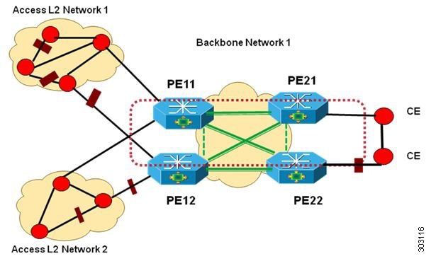
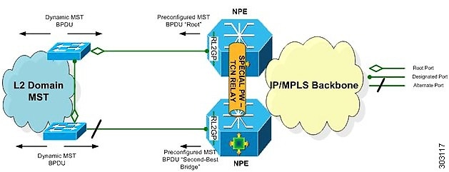
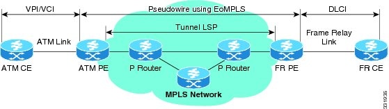
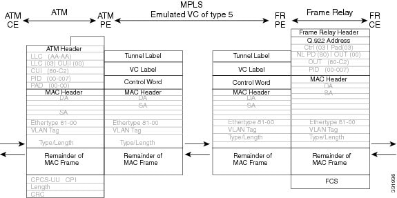
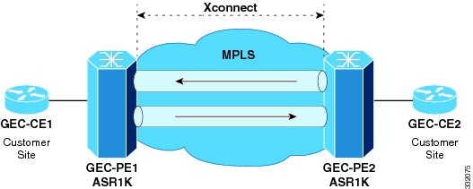
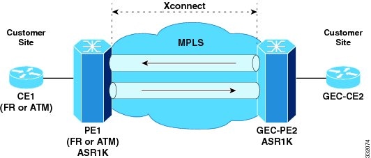

 Feedback