Feedback
Table Of Contents
If You Already Have a Cisco AS5800
LED Indicators and Alarm Buttons
Power Module Safety Features (2400W AC-Input Power Shelf)
2400W Power Shelf LED Indicators
Cisco AS5850 Product Overview
The Cisco AS5850 is a high-density, ISDN and modem WAN aggregation system that provides both digital and analog call termination. It is intended to be used in service provider dial point-of-presence (POP) or centralized enterprise dial environments.
The gateway components include hybrid trunk and port-handling cards (both functions are handled by different components in the same slot), dedicated port-handling cards, dedicated trunk cards, route switch controllers, power entry modules, and a blower unit to cool the chassis. An optional 2400W AC power shelf is also available. The gateway is designed with environmental monitoring and reporting functions to help maintain normal system operation and resolve adverse environmental conditions prior to loss of operation. If conditions reach critical thresholds, the system shuts down to avoid equipment damage from excessive heat or electrical current.
Downloadable software and microcode allow you to load new software images into Flash memory remotely, without having to physically access the universal gateway, for fast and reliable upgrades.
This chapter provides physical and functional overviews to familiarize you with your new Cisco AS5850. The chapter also contains physical descriptions of system hardware and major components and functional descriptions of component features.
Note
Descriptions and examples of software commands appear in this document only when they are necessary for installing the system hardware. For software configuration information, refer to the Cisco AS5850 Universal Gateway Commissioning Guidelines that shipped with your system, or the Cisco AS5850 Universal Gateway Operation, Administration, Maintenance, and Provisioning Guide. These documents are available on Cisco.com (http://www.cisco.com), by selecting:
Products and Services > Universal Gateways > Cisco AS5800 Universal GatewaysThis chapter contains the following sections:
•
If You Already Have a Cisco AS5800
If you already have a Cisco AS5800, the Cisco AS5850 should be easy to adjust to. The following major differences should be noted:
•
•
•
•
•
•
•
http://www.cisco.com/univercd/cc/td/doc/product/access/acs_serv/as5850/sw_conf/5850oamp/ index.htm.)
•
System Components
The following sections in this chapter describe the core system components:
The Cisco AS5850 is designed to be rack-mounted. A rack-mount kit is included with each Cisco AS5850. Each rack-mount kit provides the hardware needed to mount the chassis in a standard, 19-inch equipment rack or standard telco rack. If you plan to use a 23-inch equipment rack, you must provide your own brackets or shelves to accommodate the Cisco AS5850 and optional AC power shelf. For clearance requirements and rack-mount installation considerations, refer to the section
"Site Requirements" in Chapter 2, "Preparing for Installation."Figure 1-1 shows a front view of a Cisco AS5850 with the optional 2400W power shelf, and Figure 1-2 shows a rear view.
Figure 1-1 Cisco AS5850 with 2400W AC-Input Power Shelf—Front View
Note
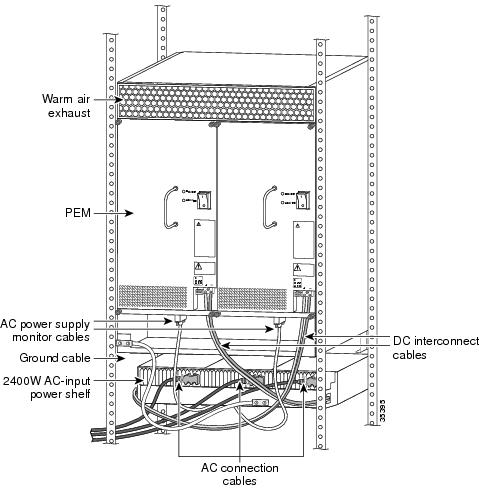
Figure 1-2 Cisco AS5850 with AC-Input Power Shelf—Rear View
Functional Overview
The Cisco AS5850 supports high-density dial aggregation and integrates with the Cisco AS5350 and Cisco AS5400 universal gateways for scaling your service provider network.
The Cisco AS5850 universal gateway also supports high availability of service through online insertion and removal (OIR) capabilities and redundant power modules that are hot swappable. All active components within the chassis support OIR, which allows components to be removed or replaced while the system is powered on. Feature cards can be busied-out through the software to avoid loss of calls.
The Cisco AS5850 is compatible with the Cisco Universal Gateway Manager (UGM) network management software. For more on Cisco UGM, see the "Network Management" section.
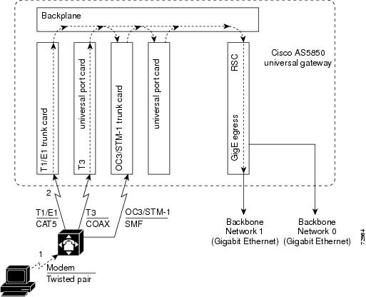
The Cisco AS5850 supports Channelized T1, E1,T3 PRI, and STM1 ingress interfaces that terminate ISDN and modem calls at DS0 granularity. Digital calls are terminated onboard the trunk card, and analog calls are sent to port handling resources on the same card or on other feature cards. As a result, any DS0 can be mapped to any HDLC controller or universal port. You can install multiple ingress interface cards of like types and configure the Cisco AS5850 for card or port level redundancy, depending on your needs.
Trunk and port handling cards are tied together using several time-division multiplexing (TDM) buses on the backplane. Each line card is also connected, through point-to-point packet buses, to a central switch on the Route Switch Controller (RSC) cards. The RSC cards transmit and receive packetized data across the IP network.
The Cisco AS5850 supports a split backplane configuration by using two RSC cards. In the classic-split configuration, the system operates as two separate universal gateways with each RSC controlling its own set of feature cards. In the handover-split mode, if one RSC fails, the other RSC takes control of the failed RSC's feature cards so their operation can continue. In the route processor redundancy (RPR+) mode, one RSC acts as the active RSC that controls all the resources in the chassis. The other RSC is the standby RSC and assumes control of the chassis if the active RSC fails. RPR+ enables a much faster switchover with fewer dropped calls than handover-split mode. For more information about the split backplane configuration, refer to the "Split Backplane" section.
The RSC card also provides clock and power control to the feature cards. Each RSC card contains a block of logic, referred to as the common logic, and system clocks. This block generates the backplane 4-MHz and 8-KHz clocks used for interface timing and for the TDM bus data movement. The common logic can use a variety of sources to generate the system timing, including a BITS input signal from the BNC connector on the RSC front panel. The clock source can also be telco office timing units extracted from the network ingress interfaces.
On the RSC card, only one common logic is active at any one time, which is identified by the CLK (clock) LED on the RSC card front panel. The active common logic is user-selectable and is independent from each RSC. This assures that if an RSC card needs replacing or if the slave RSC card becomes the master, clocking remains stable. The selected common logic should not be changed during normal operation unless related hardware failure is suspected or diagnosed.
You can install and upgrade software remotely, without affecting current system operation. You can also upload and download configuration files remotely, without affecting current system operation. Remote access is enabled by use of simple network management protocol (SNMP), by a Telnet session to a console port on the router shelf, through the World Wide Web (WWW) interface, or through use of the optional network management software.
The Cisco AS5850 can dynamically adjust any port to support any user configuration. Individual users can be authenticated as they connect to the system by use of one or more authentication servers using RADIUS and TACACS+ authentication protocols. Primary and backup authentication servers can define user authentication parameters using the user domain and the number called. User profile information can also be configured to include time of day, number of simultaneous sessions, and number of B-channels used.
When a remote user connects to the universal gateway using a modem or an ISDN line, the user is authenticated and establishes a session. Dynamic address assignment from an authentication server or static address assignment connects the user and has virtually no impact on service provider routing tables.
A remote LAN user can connect to the universal gateway using an ISDN line or asynchronous serial connection, be authenticated, and establish a session. In addition to dynamic or static address assignment, this connection requires the traditional Cisco IOS software support for different routing protocols on different ports simultaneously, with virtually no impact on service provider routing tables.
A dial wholesale customer can connect to a Cisco AS5850, then tunnel PPP (Point-to-Point Protocol) packet information to a retail service provider using dial Virtual Private Network (dial VPN).
For detailed system specification tables, refer to Appendix A, "Cisco AS5850 Specifications."
Traffic Flow
Figure 1-3 shows inbound connection flow for the Cisco AS5850.
Figure 1-3 Inbound DS0 Traffic Flow
A typical user connection flows as follows:
1.
2.
3.
4.
5.
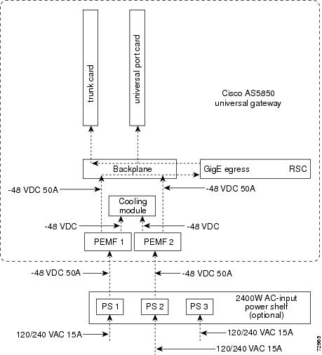
Power Flow
Figure 1-4 shows how power is distributed to various universal gateway field-replaceable units.
Figure 1-4 Power Distribution
Note
Network Management
The Cisco Universal Gateway Manager (Cisco UGM) configures and manages fault, performance, and security of the Cisco AS5850. Cisco UGM is a UNIX-based solution that can be run from a Cisco Element Management Framework (EMF) server, and also provides the following features:
•
•
•
•
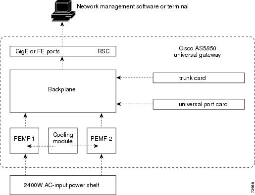
Figure 1-5 shows the flow of system management information for the Cisco AS5850.
Figure 1-5 System Management Information Flow
Cisco AS5850 Chassis
The Cisco AS5850 contains 14 slots (numbered 0 through 13 on the backplane) and can support trunk cards and universal port cards in slots 0 through 5 or 8 through 13. Slots 6 and 7 in the chassis are dedicated slots for the RSCs. There are two versions of the RSC, RSC and ERSC. ERSC has a faster CPU, more memory, and two Fast Ethernet ports. Metal guard pins on the backplane module prevent you from installing any other type of card in these two slots. The modular chassis supports online insertion and removal (OIR) and redundant power and includes environmental monitoring and feedback control.
Table 1-1 shows the possible trunk card configurations:
Note
The universal gateway uses CT1, CE1, CT3, or STM1 trunk interfaces that terminate ISDN and modem calls and break out individual calls from the appropriate telco services. Digital calls are terminated on the trunk card high-level data link control (HDLC) controllers, and analog calls are terminated on the universal ports on the trunk card, if available, or universal ports on another feature card. As a result, any DS0 can be mapped to an onboard HDLC controller or any universal port. You can install multiple ingress interface cards, which enables you to configure your systems as fully operative, port redundant, or card redundant, depending on your specific needs.
Clock Management
The RSCs also provide clock and power control to the feature cards. Each RSC contains a block of logic, referred to as the common logic, and system clocks. This block of logic can use a variety of sources to generate the system timing, including a T1, E1,T3, STM1, or BITS input signal (accepts only T1 or E1) from the BNC connector on the RSC front panel.
Only one common logic circuit is active at any one time, which is identified by the CLK (clock) LED on the RSC front panel. The active common logic is user-selectable and is independent from each RSC. This ensures that if an RSC needs replacing or if the slave RSC becomes the master, clocking remains stable. The selected common logic should not be changed during normal operation unless related hardware failure is suspected or diagnosed.
The configuration commands for the master clock specify the various clock sources and a priority for each source. Together these commands define a list, ordered by priority, of the clock sources used to generate the master clock. The prioritized list, configured on the router shelves, is passed to and stored by the RSC providing the active clock. In the event of failure of the highest-priority clock source, the RSC switches to the source with the next-highest priority.
With a split backplane, the clock sources can be configured on either of the RSCs. Typically a router configures clock sources only from the slots that it owns; clock sources can be configured from other slots, but they are ignored. On the universal gateway, all valid clock source configurations need to be known to the RSC providing the clock, including the clock source configurations on the other RSC.
An error condition can arise if a clock input on one RSC is configured to have the same priority as a clock input configured on the other RSC. However, the command is not rejected, because the values configured on the other RSC may not be known. Warning messages are issued to both RSCs when this condition is detected. Two clock inputs specified with identical priorities both go into the ordered list of clock sources, but the one received first by the RSC providing the active clock is assigned a higher priority.
The show chassis clocks command shows all configured clock sources, even those from un-owned trunk cards. Only one RSC can provide the master clock; however, backup clock sources might need to be configured for all trunk cards present (regardless of which RSC owns them).
Note
Split Backplane
The split backplane configuration of the Cisco AS5850 platform increases bandwidth by using two RSCs. The dual RSCs serve as the interfaces between the split Cisco AS5850 gateway and the external network. Split backplane configuration requires two RSC cards. For more information on hardware and software configuration needed for a split backplane configuration, refer to the Cisco AS5850 Operations, Administration, Maintenance, and Provisioning Guide, available online at: http://www.cisco.com/univercd/cc/td/doc/product/access/acs_serv/as5850/sw_conf/5850oamp/ index.htm
If your gateway contains two route switch controller (RSC) cards, you can configure your Cisco AS5850 into one of three modes: classic split, handover split, or route processor redundancy (RPR+).
•
•
•
Note
OIR Events
Split backplane configurations are managed by having the slots that are owned by one RSC appearing to the other RSC as empty slots. An RSC is informed of OIR events by messages that are sent to the RSC when a card is inserted in or removed from a slot. An RSC sends messages only for OIR events that occur in slots that it owns. The packet switch on each RSC is configured to ignore traffic from cards in un-owned slots.
Card Bootup
When a feature card starts running, it sends a message to the RSCs. The RSCs determine whether they are the master for that slot. Only the RSC that owns the slot containing the feature card responds to the message. The feature card accepts firmware and a bootstrap image from that RSC and configures itself to communicate through that RSC. The first time an RSC is inserted, it sends an inventory request indicating that all feature cards should be reloaded. In split backplane mode, the final feature card image is downloaded by each card from the RSC that owns it.
Slot Ownership Arbitration
The Cisco AS5850 operates in a default split backplane mode. Currently, the RSC in slot 6 automatically owns all cards in slots 0 through 5, and does not receive inventory messages from cards present in slots 8 through 13. The RSC in slot 7 automatically owns all cards in slots 8 through 13, and does not receive inventory messages from cards present in slots 0 through 5.
TDM Resource Allocation
The various kinds of feature cardss (FCs) that can be placed in the chassis connect to one another using Time-Division Multiplexing (TDM) buses in the chassis backplane. The Cisco AS5850 has a total of 4 such buses, each bus supports 2048 DS0s, giving the backplane a total DS0 capacity of 8192 (numbered from 0 to 8191).
The TDM management software on each of the RSCs controls the allocation of the backplane DS0s. Allocation starts with the fourth (i.e. last) backplane bus and finishes with the first. Allocation will only move onto a new backplane bus when all the DS0s on the currently-used backplane bus are in use. Within a given bus, allocation begins at the lowest DS0 and progresses to the highest DS0. Once a DS0 has been allocated, used and released, it is put back onto the end of a queue of DS0s for the bus to which it belongs. Thus, a DS0 will only be re-used when all the other free DS0s on its backplane bus have been used. After a long period of operation, the ordering of DS0s within a particular DS0 queue will effectively be random.
In systems with two RSCs, the way the RSC uses the backplane buses will depend on the mode the system is operating in. Sometimes one RSC will control all the backplane DS0s and sometimes their use will be divided between the RSCs.
Environmental Monitoring
Environmental monitoring for the full chassis is carried out by both RSCs. This means that warnings about overheating cards go to both RSCs, regardless of which one owns the slot. Sending the warnings to both RSCs reduces the chance of an environmental problem going unreported.
For detailed chassis specification tables, refer to Appendix A, "Cisco AS5850 Specifications."
Field-Replaceable Units
The Cisco AS5850 is designed to make component removal and replacement easy. This section describes the Cisco AS5850 field-replaceable units (FRUs).
Table 1-2 describes available Cisco AS5850 FRUs that can be ordered as spares.
For information about the feature cards used in the Cisco AS5850, refer to the Cisco AS5850 Universal Gateway Card Guide that shipped with your system. For information about other FRUs, review the rest of this chapter, or for detailed specification tables, refer to Appendix A, "Cisco AS5850 Specifications."
Feature Cards
For information about the feature cards used in the Cisco AS5850, refer to the Cisco AS5850 Universal Gateway Card Guide that shipped with your system. For information about other FRUs, review the rest of this chapter, or for detailed specification tables, refer to Appendix A, "Cisco AS5850 Specifications"
Cooling Module
The cooling module in the Cisco AS5850 monitors the internal operating temperatures and maintains acceptable cooling parameters. The cooling module contains 12 variable-speed impeller fans in three banks of four fans, and a controller card that performs the following functions:
•
The controller card contains temperature sensors, that monitor internal air temperature within the chassis. These temperature sensors, along with other system maintenance sensors, can detect areas exceeding the temperature set point.
•
Fan speed is controlled by a microprocessor on the fan controller card within the cooling module, and also by software. If air temperature within the chassis exceeds the acceptable operating range, the fan controller card increases the fan speed in an attempt to control the temperature. If temperatures continue to rise, the controller card linearly increases fan speed until the fans reach full speed. If acceptable operating temperatures are still unobtainable, the system environmental monitor shuts down all internal power, thus preventing equipment damage from excessive heat.
During normal operation, the fans "load-share" to provide cooling. If one of the twelve fans fails, a warning message displays on your console screen. The controller card then increases the speed of the remaining operative fans to maintain acceptable temperature levels.
When all fans are operating normally, fan speed is 1600 rpm. As ambient air temperature increases, fan speed increases accordingly. Thus, if one of the fans becomes inoperative, the remaining fans increase fan speed to 2400 rpm.
•
The cooling module supports OIR, which means that you can remove and replace the cooling module while the system is operating; system operation will not be affected. Normal cooling module replacement should take about 30 seconds. If you expect the replacement process to exceed 1 minute, you should shut down the system.
The cooling module is located directly above the feature cards. You install the cooling module into the front of the chassis where it plugs directly into the PEMFs. Figure 1-1 on shows the location of the cooling module in a fully configured Cisco AS5850 chassis, as viewed from the front of the system.
For detailed specification tables, refer to Appendix A, "Cisco AS5850 Specifications."
Route Switch Controller Card
The route switch controller (RSC) card is the main processor card for the universal gateway. There is also an enhanced route switch controller (ERSC) that has a faster CPU, more memory and two Fast Ethernet ports for network management. Both cards perform the following functions:
•
•
•
•
•
•
Install the RSC card in the Cisco AS5850 in either slot 6 or slot 7. The card plugs directly into the backplane.
The RSC card consists of the following components:
•
–
–
•
•
•
•
•
•
•
For detailed specification tables, refer to Appendix A, "Cisco AS5850 Specifications."
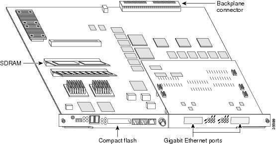
Figure 1-6 shows the RSC components.
Figure 1-6 RSC Components
Note
LED Indicators and Alarm Buttons
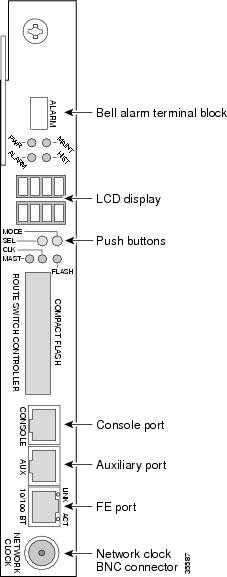
The RSC front panel contains several LEDs, push buttons, LCDs, and connectors.
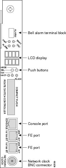
Figure 1-7 and Figure 1-8 show the RSC front panel LEDs.
Figure 1-7 RSCFront Panel
Figure 1-8 ERSC Front Panel
Table 1-3 describes the RSC front panel LEDs and LCDs.
1 A major alarm condition includes RSC failure, backplane failure, fan failure, power module failure, feature card failure, or conditional environmental thresholds.
2 A minor alarm condition includes modem SIMM failure, HDLC controller failure, trunk line failure, or conditional environmental thresholds.
Figure 1-7 shows the RSC front panel push buttons, Table 1-4 describes push button actions, and Table 1-5 describes options for those actions.
Figure 1-7 shows the RSC front panel ports, and Table 1-6 describes the port functions.
Warning
Note
50 VA Power.
Common Logic Interface
Each RSC card contains a block of logic referred to as the common logic and system clocks. This block generates the backplane Stratum compliant 4-MHz and 8-kHz clocks used for interface timing and for the TDM bus data movement. The common logic can use a variety of sources to generate this system timing, including a T1 or E1 signal input from the BNC connector on the RSC front panel.
Only one common logic is active at a time, identified by the CLK LED on the RSC card front panel. The active common logic is user-selectable and is independent from each RSC card. This assures that if you need to replace an RSC, or if the slave RSC becomes the master, clocking remains stable. The selected common logic should not be changed during normal operation unless a hardware failure is suspected or diagnosed in the RSC card.
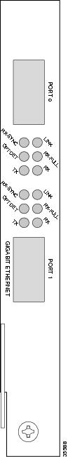
Gigabit Ethernet Egress
The RSC has dual gigabit Ethernet interfaces (See Figure 1-9.) Table 1-7 describes the gigabit Ethernet interface LEDs, and Table 1-8 details the pinout for the connector.
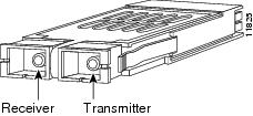
You can configure the two gigabit Ethernet ports with 1000BASE-SX or1000BASE-LX laser modules, known as gigabit interface converters (GBICs.) GBICs are hot-swappable input/output devices that plug into a Gigabit EtherChannel module, linking the module with the fiber-optic network (See Figure 1-10.) The GBICs fit through cutouts in the front of the module and plug into connectors on the module. You can install any combination of supported GBICs. Supported GBICs are listed in Table 1-9.
Note
Figure 1-9 RSC Gigabit Ethernet Egress Interfaces
Figure 1-10 GBIC Module
DC-Input Power Entry Module
The Cisco AS5850 is equipped with two power-entry modules (PEMFs), which accept DC-input power either from your site DC source or from an optional AC-input power shelf, and distribute -48 VDC to -60 VDC power to the chassis components using the backplane. The PEMFs provide power redundancy and load-sharing; however, a single PEMF can power a fully configured system. The PEMF also contains a passive DC power filter, which includes a broadband electromagnetic interference (EMI) filter and circuitry for monitoring power coming into the chassis.
Note
The PEMFs are cooled by system airflow, which flows from the top to the back of the chassis. The front and sides of the PEMFs are perforated for minimum airflow restriction.
The PEMFs support the following functions:
•
The DC-input power supply provides redundant power by design. During normal operation, the two PEMFs provide system power simultaneously (load share). When you remove one PEMF, the remaining PEMF immediately ramps up to provide full power and maintain uninterrupted system power.
•
A 24-pin connector monitors system environmental status and communicates this status from each PEMF using the maintenance bus (Mbus). Table 1-10 lists connector pins supporting system status signals.
•
The DC-input power supply is designed to prevent any energy hazard during operation. DC power is first routed to a circuit breaker, followed by a surge protector. In addition, an isolation diode circuit protects against possible DC-input failure.
The DC-input power supply monitors analog output voltage and current. The battery side of the DC input is equipped with a 60A circuit breaker, which trips if current reaches peak parameters for 2 seconds. The DC-input power supply circuits are described in Table 1-11.
If a PEMF is not properly seated in the Cisco AS5850 backplane, an electronic circuit, or interlock, trips a breaker in the PEMF and terminates power to the output connectors. This same interlock provides reverse polarity protection when the system is powered off.
Note
50 VA Power.•
The PEMFs provide relay outputs for standard central office bell alarms. These bell alarm contacts are available on a terminal plug mounted on the PEMF front panel.
•
The PEMFs support OIR, which means that you can remove or replace a PEMF while the system is operating; system operation is not affected. Only qualified personnel should OIR a PEMF.
•
The PEMF first receives -48 VDC power using analog isolation circuits. The DC power passes through a broadband EMI filter, then passes to a DC-to-DC converter on the RSC, where it is converted and then routed back to the backplane for distribution to the other cards. A single PEMF supports a fully configured chassis.
•
The PEMF contains the environmental maintenance bus (Mbus) module with a logic card, which carries monitor signals throughout the chassis by way of two 10-pin molex MiniFit connectors.
There are no connectors accessible from the front of the PEMF; however, a DB-9 connector at the base of the PEMF (visible only from below the chassis) connects a monitor cable to an optional AC-input power shelf.
The PEMFs are located on the rear of the universal gateway. Figure 1-2 shows the location of the PEMFs as viewed from the rear of the chassis.
The PEMFs contain two LEDs on the front panel—POWER and MISWIRE. The POWER LED indicates that input voltage is present and the PEMF circuit breaker is on; the MISWIRE LED should remain off, but comes on if the two DC conductors entering the PEMF DC-input power terminal block (see Figure 1-2) are reversed. If the POWER LED does not light, one of the output voltages is not present on the PEMF (-48V, 5.1V, 1.6V).
For detailed specification tables, refer to Appendix A, "Cisco AS5850 Specifications."
2400W AC-Input Power Shelf
The 2400W AC-input power shelf includes three 1200-watt (W) AC-input power modules that plug into a common power backplane in the 2400W AC-input power shelf. Two 1200W AC-input power modules are capable of powering a fully configured Cisco AS5850. The third power module provides full redundancy.
During normal operation, the three AC-input power modules provide automatic load-sharing, with each power module supporting 33 percent of the power load. When you remove one of the AC-input power modules, the remaining power modules immediately ramp up to full power and maintain uninterrupted system power.
Note
Each AC-input power module is powered on automatically when it is plugged in and receiving power. Ejector lever/handles secure each power module to the backplane connectors and allow you to remove and replace the power modules with ease.
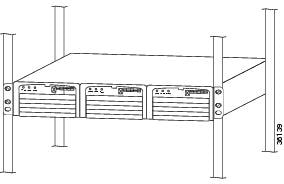
Figure 1-11 shows a front view of a 2400W AC-input power shelf installed in a four-post rack.
Figure 1-11 Cisco AS5850 2400W AC-Input Power Shelf—Front View
The 2400W AC-input power shelf is two rack units high (3.5 in. [8.88 cm]) and mounts underneath the chassis in a standard 19-inch 4-post or telco-type rack assembly.
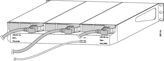
All cable connections for AC-input power, DC-output power, and status signals are made from the 2400W AC-input power shelf rear. (See Figure 1-12.) Three modular power cables connect each AC-input power module to the site AC-input power source. Two DC-interconnect cables provide DC-output power to the chassis. Two monitor cables provide a status signal connection to the PEMF maintenance bus (Mbus), which monitors voltage tolerance levels, temperature conditions, and power failure in the enhanced AC-input power shelf. A grounding cable provides a ground connection from the 2400W AC-input power shelf to the chassis.
Figure 1-12 shows a rear view of a 2400W AC-input power shelf before installation.
Figure 1-12 Cisco AS5850 2400W AC-Input Power Shelf—Rear View
For detailed specification tables, refer to Appendix A, "Cisco AS5850 Specifications."
Power Module Safety Features (2400W AC-Input Power Shelf)
The power modules in the enhanced 2400W AC-input power shelf have the following safety features:
•
•
•
•
Internal monitoring data is passed to the chassis through the maintenance bus (Mbus) monitoring system. You can view this data through a terminal connected to the RSC console port. The command to display the monitoring information is described in the Cisco AS5850 Universal Gateway Operation, Administration, Maintenance, and Provisioning Guide, available online at: http://www.cisco.com/univercd/cc/td/doc/product/access/acs_serv/as5850/sw_conf/5850oamp/ index.htm
2400W Power Shelf LED Indicators
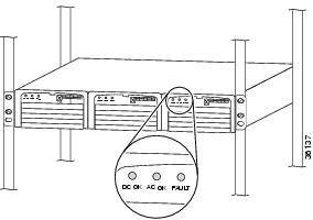
The 2400W AC-input power shelf includes three LEDs that are located on the front of each power module for the 2400W AC-input power shelf. (See Figure 1-13.)
Figure 1-13 2400W AC-Input Power Module LEDs
The power module LEDs for the enhanced AC-input power shelf are summarized in Table 1-12.
Power Requirements
The Cisco AS5850 ships configured for either AC-input or DC-input power with loadsharing, depending on your order.
AC-Input Power Specifications
The Cisco AS5850 accepts AC-input power using a separate, self-contained AC-input power shelf, which converts AC-input power into DC output for use by the universal gateway. The AC-input power shelf is rack-mounted and has a safety cover that shields the electrical connections in the power shelf rear.
The AC-input to DC-output connection supplies -48 VDC-output power to the PEMFs. Power flows through the filter module to the backplane, where it is distributed to the RSC and feature cards.
DC-Input Power Specifications
The PEMFs provide -48 VDC power, which is distributed from the PEMF to the chassis backplane. The analog isolators in the filter module are provided with 15 VDC. No damage occurs to the PEMFs if any or all outputs have no load (no load occurs when there are no cards plugged into the backplane), or if the maximum input voltage is exceeded; however, input voltages that exceed 75V eventually trip the PEMF 60A circuit breaker, and you might have to reset the breaker.
The Cisco AS5850 supports several types of logic cards with varying power requirements. As a result, each logic card DC-to-DC converter system is isolated from the distributed -48 VDC power, creating a more stable distributed power system.
Online Insertion and Removal
The Cisco AS5850 supports online insertion and removal (OIR), which allows you to remove and replace a field-replaceable unit (FRU) while the system is operating, without affecting system operation.
Note
Each FRU contains female connectors that connect to the system backplane. Each male backplane connector comprises a set of tiered pins in three lengths. The backplane pins send specific signals to the system as they make contact with the card connectors. The system assesses the signals it receives and the order in which it receives them to determine whether to initialize a startup or shutdown procedure.
Each RSC card and feature card is designed with two ejector levers to be used when you install or remove a card. The function of the ejector levers (see Figure 3-4) is to align and securely seat the card connectors in the backplane and facilitate the installation and removal process.
Do not force the RSC cards or feature cards into the slot, because this can damage the card connector pins if they are not aligned properly with the card connectors.
To avoid erroneous failure messages, you must allow at least 15 seconds for the system to reinitialize and note current interface configurations before you remove or insert another RSC card or feature card in the chassis.
Note
index.htm