Feedback
Table Of Contents
Preparing the Cisco AS5850 for Rack-Mounting
Removing the DC Power-Entry Modules
Removing Trunk and Port or RSC Cards
Installing the Rack-Mount Brackets on the Chassis
Mounting Brackets for an Offset Telco Rack Installation
Connecting to an AC Power Source
Unpacking and Preparing the AC Power Supply
Installing the Power Shelf in the Rack
Installing the Universal Gateway in the Rack
Replacing the Universal Gateway Components
Connecting Cables from the AC-Input Power Shelf
Connecting to a DC Power Source
Connecting the CT1/E1 Trunk Card
Connecting the SDH/STM-1 Trunk Card
Connecting RSC Gigabit Ethernet Cables
Connecting to the RSC Console and Auxiliary Ports
Installing the Cisco AS5850
This chapter explains the procedures for installing the universal gateway. Installation involves the following tasks in the following order:
1.
Removing the Cisco AS5850 from its shipping container
2.
3.
4.
5.
6.
7.
8.
9.
10.
The estimated time to install the universal gateway hardware is between 2 and 3 hours.
Note
This chapter assumes that you are installing the universal gateway manually. If you have access to a forklift or hydraulic equipment during the installation, you can omit certain steps, which are specified later in this chapter.
Removing the Packaging
Place the Cisco AS5850 as close as is practical to the rack you intend to install it in before removing the shipping container. To remove the shipping package for the Cisco AS5850, follow these steps:
Step 1
Step 2
Step 3
Step 4
Step 5
Step 6
Preparing the Cisco AS5850 for Rack-Mounting
The Cisco AS5850 is shipped with the cooling module and all server cards (trunk and modem cards) and route switch controller cards installed in the chassis. Fully loaded, the Cisco AS5850 weighs 221 lb (100.2 kg).
Before installing the Cisco AS5850 in an equipment rack, Cisco recommends that you remove the cooling module, DC PEMFs, and cards from the universal gateway, and then reinstall them after the chassis is mounted in the rack. (If you are using a forklift or other machinery to lift the universal gateway, you can omit this process.)
After you remove the cooling module, PEMFs, and the installed cards, mount the rack-mount brackets on the universal gateway chassis and install the chassis in the rack.
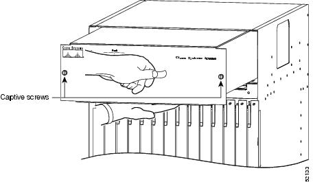
Removing the Cooling Module
Caution
To remove the cooling module, complete the following steps:
Step 1
Step 2
Step 3
Step 4
Step 5
Note
Figure 3-1 Removing the Cooling Module
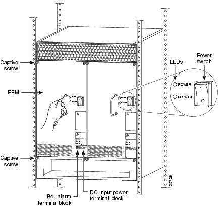
Removing the DC Power-Entry Modules
To remove the DC PEMFs, complete the following steps:
Step 1
Step 2
Figure 3-2 Removing and Replacing a PEMF
Note
Step 3
This completes the PEMF removal process. Proceed to "Removing Trunk and Port or RSC Cards."
Removing Trunk and Port or RSC Cards
To remove cards, follow these steps:
Caution
Step 1
Step 2
Caution
Step 3
Step 4
Caution
Figure 3-3 Using the Ejector Levers
Step 5
Figure 3-4 Removing Cards
Step 6
Step 7
Step 8
You are now ready to install the rack-mount brackets on the chassis. Proceed to the following section, "Installing the Rack-Mount Brackets on the Chassis."
Installing the Rack-Mount Brackets on the Chassis
Bracket placement depends on the type of rack you use to install your universal gateway. This section describes both a 4-post rack installation and a telco rack installation.
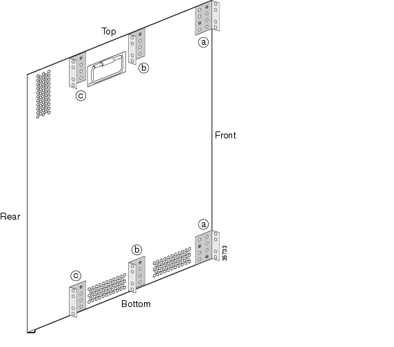
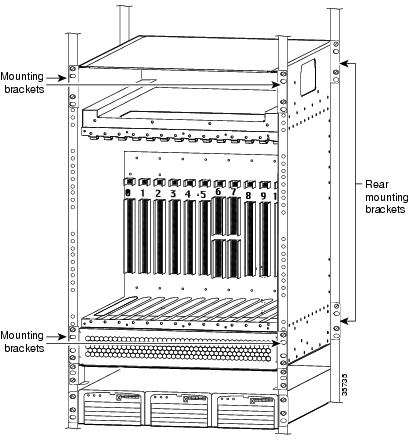
Threaded holes on the chassis sides are strategically located to position and mount bracket hardware. The threaded hole closest to the front of the chassis are used for flush-front mounting (see Figure 3-5, position, a, Top and a, Bottom). If you are mounting the universal gateway in a 4-post rack, you have the option of using four brackets (two on each side) placed toward the rear of the chassis (see Figure 3-5, position, c, Top and c, Bottom) to support the chassis in the back. If you are mounting the universal gateway in a telco rack, you need to offset the chassis five inches beyond the rack center post and use two brackets (see Figure 3-5, position, b, Top and b, Bottom).
Figure 3-5 Bracket Mounting Hole Positions
If you are installing your universal gateway in a telco rack, proceed to the following section, "Mounting Brackets for an Offset Telco Rack Installation."
If you are installing your universal gateway in a 4-post rack or front-mounting the server on a non-offset configuration, you need to install brackets on the chassis front before putting it in the rack. (See Figure 3-5, positions a, Top and a, Bottom.) The rear brackets must be installed after the server is already front mounted in the rack. If the rear brackets are mounted at the same time as the front brackets, the server will not fit in the rack.
4-Post Rack Installation
To install the rack-mount brackets on the universal gateway for a flush-front or 4-post rack installation, complete the following steps:
Step 1
Step 2
Step 3
Step 4
Step 5
Step 6
Note
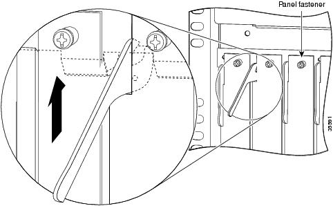
Mounting Brackets for an Offset Telco Rack Installation
To install the rack-mount brackets on the universal gateway for an offset telco rack-mount configuration, complete the following steps:
Step 1
Step 2
Step 3
Step 4
Step 5
Step 6
Connecting to an AC Power Source
If your site has access to an AC power source only, you need to install the optional 2400W AC-input power shelf to convert to DC-input power for the universal gateway.
The AC-input power shelf is an optional component of the Cisco AS5850 and is used to convert AC-input power into DC-output power for the DC-powered Cisco AS5850. The AC-input power shelf contains three AC-input power supplies, and DC output cables and power supply monitoring cables are attached to the shelf chassis before the power supply is shipped.
This section explains how to attach the AC-input cables and ground cable and rack-mount the AC-input power shelf. For detailed cabling specification tables, refer to "Cisco AS5850 Specifications."
Parts Required
You need the following tools and parts to rack-mount the power shelf:
•
•
•
•
•
•
•
•
•
•
•
•
•
To connect the power cables, proceed to the following section "Unpacking and Preparing the AC Power Supply."
Unpacking and Preparing the AC Power Supply
It is possible to mount the cable on the AC power supply after it has been rack-mounted, but given the limited space in and around many equipment racks, Cisco recommends that you mount the cables before rack-mounting the AC power supply. Figure 3-6 shows cables mounted on a standard AC power supply, but the process is the same for the enhanced power supply. To unpack the power shelf chassis and mount the AC power supply AC-input and ground cables, complete the following steps:
Step 1
Step 2
Step 3
Step 4
Note
Step 5
Caution
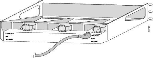
Figure 3-6 Mounting AC-input Cables on the Rear of the AC Power Shelf
The power shelf has three IEC 60320 Type C20 power inlets. If you are not using one of the standard Cisco power cords designated for your country, choose one that has an IEC 60320 Type C19 connector on one end and the appropriate country-specific plug on the other end. The power cord should be rated at least 15 A at low voltages (100 to 120 VAC) and at least 10 A at high voltages (200-240 VAC).
Step 6
Step 7
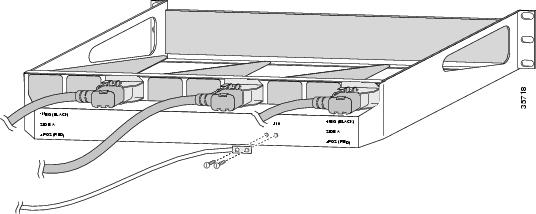
Figure 3-7 Mounting the Ground Cable on the Rear of the AC Power Shelf
Installing the Power Shelf in the Rack
Install the power shelf in the rack by securing the permanent mounting flanges to two posts or mounting strips in the rack, using the slotted mounting screws provided. Because the mounting flanges support the weight of the entire power shelf, be sure to use at least two slotted screws per mounting flange.
Caution
Caution
The power shelf ships without power supplies mounted in their intended bays. There is a metal spacer installed in the power supply bays to maintain the chassis' proper shape until the chassis is installed in a rack. To install the power shelf in the rack, follow these steps:
Step 1
Step 2
Step 3
Step 4
Step 5
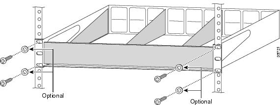
Figure 3-8 Mounting the 2400W Power Shelf
Step 6
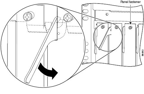
To install the power supplies, follow these steps:
Step 1
Step 2
Step 3
Caution
Step 4
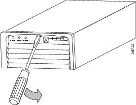
Figure 3-9 Releasing the Ejector Lever
Step 5
Figure 3-10 Installing a Power Supply
Step 6
Figure 3-11 Securing the Ejector Lever
Step 7
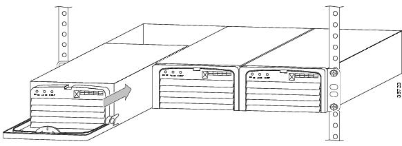
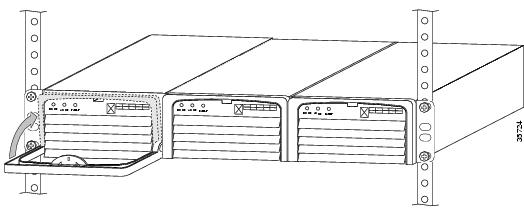
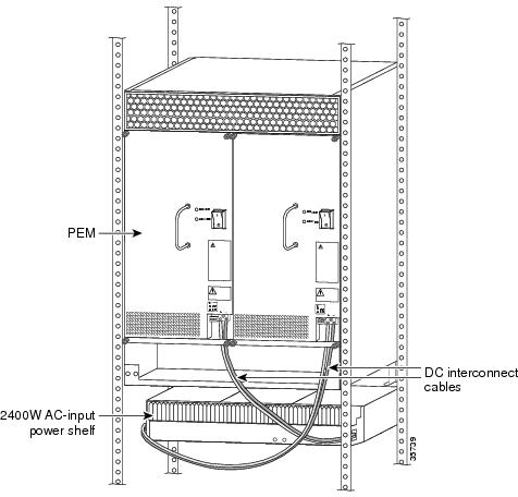
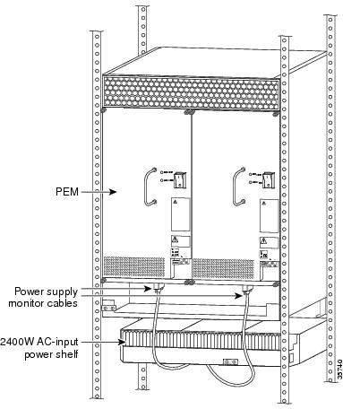
Figure 3-12 illustrates the AC-input power shelf installed in a 4-post rack.
Figure 3-12 AC-Input Power Shelf Installed in a 4-Post Rack
Installing the Universal Gateway in the Rack
One person cannot install the universal gateway chassis in the rack unassisted. Two or preferably three people are needed.
To secure the rack-mount brackets to the posts or mounting strips in the rack, you must use the slotted mounting screws provided. Because the brackets support the entire weight of the chassis, be sure to use at least two slotted screws per bracket.
Be sure that you have the universal gateway prepared as described in the "Preparing the Cisco AS5850 for Rack-Mounting" section before installing the chassis in the rack. Mounting brackets should have been installed as described in the "Installing the Rack-Mount Brackets on the Chassis" section. To install the universal gateway chassis in the rack, complete the following steps:
Caution
Step 1
Step 2
Note
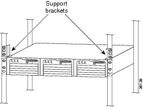
The AC-input power supply will not support the weight of the Cisco AS5850 chassis. To prevent damage to the power supply or any other components already in the rack, you must use the support brackets as shown.
Figure 3-13 Mounting Support Brackets for the Cisco AS5850
Step 3
Warning
Step 4
Note
Step 5
This completes a front-mounted or telco-rack installation. To complete the universal gateway rack installation for a 4-post installation, mount the rear set of brackets to the chassis. Proceed to the following section "Mounting the Rear Brackets."
Mounting the Rear Brackets
This section explains how to mount the rear brackets for 4-post rack installations.
Note
For a 4-post rack-mount installation, mount the optional rear brackets to the sides of the chassis as follows:
Step 1
Step 2
Step 3
Step 4
Step 5
Step 6
Step 7
Step 8
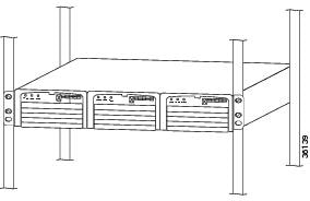
Figure 3-14 Cisco AS5850 Installed in a 4-Post Rack
This completes the universal gateway rack-mounting procedures for a 4-post rack. Proceed to the following section "Replacing the Universal Gateway Components."
Replacing the Universal Gateway Components
This section contains instructions for replacing the universal gateway components.
Cooling Module
Caution
Replace the cooling module in the universal gateway as follows:
Step 1
Figure 3-15 Replacing the Cooling Module
Step 2
Step 3
Step 4
Power-Entry Modules
To reinstall the PEMFs, complete the following steps. (Refer to Figure 3-16 to locate the PEMFs in the universal gateway.)
Step 1
Step 2
Step 3
Step 4
Step 5
Figure 3-16 Replacing a PEMF
This completes the procedure for replacing a PEMF in the universal gateway.
Cards
Timesaver
Note
Note
Caution
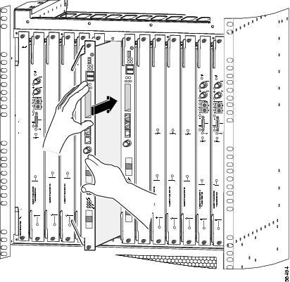
Replace the cards in the chassis as follows:
Step 1
Step 2
Step 3
Figure 3-17 Extend the Ejector Levers
Step 4
Figure 3-18 Seating the Card in the Backplane
Step 5
Figure 3-19 Seating the Card with the Ejector Levers
Tip
Step 6
Caution
Step 7
Caution
Step 8
Connecting Cables
When the universal gateway has been rack-mounted and all components have been reinstalled into the chassis, DC power connections from a DC source or AC-input power shelf can be connected to the universal gateway. The monitor connection from an AC-input power shelf should also be connected at this stage. The following sections assume the use of the optional AC-input power shelf. If your installation uses a DC power source, see the "Connecting to a DC Power Source" section.
Connecting Cables from the AC-Input Power Shelf
You need to connect all cables between the AC-input power shelf and the universal gateway before you connect the power shelf to your AC power source. You also need to install the provided electrical connection safety cover at the rear of the power shelf before you power up the system. For detailed cabling specification tables, refer to "Cisco AS5850 Specifications."
Warning
Warning
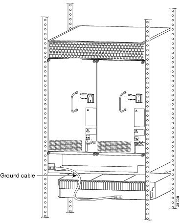
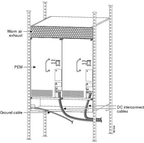
To attach the ground cable between the AC-input power shelf and the chassis, complete the following steps:
Step 1
Figure 3-20 Attaching the Ground Cable
Step 2
Step 3
Step 4
Step 5
Step 6
Figure 3-21 Attaching the Power Cables to a 2400W Power Shelf
Note
Step 7
Figure 3-22 Attach the Monitor Cables
Step 8
Step 9
Note
This completes the AC power cable installation.
Connecting to a DC Power Source
The following sections are for installations using a direct DC power source, without an AC-input power shelf.
Note
To connect to a DC power source, follow these steps:
Warning
Warning
Warning
Step 1
Figure 3-23 Cisco AS5850—Rear View (DC install shown)
Step 2
Step 3
Note
Caution
Step 4
Step 5
Step 6
Note
Warning
Warning
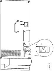
Figure 3-24 DC Terminal Block on the PEMF
Step 7
Step 8
Note
Connecting Trunk Card Cables
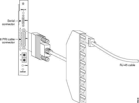
The trunk card provides RJ-45 receptacles for channelized T1 or E1 lines, SFF-LC, SM optical connectors for SDHHSTM-1 connections, or BNC connectors for T3 trunk lines.
Warning
Warning
Warning
Warning
Warning
Warning
Warning
Connecting the CT1/E1 Trunk Card
Note
To connect T1 or E1 trunk lines, follow these steps:
Step 1
(See Figure 3-25.)Figure 3-25 Connecting the CT1/E1 Trunk Card RJ-45 Cables
Step 2
Step 3
Step 4
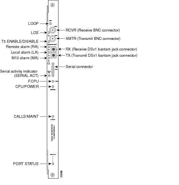
Connecting the T3 Trunk Card
To connect the T3 lines, follow these steps:
Step 1
Figure 3-26 CT3 Trunk Card Front Panel
Step 2
For more information about trunk cables and trunk cards, refer to the Cisco AS5850 Universal Gateway Card Guide.
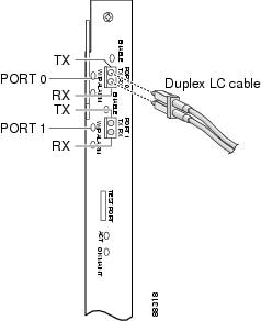
Connecting the SDH/STM-1 Trunk Card
The SDH/STM-1 trunk card has two SFF-LC, SM optical connectors.
Follow these steps to connect an SDH/STM-1 trunk card to the network:
Warning
Step 1
Note
Figure 3-27 Connecting the SDH/STM-1 Trunk Card
Step 2
Note
Note
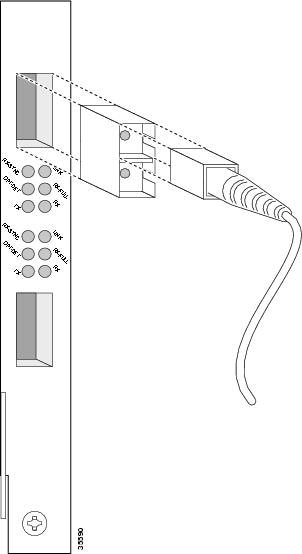
Connecting RSC Gigabit Ethernet Cables
Egress connections to LANs and WANs are made through the gigabit Ethernet interfaces on the RSCs in slots 6 and 7 (see Figure 3-28).
Gigabit Ethernet ports are labeled port 0 and port 1 and use a Cisco GBIC connector.
Figure 3-28 RSC Egress Interfaces
Connecting to the RSC Console and Auxiliary Ports
A DCE-mode console port and a DTE-mode auxiliary port are located on the RSC. The console port is an RJ-45 receptacle for connecting a data terminal, which you use to run the initial setup script and bring up the Cisco AS5850. The auxiliary port is an RJ-45 receptacle for connecting a modem or other DCE device (such as a CSU/DSU or other router) to the universal gateway.
Note
Note
Before connecting a terminal to the console port, configure the terminal to match the router console port as follows: 9600 baud, 8 data bits, no parity, 2 stop bits (9600 8N2). You need an RJ45 console cable to connect the terminal to the console port. After you establish normal server operation, you can disconnect the terminal.
You must supply your own interface cable between the auxiliary port and the equipment you are connecting. Refer to "Cisco AS5850 Specifications," for console and auxiliary port pinouts.
This completes the procedures for installing and cabling your Cisco AS5850. To start the universal gateway, proceed to Chapter 4, "Powering On the Cisco AS5850 and Observing Initial Startup Conditions."