Downloads |
 Feedback Feedback
|
Table Of Contents
Preparing to Install the Cisco 7304 Router
Electrical Equipment Guidelines
Preventing Electrostatic Discharge Damage
General Tabletop or Workbench Installation
Rack-Mounting a Cisco 7304 Router
Attaching the Chassis Rack-Mount and Cable-Management Brackets
Installing Rack-Mount Brackets on the Front of the Chassis
Attaching the Cable-Management Brackets
Installing Rack-Mount Brackets on the Rear of the Chassis
Installing the Chassis in the Rack
Attaching a Chassis Ground Connection
Connecting Console and Auxiliary Port Cables
Connecting Gigabit Ethernet Cables on the NSE-100
NSE-100 Multimode and Single-Mode Optical Fiber Cables
Connecting the GBIC Interface Cables on the NSE-100
Connecting Gigabit Ethernet Cables on the NPE-G100 and the NSE-150
Intra-Building Lightning Protection
NPE-G100 Multimode and Single-Mode Optical Fiber Cables
NSE-150 Multimode and Single-Mode Optical Fiber Cables
Connecting the Gigabit Ethernet SFP Module and Cables
Attaching the Mode-Conditioning Patch Cord for the NSE-100, NSE-150, or NPE-G100
Securing the Line Card and I/O Cables
Removing and Replacing a Processing Engine
Removing the Slot Divider for a Redundant Configuration
Removing and Replacing a Power Supply
Powering Down the Router and Disconnecting Input Power
Powering Down an AC-Input Power Supply
Powering Down a DC-Input Power Supply and Removing the DC-Input Leads
Reconnecting AC-Input Power and Powering Up the Router
Reconnecting DC-Input Power and Powering Up the Router
Removing and Replacing the Fan Module
Installation and Maintenance
This chapter explains how to install a Cisco 7304 router in a rack in a general tabletop or workbench installation, how to attach cables, and how to power on the router. Additionally, this chapter contains replacement instructions for replacing the network services engine or network processing engine, power supplies and fan modules.
This chapter contains the following sections:
•
Preparing to Install the Cisco 7304 Router
•
•
•
•
•
The Cisco 7304 router operates as either a tabletop or a rack-mounted unit. A rack-mount kit is standard equipment and is installed on the Cisco 7304 router when it is shipped from the factory.
If you are not rack-mounting your Cisco 7304 router, place it on a sturdy tabletop or platform.
Preparing to Install the Cisco 7304 Router
Before installing your Cisco 7304 router, you should consider the power and cabling requirements that must be in place at your installation site, the equipment you need to install the router, and the environmental conditions your installation site must meet to maintain normal operation. This section guides you through the process of preparing for your router installation and the installation in a rack.
The section contains the following topics:
•
•
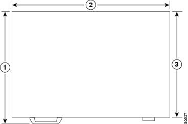
Figure 2-1 Cisco 7304 Chassis Measurements
Tools and Parts Required
Your Cisco 7304 chassis is fully assembled at the factory; no assembly is required. The chassis ships with the rack-mount brackets installed on the side of the chassis. However, you need the following tools and equipment to install the cable-management kit (if you are reinstalling the cable-management brackets), fan modules, and power supplies:
•
•
•
•
•
•
•
•
•
•
•
•
•
•
•
•
The cable-management kit includes the following parts:
•
•
•
–
–
–
–
–
In addition, you need the following external equipment:
•
•
•
Electrical Equipment Guidelines
The line cards and the carrier card with PCI port adapters are designed to be removed and replaced while the system is operating without presenting an electrical hazard or damage to the system.
Preventing Electrostatic Discharge Damage
Electrostatic discharge (ESD) damage, which occurs when electronic cards or components are improperly handled, can result in complete or intermittent system failures. Each line card consists of a printed circuit board that is fixed in a metal carrier. Electromagnetic interference (EMI) shielding, connectors, and a handle are integral components of the carrier. Although the carrier helps protect the boards, use an antistatic strap whenever handling the line card. Handle the carriers by the handle and the carrier edges only; never touch the boards or connector pins.
Site Requirement Guidelines
The environmental monitoring functionality in the Cisco 7304 router protects the system and components from potential damage from overvoltage and overtemperature conditions. To ensure normal operation and avoid unnecessary maintenance, plan your site configuration and prepare your site before installation. After installation, make sure the site maintains an ambient temperature of 32°F through 104°F (0°C through 40°C), and keep the area around the chassis as free from dust as is practical.
Planning a proper location for the Cisco 7304 router and the layout of your equipment rack or wiring closet is essential for successful system operation. Equipment placed too close together or inadequately ventilated can cause system overtemperature conditions. In addition, chassis panels made inaccessible by poor equipment placement can make system maintenance difficult. Following are precautions that can help avoid problems during installation and ongoing operation.
Warning
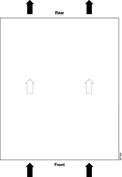
Figure 2-2 Airflow Through the Chassis
When you plan the location and layout of your equipment rack or wiring closet, you need to consider how air flows through your router. The Cisco 7304 router draws cooling air in through the intake vents on the front of the chassis and moves the air across the internal components and out the exhaust vents on the rear of the chassis. Figure 2-2 shows airflow through the chassis.
Temperature sensors on the system board monitor the internal air temperature and send warning messages when the internal air temperature approaches a specified threshold. If the internal temperature exceeds the specified threshold, the system environmental monitor shuts down all internal power to prevent equipment damage from excessive heat. (See the "Environmental Monitoring and Reporting Functions" section for temperature threshold information.)
Installing the Router
This section explains how to install a Cisco 7304 router in a general tabletop or workbench installation and in a rack, and how to attach I/O, line card, and power cables. The section contains the following topics:
•
•
•
•
General Tabletop or Workbench Installation
The router should already be in the area where you will install it, and your installation location should already be determined. If not, see the "Preparing to Install the Cisco 7304 Router" section, the "Site Requirement Guidelines" section, and the Site Preparation and Safety Guide.
When installing a Cisco 7304 router on a workbench or tabletop, ensure that the surface is clean and in a safe location and that you have considered the following:
•
•
•
•
•
•
•
Note
Following are the steps for installing a Cisco 7304 router on a workbench or tabletop:
Step 1
Step 2
Step 3
Step 4
Step 5
This completes the general tabletop or workbench installation.
Rack-Mounting a Cisco 7304 Router
The chassis mounts to two rack posts with brackets that attach to either the front or the rear of the sides of the chassis. The inside width between the two posts or mounting strips (left and right) must be at least 17.6 inches (44.7 cm).
Some equipment racks provide a power strip along the length of one of the mounting strips. Figure 2-7 shows a typical four-post equipment rack with a power strip along one of the back posts. If your rack has this feature, consider the position of the strip when planning fastener points to ensure that you will be able to pull the line card, a GBIC or SFP module, or CompactFlash Disk straight out of their respective slots.
We recommend that you allow at least 1 or 2 inches (2.54 or 5.08 cm) of vertical clearance between the router and any equipment directly above and below it.
Before beginning the installation, determine the type of rack you are using and whether or not you want the chassis front- or rear-mounted.
Attaching the Chassis Rack-Mount and Cable-Management Brackets
This section explains how to install the rack-mount and cable-management brackets at the front and the rear of a Cisco 7304 router. Before installing the chassis in the rack, you must install a rack-mount bracket on each side of the front or rear of the chassis.
The parts and tools required for installing the rack-mount brackets and cable-management brackets are listed in the "Tools and Parts Required" section.
Installing Rack-Mount Brackets on the Front of the Chassis
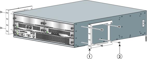
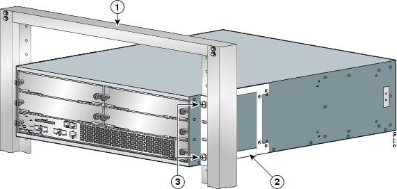
Figure 2-3 Attaching the Rack-Mount Brackets to the Front of the Router
Rack-mount bracket
Eight 8-18 x .37-inch screws—19-inch rack
Eight 8 x .755-inch screws—21-23-inch rack
Determine if you want the chassis to be flush-mounted or recessed. Figure 2-3 shows the brackets being attached for a front rack-mount. Depending on the bracket holes you use, the router will protrude or be recessed in the rack.
To install the rack-mount and cable-management brackets on a Cisco 7304 router for a front rack-mount configuration, complete the following steps:
Step 1
Step 2
Step 3
If you are attaching the cable-management brackets, continue to the next section. If not, go to the "Two-Post Rack Installation" section or the "Four-Post Rack Installation" section.
Attaching the Cable-Management Brackets
Figure 2-4 Installing the Cable-Management Brackets
Step 1
Step 2
Step 3
This completes the procedure for installing the cable-management brackets on a Cisco 7304 router for a front rack-mount configuration. Go to the "Installing the Chassis in the Rack" section.
Installing Rack-Mount Brackets on the Rear of the Chassis
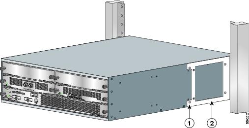
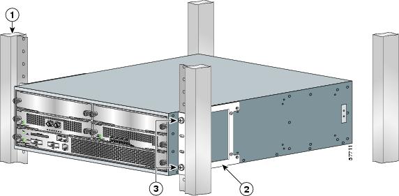
Figure 2-5 Attaching the Rack-Mount Brackets to the Rear of the Router
Eight 8-18 x .37-inch screws—19-inch rack
Eight 8 x .755-inch screws—21-23-inch rack
Rack-mount bracket
To install the rack-mount and cable-management brackets on a Cisco 7304 router for a rear rack-mount configuration, complete the following steps:
Step 1
Step 2
Step 3
Step 4
This completes the procedure for installing the rack-mount on a Cisco 7304 router for a rear rack-mount configuration. Go to the "Installing the Chassis in the Rack" section.
Installing the Chassis in the Rack
Caution
After installing the brackets on the chassis, you mount the router by securing the rack-mount brackets to two posts or mounting strips in the rack using the four screws provided. Because the brackets support the weight of the entire chassis, be sure to use all four screws to fasten the two rack-mount brackets to the rack posts. Figure 2-6 shows a typical installation in a two-post rack and Figure 2-7 shows a typical installation in a four-post rack.
We recommend that you allow at least 1 or 2 inches (2.54 or 5.08 cm) of vertical clearance between the router and any equipment directly above and below it.
To install the chassis in the rack, complete the following steps:
Step 1
Step 2
Step 3
Step 4
For two-post rack installation, go to the "Two-Post Rack Installation" section.
For four-post rack installation, go to the "Four-Post Rack Installation" section.
Two-Post Rack Installation
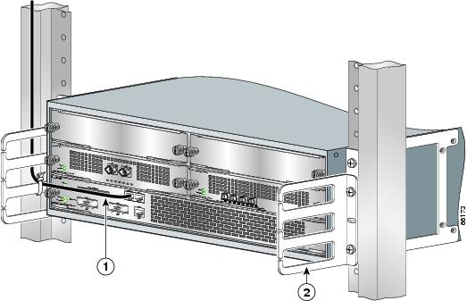
Figure 2-6 Two-Post Rack Installation
Step 1
Step 2
Step 3
Step 4
Step 5
Step 6
This completes the procedure for installing the chassis in the rack. Proceed to the "Attaching a Chassis Ground Connection" section to continue the installation.
Four-Post Rack Installation
Figure 2-7 Four-Post Rack Installation
Step 1
Step 2
Step 3
Step 4
Step 5
Step 6
This completes the procedure for installing the chassis in the rack. Proceed to the "Attaching a Chassis Ground Connection" section to continue the installation.
Attaching a Chassis Ground Connection
Before you connect power or turn on power to your router, we strongly recommend that you provide an adequate chassis ground (earth) connection for the router chassis. Chassis grounding connectors are provided on each Cisco 7304 router chassis.
To ensure the chassis grounding connection that you provide is adequate, you will need the following parts and tools:
•
•
•
•
•
•
Use the following procedure to attach the grounding lug to the chassis grounding connectors on your router chassis:
Step 1
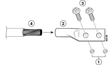
The chassis grounding connectors that provide a chassis ground connection for ESD equipment or a two-hole grounding lug are located on the side of the router, near the rear.
Warning
Figure 2-8 Attaching a Grounding Lug to the Chassis Grounding Connectors
Step 2
Step 3
Step 4
Step 5
Step 6
Step 7
Step 8
This completes the procedure for attaching a chassis ground connection. Go to the following cabling sections for information on attaching cables.
Connecting Line Card Cables
The instructions for connecting the cables for the line cards or PCI port adapters installed in the Cisco 7304 router are contained in the respective configuration notes for each line card and PCI port adapter.
Connecting I/O Cables
This section contains connection equipment and pinout information for the Fast Ethernet, Gigabit Ethernet, console, and auxiliary ports.
The NSE-100, NSE-150, and NPE-G100 are the three processing engines available for the Cisco 7304 router. Each processing engine has a different number of Gigabit Ethernet interfaces and different Gigabit Ethernet Gigabit Interface Converter port types (GBIC or SFP). In addition, the NSE-100 and NSE-150 each have a Fast Ethernet management port; the NSE-G100 does not. The console port and auxiliary port are the same on all three processors.
This section provides information about processing engine cables and ports and attaching the router to the network. Use the information about the NPE-G100, NSE-100, or the NSE-150, whichever is appropriate, for your installation.
Connecting Console and Auxiliary Port Cables
The Cisco 7304 router has a DCE-mode console port for connecting a console terminal, and a DTE-mode auxiliary port for connecting a modem or other DCE device (such as a CSU/DSU or other router) to your router.
Note
The Cisco 7304 router uses RJ-45 ports for both the auxiliary and console ports.
Before connecting a terminal to the console port, configure the terminal to match the router console port as follows: 9600 baud, 8 data bits, no parity, 2 stop bits (9600 8N2). After you establish normal router operation, you can disconnect the terminal.
For console and auxiliary port pinouts for the RJ-45 connector, see the "Console and Auxiliary Port Signals and Pinouts" section.
Figure 2-9 Console and Auxiliary Port RJ-45 Connections
Console port
Cable to console terminal or DTE
Auxiliary port
Cable to modem or DCE
RJ-45 connector
In the Cisco 7304 router, both the console and auxiliary ports use crossover or straight-through cables with RJ-45 connectors.
Adapters are available for connection to modems and other external communications equipment. (See Table 2-1.)
Table 2-1 Asynchronous Device Cabling Options
Crossover
RJ-45-to-DB-25M
Terminal or DTE
Crossover
RJ-45-to-DB-9M
Terminal or DTE
Straight-through
RJ-45-to-DB-25F
Modem or DCE
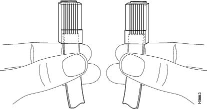
You can identify a rollover cable by comparing the two RJ-45 connectors at each end of the cable. When you hold the connectors side-by-side with the tab at the back, the wire connected to the pin on the outside of the left connector should be the same color as the pin on the outside of the right connector. A crossover cable reverses pins 1 and 8, 2 and 7, 3 and 6, and 4 and 5. (See Figure 2-10.)
Figure 2-10 Identifying a Crossover Cable
For console and auxiliary port pinouts, see "Specifications," the "Console and Auxiliary Port Signals and Pinouts" section.
Connecting Gigabit Ethernet Cables on the NSE-100
The NSE-100 has two Gigabit Ethernet (1000 Mbps) ports.
Note
NSE-100 Multimode and Single-Mode Optical Fiber Cables
For information on the GBICs that are supported on the NSE-100, see the "GBIC Ethernet GBIC Port and Cabling Specifications" section of the Cisco 7304 Network Services Engine Installation and Configuration Guide.
Connecting the GBIC Interface Cables on the NSE-100
The Gigabit Interface Converter (GBIC) port is a 1000-Mbps optical interface in the form of an SC-type duplex port that supports IEEE 802.3z interfaces compliant with the 1000BASEX standard.
After you install the GBIC in the Gigabit Ethernet port, you must attach the cables to the GBIC. The instructions that follow apply to all supported platforms.
See "Specifications," for more information on the Gigabit Ethernet port.
Note
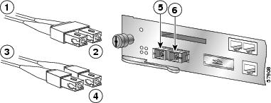
Figure 2-11 GBIC Port Connections on the NSE-100
To external 1000BASEX network
2 simplex connectors
1 duplex connector (TX and RX)
RX
To external 1000BASEX network
TX
Attach the appropriate optical fiber cable directly to the SC-type receptacle on the GBIC. You can use either simplex or duplex connectors for most devices. (Figure 2-11 shows a GBIC installed in GE slot 0.)
•
•
•
Caution
A mode-conditioning patch cord can be used with the GBIC-LX/LH to allow reliable laser transmission between the single-mode laser source on the GBIC and a multimode optical fiber cable. See the "Attaching the Mode-Conditioning Patch Cord for the NSE-100, NSE-150, or NPE-G100" section for installation instructions.
Connecting the Fast Ethernet 10/100 Cable to the Fast Ethernet Management Port on the NSE-100 and NSE-150
The NSE-100 and NSE-150 each have a Fast Ethernet management port; the NPE-G100 does not.
The Fast Ethernet port supports IEEE 802.3 (Ethernet), and IEEE 802.3u (Fast Ethernet) interfaces compliant with 10BASET and 100BASETX specifications.
The Fast Ethernet port supports standard straight-through and crossover Category 5 unshielded twisted-pair (UTP) cables with RJ-45 connectors. Cisco Systems does not supply Category 5 UTP cables; these cables are available commercially.
See "Specifications," for Fast Ethernet RJ-45 port specifications.
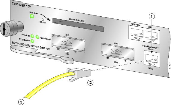
Figure 2-12 Attaching the Fast Ethernet Management Port 10/100 Cable (NSE-100 Example)
Attach a Fast Ethernet 10/100 cable to the Fast Ethernet management port.
Warning
Connecting Gigabit Ethernet Cables on the NPE-G100 and the NSE-150
The NPE-G100 has three Gigabit Ethernet (1000 Mbps) interfaces, and six ports; three SFP module ports and three RJ-45 ports. Any combination of three ports can be used at any one time.
The Gigabit Ethernet SFP port is a 1000-Mbps optical interface in the form of an LC-type duplex port that supports IEEE 802.3z interfaces compliant with the 1000BASEX standard.
Intra-Building Lightning Protection
Shielded cables, which are grounded at both ends, are required to be used on the 10/100/1000 Ethernet/Fast Ethernet /Gigabit Ethernet (RJ-45) port in order to be in compliance with requirement R4-11 in GR-1089-Core for a Central Office environment. This is not a requirement for customer premise installations.
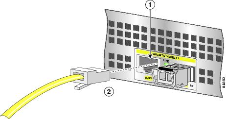
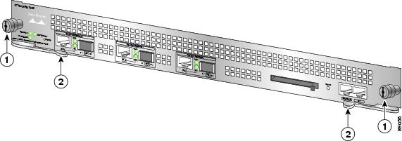
Figure 2-13 Attaching the RJ-45 Port Gigabit Ethernet Cables
Attach one, two, or three Gigabit Ethernet 10/100/1000 cables to the Gigabit Ethernet RJ-45 port 0, port 1, or port 2.
NPE-G100 Multimode and Single-Mode Optical Fiber Cables
For information on the SFPs that are supported on the NPE-G100, see the "SFP Port and Cabling Information" section of the Cisco 7304 Network Processing Engine Installation and Configuration Guide.
NSE-150 Multimode and Single-Mode Optical Fiber Cables
For information on the SFPs that are supported on the NSE-150, see the "SFP Port and Cabling Information" section of the Cisco 7304 Network Services Engine Installation and Configuration Guide.
About SFP Modules
Before powering up the router, install any Gigabit Ethernet SFP modules and cables.
The Gigabit Ethernet SFP port is a 1000-Mbps optical interface in the form of an LC-type duplex port that supports that supports IEEE 802.3z interfaces compliant with the 1000BASEX standard..
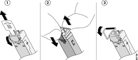
Figure 2-14 Types of SFP Module Latches
Note
•
•
•
•
•
•
Connecting the Gigabit Ethernet SFP Module and Cables
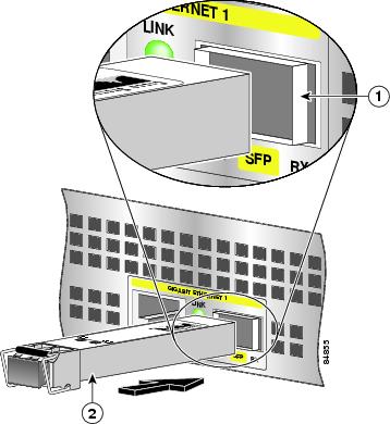
Figure 2-15 Inserting a Gigabit Ethernet SFP Module (NPE-G100 Example)
Use the following procedure to install an SFP module:
Step 1
Step 2
Note
Step 3
Step 4
Note
This completes the SFP module installation procedure.
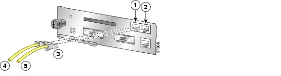
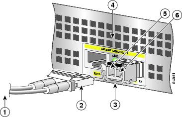
Figure 16 Inserting the Gigabit Ethernet Optical Fiber Cable in the SFP Module (NPE-G100 Example)
To external 1000BASEX network
Gigabit Ethernet SFP slot 1
Duplex connector (TX and RX)
TX (Gigabit Ethernet SFP slot 1)
Gigabit Ethernet SFP module
RX (Gigabit Ethernet SFP slot 1)
Step 1
Warning
Step 2
•
•
Caution
Attaching the Mode-Conditioning Patch Cord for the NSE-100, NSE-150, or NPE-G100
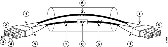
Figure 2-17 GBIC Mode-Conditioning Patch Cord
Beige color identifier
Multimode bar
To GE interface
Single-mode bar
RX
Offset
TX
To cable plant
Blue color identifier
To use the mode-conditioning patch cord, follow these steps:
Step 1
Step 2
Ensure that you connect the TX and RX ports on one end of the patch cord to the RX and TX ports (respectively) on the other end. Connect TX to RX and RX to TX.
Step 3
This completes the procedures for connecting the I/O cables.
Securing the Line Card and I/O Cables
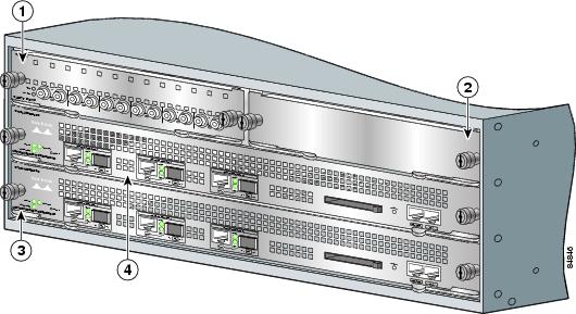
Figure 2-18 Securing Interface Cables Through the Cable-Management Brackets
If you have not already done so, run the line card or PCI port adapter interface cables and input/output cables through the cable-management brackets.
This completes the procedure for securing line card interface cables and input/output cables in the cable-management brackets. Proceed to the "Removing and Replacing a Power Supply" section for information on connecting power cables and powering on the router.
Removing and Replacing a Processing Engine
The Cisco 7304 router has three processing engine options: the NSE-100, the NSE-150, and the NPE-G100. You can install one or two processors in one chassis. If you install two processors in a single Cisco 7304 router, the two processors must be identical (either two NSE-100s, two NSE-150s, or two NPE-G100s).
For a complete description of the processing engines, functions, and features, see "Overview." For information on high availability, see the Cisco 7304 Network Processing Engine Installation and Configuration document.
Note
Removing a Processing Engine
To remove and replace the NSE-100, NSE-150, or NPE-G100, follow these steps:
Step 1
Step 2
Step 3
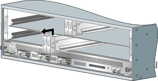
Figure 2-19 Cisco 7304 NPE-G100 Captive Installation Screws and Levers
Step 4
If the router is not installed in a standard 19-inch, four-post or two-post rack, skip to Step 8. If the router is installed in a rack, determine if any permanent rack fixtures, such as a power strip, are obstructing access to the front of the router. If a rack fixture is obstructing access to the router, proceed with Step 5.
Step 5
Step 6
Step 7
Note
Step 8
Caution
Step 9
This completes the procedure for removing an installed processing engine.
•
•
Removing the Slot Divider for a Redundant Configuration
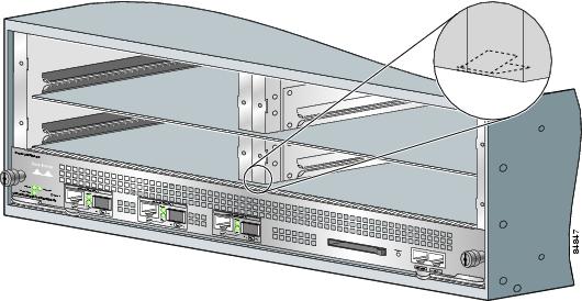
You must remove the slot divider in slot 2 in order to install a second processing engine in a Cisco 7304 router. See Figure 2-20.
Figure 2-20 Cisco 7304 Slot Designation
Figure 2-21 Slot Divider Retaining Mechanism
To remove the slot divider from the router, complete the following steps:
Step 1
Figure 2-22 Removing the Slot Divider
Step 2
This completes the procedure for removing a slot divider from a Cisco 7304 router.
To install the slot divider, slide the slot divider into the router until it clicks into the slot divider retaining mechanism.
Inserting a Processing Engine
The processing engine should be installed in slot 0. For high availability, install a second processing engine in slot 2.
Online insertion and removal (OIR) of the standby processing engine is supported. If two processing engines are installed, and one fails, whether primary or secondary, the failed processing engine can be removed without powering off the router, and a new processing engine installed.
Caution
To install a processing engine in the router, complete the following steps:
Step 1
Step 2
Step 3
Caution
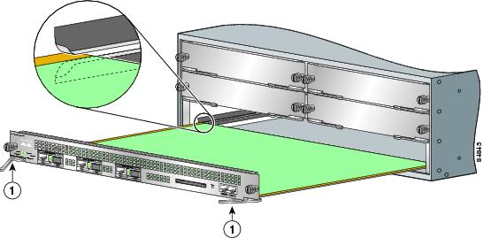
Figure 2-23 Aligning the NPE-G100 In the Slot Guides in a Cisco 7304 Router
Note
Step 4
Step 5
Step 6
Step 7
Note
Step 8
Step 9
Step 10
This completes the procedure for inserting the processing engine in a Cisco 7304 router.
For information on reconnecting the cables, see the "Connecting Gigabit Ethernet Cables on the NPE-G100 and the NSE-150" section and the "Connecting the Fast Ethernet 10/100 Cable to the Fast Ethernet Management Port on the NSE-100 and NSE-150" section.
For information on reconnecting input power and powering on the router, go to the "Reconnecting AC-Input Power and Powering Up the Router" section or the "Reconnecting DC-Input Power and Powering Up the Router" section.
For complete information about the NPE-G100, see the Cisco 7304 Network Processing Engine Installation and Configuration document. For complete information about the NSE-100 and NSE-150, see the Cisco 7304 Network Services Engine Installation and Configuration document.
Power Supply Overview
A Cisco 7304 router comes equipped with at least one AC-input or DC-input power supply that can supply 540W of power to the router. A Cisco 7304 router, however, can operate two power supplies in a single chassis. The additional power supplies can serve one of two functions: to supply additional power to the router that can be used for power load-sharing or to supply a hot-swappable, redundant power supply. The power supplied by the additional power supply helps ensure uptime; because the power load can be distributed between the power supplies in a dual power supply configuration, neither power supply operates near its maximum capacity and the possibility of power failure for the router is greatly reduced.
Redundant power is also useful as a failover; if a situation occurs where one power supply is down (for instance, a power supply fails or a new power supply needs to be installed), the router can continue to run properly using the other power supply.
Each power supply has fans that cool the power supply and the internal components of the router. These fans need to be operating on both sides of the router to properly cool the router's internal components, and a dual power supply configuration provides these fans on each side of the router. In single power supply configurations, however, a fan module is required in the chassis without the second power supply to ensure the router's internal components remain at a proper working temperature. Filler plates are not available and should not be used for Cisco 7304 routers.
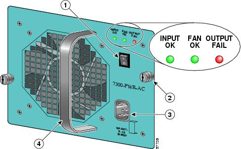
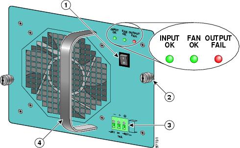
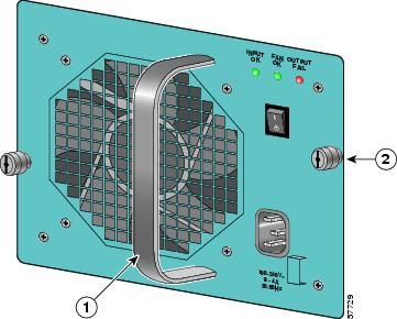
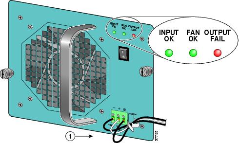
The faceplates of both power supplies have a green INPUT OK LED, a green FAN OK LED, a red OUTPUT FAIL LED, a handle, an on/standby switch, and two captive installation screws (refer to Figure 2-24 and Figure 2-25). An AC-input power receptacle is available on the AC-input power supply and a DC-input terminal block is available on the DC-input power supply.
A single power supply (in a single power supply configuration) can supply up to 540W output voltage (+12 VDC at 44.6A and +3.3 VDC at 1.5A) to the router's internal components through the router midplane. A dual power supply configuration can provide up to 970W output power.
Warning
Figure 2-24 Cisco 7304 AC-Input Power Supply Faceplate
Figure 2-25 Cisco 7304 DC-Input Power Supply Faceplate
LEDs
LEDs are used to monitor the input power sources, the power supply's outputs, and fan status. Both AC-input and DC-input power supplies have a green INPUT OK LED, a green FAN OK LED, and a red OUTPUT FAIL LED.
The INPUT OK LED is used to monitor the status of the input voltage. If the AC input voltage is greater than 85 VAC on an AC-input power supply, then the green INPUT OK LED is illuminated. If the AC input voltage is between 70VAC and 85 VAC, then the green INPUT OK LED can be on, off, or blinking. If the input voltage is less than 70 VAC, the INPUT OK LED will not illuminate.
On a DC-input power supply, the INPUT OK LED is illuminated when the DC input voltage is greater than -38 VDC. If the DC input voltage is between -33.0 VDC to -38 VDC, the INPUT OK LED can be on, off, or blinking. If the DC input voltage is less than -33 VDC, the INPUT OK LED will not illuminate.
On both the AC-input and DC-input power supplies, the FAN OK LED is used to monitor the status of the power supply fans. When the fans operate properly, the FAN OK LED is illuminated. If the green FAN OK LED is not illuminated, at least one fan in the power supply is operating at less than 60% of its desired performance.
Note
The OUTPUT FAIL LED is used to monitor the power supply DC output voltages used to power the router. The normal operating ranges for the 12 VDC output voltage is between 10V and 13.8V. If the output voltages are within normal operating ranges, the red OUTPUT FAIL LED is not illuminated. If the 12 VDC output voltages are above (more than 13.8V) or below (less than 10V) normal ranges, the red OUTPUT FAIL LED is illuminated.
Use the following tables for LED status information.
Power Supply Specifications
The following table lists the AC-input and DC-input power supply specifications for the Cisco 7304 router:
Table 2-6 Cisco 7304 Power Supply Specifications
AC-input power
800 VA maximum (single supply configuration)
AC-input voltage rating
100-240 VAC1 wide input with power factor correction
AC-input current rating
Rated for 8A when Vin = 100 VAC or 4A when Vin = 200 VAC
AC-input frequency rating
50-60 Hz2
AC-input cable
18 AWG3 three-wire cable, with a three-lead IEC-320 receptacle on the power supply end, and a country-dependent plug on the power source end
DC-input power
750 VA maximum configuration
DC-input voltage ratings
-48 VDC4 nominal, maximum range -48 VDC to -60 VDC (-40.5 to
-72 VDC supply tolerance)DC-input current ratings
16A at -48 VDC (18.5A at -40.5 VDC, 10.4A at -72 VDC supply tolerance)
DC-input cable
12 AWG only
1 VAC = volts alternating current
2 Hz = hertz
3 AWG = American Wire Gauge
4 VDC = volts direct current
Note
Note
Removing and Replacing a Power Supply
The procedures for removing and replacing the AC-input or DC-input power supply are explained in the following sections:
•
•
•
Note
Powering Down the Router and Disconnecting Input Power
The following sections describe how to remove power from an AC-input power supply and a DC-input power supply:
•
•
Powering Down an AC-Input Power Supply
To power down the AC-input power supply to the Cisco 7304 router, complete the following steps:
Note
Step 1
Note
Step 2
•
•
•
Step 3
Note
This completes the procedure for powering down an AC-input power supply on a Cisco 7304 router.
If you are removing an AC-input power supply, proceed to the "Removing the Power Supply" section.
Powering Down a DC-Input Power Supply and Removing the DC-Input Leads
Warning
Note that the power to the power supply should be off, not necessarily all power to the router. A DC-Input power supply can be running when another power supply or fan module is being removed or replaced.
Warning
Warning
Note
To power down the DC-input power supply to the Cisco 7304 router and remove the DC-input power leads from the DC-input power supply, complete the following steps:
Step 1
Note
Step 2
Step 3
Step 4
Note
This completes the procedure for disconnecting DC-input power and removing the DC-input power leads from the DC-input power supply. Proceed to the ""Removing the Power Supply" section.
Removing the Power Supply
To remove the AC-input or DC-input power supply from the Cisco 7304 router, complete the following steps:
Step 1
If the router is not installed in a standard four-post or 2-post rack, skip to Step 5. If the router is installed in a rack, determine if any permanent rack fixtures, such as a power strip, are obstructing access to the power supply. If a rack fixture is obstructing access to the power supply, proceed to Step 2.
Figure 2-26 Captive Installation Screws and Handle on the Power Supply
Step 2
Step 3
Step 4
Caution
This completes the procedure for removing the power supply from a Cisco 7304 router.
Replacing the Power Supply
Caution
To install a new power supply into a Cisco 7304 chassis, complete the following steps:
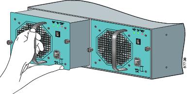
Step 1
Figure 2-27 Holding the Power Supply
Step 2
Step 3
Caution
Step 4
Note
Step 5
Step 6
Caution
There are no filler plates available for Cisco 7304 routers.
This completes the procedures for replacing a power supply in a Cisco 7304 router.
Reconnecting AC-Input Power and Powering Up the Router
The following procedures explain how to reconnect AC-input power to a Cisco 7304 router, power up the router, and verify a successful system boot.
If you are reconnecting DC-input power, proceed to the "Reconnecting DC-Input Power and Powering Up the Router" section.
Warning
To reconnect AC-input power to the Cisco 7304 router, complete the following steps:
Step 1
•
•
•
•
•
Step 2
Note
Step 3
Step 4
Step 5
Note
Step 6
Step 7
If another power source was not running before installing the AC-input power source, observe the router's initialization process. When the system boot is complete (a few seconds), the processing engine begins to initialize the line cards. During this initialization, the LEDs on each line card behave differently (most flash on and off). The STATUS LED on each line card goes on when initialization is completed, and the console screen displays a script and system banner.When another power source was already configured, ensure that the new AC-input power source is operating effectively by checking the INPUT OK LED and the FAN OK LED on the power supply and ensuring that the power supply is properly aligned and the captive installation screws are tightened. The INPUT OK LED and FAN OK LED should illuminate shortly after the power supply is connected.
Note
This completes the steps for reconnecting the AC-input power supply to a Cisco 7304 router.
Reconnecting DC-Input Power and Powering Up the Router
The following procedures explain how to reconnect DC-input power to a Cisco 7304 router, power up the router, and verify a successful system boot.
Warning
Note
Warning
Note that the power to the power supply should be off, not necessarily all power to the router. A DC-Input power supply can be running when another power supply or fan module is being removed or replaced.
Warning
Warning
To reconnect DC-input power to the Cisco 7304 router, complete the following steps:
Step 1
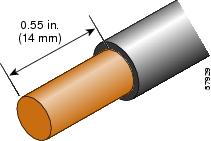
Step 2
Figure 2-28 Stripping the DC-Input Leads
Step 3
Note
Caution
Figure 2-29 Connecting DC-Input Power
Step 4
Note
Step 5
Note
Step 6
Note
Step 7
Step 8
If another power source was not running before installing the DC-input power source, observe the router's initialization process. When the system boot is complete (a few seconds), the processing engine begins to initialize the line cards. During this initialization, the LEDs on each line card behave differently (most flash on and off). The STATUS LED on each line card goes on when initialization is completed, and the console screen displays a script and system banner.When another power source was already configured, ensure that the new DC-input power source is operating effectively by checking the INPUT OK LED and the FAN OK LED on the power supply and ensuring that the power supply is properly aligned and the captive installation screws are tightened. The INPUT OK LED and FAN OK LED should illuminate shortly after the power supply is connected.
Note
This completes the steps for reconnecting DC-input power to a Cisco 7304 router.
Fan Module Overview
The fan module on a Cisco 7304 router contains two internal fans. The fan module is powered by the + 12V DC-input power from the 540W single power supply, which provides power to the internal components of the Cisco 7304 router. The purpose of the fan module is to cool the interior components of the router.
A Cisco 7304 router can be ordered with a fan module and at least one AC-input or DC-input power supply. The Cisco 7304 router requires fans in both sides of the chassis to cool all of the router's internal components, and the fan module is used to cool the router components on the side opposite of the power supply. If two power supplies are configured in the Cisco 7304 router, the fans in the power supplies provide sufficient cooling for the router's internal components, making the fan module unnecessary.
A fan module is required if a Cisco 7304 router is running from a single power supply. Filler plates are not available for Cisco 7304 routers and should not be used.
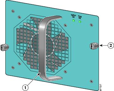
Figure 2-30 Cisco 7304 Fan Module
LEDs
The INPUT OK LED monitors the input voltage used to power the fan. Under normal system operation, the power supply supplies +12V to the router's internal components, including the fan module, and the INPUT OK LED on the fan module is illuminated. If the router's internal components are receiving +9.6V or less, the INPUT OK LED will not illuminate. The INPUT OK LED will blink if the router's internal components are receiving between +9.6V and +10.8V.
The green FAN OK LED is used to monitor fan effectiveness. The green FAN OK LED should be illuminated when the fan module is functioning properly and off when a fan failure occurs. A fan failure occurs when the actual speed of one or both fans is less than 60% of its maximum performance level. When a fan failure occurs, the environment monitor will send an error message to the router console indicating which fan is not functioning properly. An SNMP trap indicating that the fan is not functioning properly is also sent. A fan failure is often audible and can be verified by visually checking that the fan is not rotating or is rotating slowly.
Removing and Replacing the Fan Module
The following sections explains how to remove and replace a fan module in a Cisco 7304 router:
Removing the Fan Module
To remove the fan module from a Cisco 7304 router, complete the following steps:
Note
Step 1
If the router is not installed in a standard four-post or 2-post rack, skip to Step 5. If the router is installed in a rack, determine if any permanent rack fixtures, such as a power strip, are obstructing access to the fan module. If a rack fixture is obstructing access to the fan module, proceed to Step 2.
Step 2
Step 3
Step 4
Step 5
This completes the procedure for removing the fan module from a Cisco 7304 router.
Replacing the Fan Module
To replace a fan module in a Cisco 7304 router, complete the following steps:
Step 1
Step 2
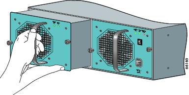
Figure 2-31 Holding the Fan Module
Step 3
Caution
Step 4
Note
Step 5
Step 6
This completes the procedures for replacing a fan module in the router.