- Preface
- NPE-100, NPE-150, and NPE-200 Overview
- NPE-175 and NPE-225 Overview
- NPE-300 and NPE-400 Overview
- NSE-1 Overview
- NPE-G1 Overview
- NPE-G2 Overview
- NPE-G1 and NPE-G2 Installation and Configuration Information
- Preparation for Installation
- Removing and Installing the NPE or NSE
- Configuration Tasks and Troubleshooting Information
Network Processing Engine and Network Services Engine Installation and Configuration
Bias-Free Language
The documentation set for this product strives to use bias-free language. For the purposes of this documentation set, bias-free is defined as language that does not imply discrimination based on age, disability, gender, racial identity, ethnic identity, sexual orientation, socioeconomic status, and intersectionality. Exceptions may be present in the documentation due to language that is hardcoded in the user interfaces of the product software, language used based on RFP documentation, or language that is used by a referenced third-party product. Learn more about how Cisco is using Inclusive Language.
- Updated:
- November 30, 2006
Chapter: Configuration Tasks and Troubleshooting Information
- NPE Configuration Tasks
- NSE Configuration Tasks
- Boot Changes in Cisco IOS Release 12.2
- Troubleshooting the NPE-G1 or NPE-G2
- .Troubleshooting the NPE-100 Through NPE-400
- NPE or NSE show Commands
Configuration Tasks and Troubleshooting Information
This chapter provides configuration and troubleshooting information. Troubleshooting information includes general show commands, show commands specific to the NSE-1, and error messages and the like. Instructions for removing a power supply for easier removal or installation of the network services engine are also provided. The following topics are covered in this chapter:
•![]() Boot Changes in Cisco IOS Release 12.2
Boot Changes in Cisco IOS Release 12.2
•![]() Troubleshooting the NPE-G1 or NPE-G2
Troubleshooting the NPE-G1 or NPE-G2
•![]() .Troubleshooting the NPE-100 Through NPE-400
.Troubleshooting the NPE-100 Through NPE-400
•![]() Using Debugging Commands and PXF
Using Debugging Commands and PXF
•![]() PXF Troubleshooting Information
PXF Troubleshooting Information
•![]() Removing and Replacing an AC-Input or DC-Input Power Supply
Removing and Replacing an AC-Input or DC-Input Power Supply
•![]() Fiber Optic Cleaning Information
Fiber Optic Cleaning Information
NPE Configuration Tasks
Network processing engines (NPEs) NPE-100 through NPE-400 are not configurable. There are no tasks to perform.
For NPE-G1and NPE-G2 configuration tasks, see Chapter 7, "NPE-G1 and NPE-G2 Installation and Configuration Information."
NSE Configuration Tasks
The PXF processor is turned on by default. If it is ever disabled, you must enable it to take advantage of IP packet switching and feature acceleration.

Note ![]() Before enabling the PXF processor, you must have IP routing and IP CEF switching turned on.
Before enabling the PXF processor, you must have IP routing and IP CEF switching turned on.
To manually disable or enable the PXF processor, use the ip pxf global command. To see a current list of Cisco IOS features supported by the PXF processor, go to Cisco.com and search for Cisco 7200 product literature for the NSE-1.
Boot Changes in Cisco IOS Release 12.2
Cisco IOS Release 12.2 changed the behavior of the ROM monitor (ROMmon) during the bootup sequence. Previously, users could issue the break signal during the bootup sequence to break into ROMmon, and then immediately boot a new Cisco IOS image using the boot command.
This behavior is no longer allowed when the router is using a boot image that is based on Cisco IOS Release 12.2, because interrupting the boot process could leave the hardware and software registers in an unknown state. Instead, use the following procedure when using a router with a Cisco IOS Release 12.2 boot image:
Step 1 ![]() At the router console prompt, send a BREAK signal to interrupt the boot process and enter ROMmon.
At the router console prompt, send a BREAK signal to interrupt the boot process and enter ROMmon.
Step 2 ![]() Set the configure register to boot into ROMmon by using the confreg 0x0 command.
Set the configure register to boot into ROMmon by using the confreg 0x0 command.
Step 3 ![]() Use the reset command to reset the NPE and boot into ROMmon. This ensures a clean boot into ROMmon, with all registers set to a known state.
Use the reset command to reset the NPE and boot into ROMmon. This ensures a clean boot into ROMmon, with all registers set to a known state.
Step 4 ![]() Set the configuration register to boot a Cisco IOS image by using the confreg 0x2102 command.
Set the configuration register to boot a Cisco IOS image by using the confreg 0x2102 command.
Step 5 ![]() Use the boot command to boot the desired Cisco IOS image.
Use the boot command to boot the desired Cisco IOS image.
Troubleshooting the NPE-G1 or NPE-G2
The procedures in this section assume that the NPE-G1, NPE-G2, Cisco uBR7200-NPE-G1, or Cisco uBR7200-NPE-G2 is installed without an I/O controller. Unless otherwise indicated, all references to NPE-G1 refer to both the NPE-G1 and Cisco uBR7200-NPE-G1. Also, unless otherwise indicated, all references to NPE-G2 refer to both the NPE-G2 and Cisco uBR7200-NPE-G2.
Note ![]() The NPE-G2 has its own Cisco IOS software image with the prefix "c7200p-" in the software images filenames, including the boot image. The NPE-G2 does not boot up with a software image with the prefix "c7200-". Previous network processing engines, or the network services engine, do not boot up with the "c7200p-" boot image. They use the prefix "c7200-".
The NPE-G2 has its own Cisco IOS software image with the prefix "c7200p-" in the software images filenames, including the boot image. The NPE-G2 does not boot up with a software image with the prefix "c7200-". Previous network processing engines, or the network services engine, do not boot up with the "c7200p-" boot image. They use the prefix "c7200-".
Note ![]() The Cisco uBR7200-NPE-G2 has its own Cisco IOS software image with the prefix "ubr7200p".
The Cisco uBR7200-NPE-G2 has its own Cisco IOS software image with the prefix "ubr7200p".
For NPE-G1 or NPE-G2 ROMmon upgrade error messages, see the "ROMmon Upgrade Error Messages" section on page 7-66.

Note ![]() If an I/O controller is installed with the NPE-G1 or NPE-G2, only the EN (Enable) LED and LINK LED information in this section is applicable.
If an I/O controller is installed with the NPE-G1 or NPE-G2, only the EN (Enable) LED and LINK LED information in this section is applicable.
The procedures in this section assume that the NPE-G1 or NPE-G2 and the router itself are in the original factory configuration, and that you have not made changes to your configuration file.
•![]() If the NPE-G1 POWER ON LED or the NPE-G2 PWR OK LED does not go on as expected, make sure the power to the router is turned off, reseat the NPE-G1or NPE-G2 in its slot, and restart the router.
If the NPE-G1 POWER ON LED or the NPE-G2 PWR OK LED does not go on as expected, make sure the power to the router is turned off, reseat the NPE-G1or NPE-G2 in its slot, and restart the router.
If the POWER ON LED or the PWR OK LED remains off, the system detected a processor hardware failure. (This LED should be on in normal operation.) Contact a service representative for instructions.
•![]() If the EN (Enable) LED does not come on when a Gigabit Ethernet RJ-45 port is selected, try using a different cable. If the EN (Enable) LED does not come on, check to be sure that in software the RJ-45 media is selected. See the "Changing the Media Type of the Native Gigabit Ethernet GBIC, SFP, or RJ-45 Ports" section on page 7-56.
If the EN (Enable) LED does not come on when a Gigabit Ethernet RJ-45 port is selected, try using a different cable. If the EN (Enable) LED does not come on, check to be sure that in software the RJ-45 media is selected. See the "Changing the Media Type of the Native Gigabit Ethernet GBIC, SFP, or RJ-45 Ports" section on page 7-56.
•![]() If the EN LED remains off when the GBIC media or SFP media are selected, the LED is functioning properly. If the GBIC port or SFP port does not seem to be operating, try installing a different GBIC or a different SFP module, or a different cable. Also check in software to be sure the optical fiber media is selected. See the "Changing the Media Type of the Native Gigabit Ethernet GBIC, SFP, or RJ-45 Ports" section on page 7-56.
If the EN LED remains off when the GBIC media or SFP media are selected, the LED is functioning properly. If the GBIC port or SFP port does not seem to be operating, try installing a different GBIC or a different SFP module, or a different cable. Also check in software to be sure the optical fiber media is selected. See the "Changing the Media Type of the Native Gigabit Ethernet GBIC, SFP, or RJ-45 Ports" section on page 7-56.
If any of these actions do not produce a functioning LED, contact an authorized service representative.
•![]() If the LINK LED does not come on only when any of the Gigabit Ethernet media are in use:
If the LINK LED does not come on only when any of the Gigabit Ethernet media are in use:
–![]() Check that the router is receiving power.
Check that the router is receiving power.
–![]() Check that the correct media type is selected in software. See the "Configuring the Native Gigabit Ethernet Interfaces" section on page 7-56.
Check that the correct media type is selected in software. See the "Configuring the Native Gigabit Ethernet Interfaces" section on page 7-56.
–![]() Check that the media cables are functioning and are completely connected to the NPE-G1 or NPE-G2.
Check that the media cables are functioning and are completely connected to the NPE-G1 or NPE-G2.
–![]() If the GBIC modules are being used, check to be sure they are connected to the NPE-G1. If SFP modules are being used, check to be sure they are connected to the NPE-G2.
If the GBIC modules are being used, check to be sure they are connected to the NPE-G1. If SFP modules are being used, check to be sure they are connected to the NPE-G2.
If any of these actions do not produce a functioning LED, contact an authorized service representative.
•![]() If the SLOT ACTIVE LED on the NPE-G1, or the CF ACTV LED on the NPE-G2 does not comes on when the CompactFlash Disk slot is being used, try inserting a different CompactFlash Disk. If the SLOT ACTIVE LED on the NPE-G1 or the CF ACTV LED on the NPE-G2 still does not come on, contact an authorized service representative.
If the SLOT ACTIVE LED on the NPE-G1, or the CF ACTV LED on the NPE-G2 does not comes on when the CompactFlash Disk slot is being used, try inserting a different CompactFlash Disk. If the SLOT ACTIVE LED on the NPE-G1 or the CF ACTV LED on the NPE-G2 still does not come on, contact an authorized service representative.
•![]() Check the Cisco IOS release running on the router. For minimum software release information, see the "Software Requirements" section on page 8-4
Check the Cisco IOS release running on the router. For minimum software release information, see the "Software Requirements" section on page 8-4
.Troubleshooting the NPE-100 Through NPE-400
The procedures in this section assume that the I/O controller, network processing engine or network services engine, and the router itself are in the original factory configuration, and that you have not made any changes to your configuration file.
If the I/O controller ENABLED LED does not go on as expected, make sure the power to the router is turned off, reseat the network processing engine or network services engine in its slot, and restart the router.
If the ENABLED LED remains off, the system detected a processor hardware failure. (This LED should be on in normal operation.) Contact a service representative for instructions.
Check the Cisco IOS release running on the router. For minimum software release information, see the "Software Requirements" section on page 8-4.
NPE or NSE show Commands
Use the global show version or show c7200 commands to obtain information about the NPE or NSE, hardware, and software installed on your router. Examples of each follow.
Using the show version Command
Use the show version command to display the configuration of the system hardware including the NPE or NSE and the software version.
The following example of the show version command identifies an NPE-400 installed in a Cisco 7206VXR router:
Router# show version
Cisco Internetwork Operating System Software
IOS (tm) 7200 Software (C7200-P-M), Released Version 12.1(20000622:181759)
Copyright (c) 1986-2000 by cisco Systems, Inc.
Compiled Thu 22-Jun-00 11:18 by BIFF
Image text-base:0x60008950, data-base:0x60BD8000
(display text omitted)
cisco 7206VXR (NPE400) processor (revision 0xFF) with 114688K/16384K bytes
of memory.
Processor board ID 8771013
R7000 CPU at 350Mhz, Implementation 39, Rev 2.1, 256KB L2, 4096KB L3 Cache
6 slot VXR midplane, Version 2.1
(display text omitted)
The following example shows an NSE-1 installed in a Cisco 7206VXR router:
Router# show version
Cisco Internetwork Operating System Software
IOS (tm) 7200 Software (C7200-JS-M), Version 12.1(1)E
Copyright (c) 1986-2000 by cisco Systems, Inc.
Compiled Wed 22-Mar-00 08:37 by Biff
Image text-base:0x60008900, data-base:0x6141C000
(display text omitted)
cisco 7206VXR (NSE-1) processor (revision B) with 57344K/8192K bytes of memory.
R7000 CPU at 262Mhz, Implementation 39, Rev 1.0, 256KB L2 Cache6 slot VXR midplane,
Version 2.0
(display text omitted)
PXF processor tmc is running.
6 FastEthernet/IEEE 802.3 interface(s)
10 Serial network interface(s)
2 HSSI network interface(s)
2 Channelized T3 port(s)
125K bytes of non-volatile configuration memory.
(display text omitted)
Using the show c7200 Command
Use the show c7200 command to obtain information about the router.
Router# show c7200
Network IO Interrupt Throttling:
throttle count=0, timer count=0
active=0, configured=0
netint usec=4000, netint mask usec=200
C7200 Midplane EEPROM:
Hardware revision 2.0 Board revision A0
Serial number 16061833 Part number 73-3223-05
Test history 0x0 RMA number 00-00-00
MAC=00b0.4aae.4000, MAC Size=1024
EEPROM format version 1, Model=0x6
EEPROM contents (hex):
0x20:01 06 02 00 00 F5 15 89 49 0C 97 05 00 B0 4A AE
0x30:40 00 04 00 00 00 00 00 00 01 13 50 00 00 FF 00
C7206VXR CPU EEPROM:
Hardware revision 1.2 Board revision A0
Serial number 15053437 Part number 73-3453-04
Test history 0x0 RMA number 00-00-00
EEPROM format version 1
EEPROM contents (hex):
0x20:01 C2 01 02 00 E5 B2 7D 49 0D 7D 04 00 00 00 00
0x30:50 00 00 00 00 01 14 00 00 00 FF FF FF FF FF FF
C7200 PE EEPROM:
Hardware Revision :1.0
Top Assy. Part Number :800-05272-04
Part Number :73-4068-02
Board Revision :A0
PCB Serial Number :12342775
RMA History :00
Fab Version :02
Fab Part Number :28-3146-02
Product Number :NSE1
EEPROM format version 4
EEPROM contents (hex):
0x00:04 FF 40 00 DE 41 01 00 C0 46 03 20 00 14 98 04
0x10:82 49 0F E4 02 42 41 30 C1 8B 31 32 33 34 32 37
0x20:37 35 20 20 20 04 00 02 02 85 1C 0C 4A 02 CB 84
0x30:4E 53 45 31 FF FF FF FF FF FF FF FF FF FF FF FF
0x40:FF FF FF FF FF FF FF FF FF FF FF FF FF FF FF FF
0x50:FF FF FF FF FF FF FF FF FF FF FF FF FF FF FF FF
0x60:FF FF FF FF FF FF FF FF FF FF FF FF FF FF FF FF
0x70:FF FF FF FF FF FF FF FF FF FF FF FF FF FF FF FF
Using the show environment Command with the NPE-G2—NPE-G2 -Specific Output
The output for the show environment command has changed slightly for the NPE-G2. See the NPE-G2 Support for the show environment Command document for information about changes to the output of the show environment command with the NPE-G2 at: http://www.cisco.com/en/US/docs/ios/12_4/12_4x/12_4_4xd/showenv2.html.
NSE-1 show Commands
Following are five NSE-1-specific show pxf commands and several subcommands. Included in this section are examples for each command.
•![]() show pxf accounting ?
show pxf accounting ?
–![]() show pxf accounting summary
show pxf accounting summary
–![]() show pxf accounting interface
show pxf accounting interface
•![]() show pxf crash
show pxf crash
•![]() show pxf info
show pxf info
•![]() show pxf interface
show pxf interface
•![]() show pxf feature ?
show pxf feature ?
Sample output for these commands and subcommands follows.
Using the show pxf accounting ? Command and Subcommands
The following is an example of the show pxf accounting ? command with sample output:
Router# show pxf accounting ?
ATM ATM interface
Ethernet IEEE 802.3
FastEthernet FastEthernet IEEE 802.3
Hssi High Speed Serial Interface
Null Null interface
POS Packet over Sonet
Serial Serial
summary PXF summary statistics
The following is an example of the show pxf accounting summary command with sample output:
Router# show pxf accounting summary
Pkts Dropped RP Processed Ignored
Total 0 90 0
PXF complex busy : 8%
PXF input pipeline full: 0%
PXF Statistic:
Packets RP -> PXF:
switch ip: 0
switch raw: 90
qos fastsend: 0
qos enqueue: 0
Total: 90
Packets PXF -> RP:
qos pkts: 0
fast pkts: 0
drops:total 0
punts:total 90
" not IP : 89
" CEF receive : 1
Total: 90
Packets ignored: 0 | ring space:
shadow ring full: 0 | shadow ring: 16382
in ring full: 0 | inring: 995
PXF inactive: 0
tx credits: 0 | delayed credits: 0
holdq enqueues: 0 | requeue drops: 0
interrupts: 90 | pending read bytes: 0
L2TP tunnel read: 0 | session stats: 0
Interface Pkts In Chars In Pkts Out Chars Out Punted Dropped
Et0/0 0 0 0 0 93 0
Gi0/0 0 0 0 0 0 0
Fa1/0 0 0 0 0 0 0
Fa4/0 0 0 0 0 0 0
Vt1 0 0 0 0 0 0
Lo0 0 0 0 0 0 0
The following is an example of the show pxf accounting interface command with sample output:
Router# show pxf accounting POS4/0
Interface Pkts In Chars In Pkts Out Chars Out Punted
POS4/0 19 1064 0 0 44
Using the show pxf crash Command
The following is an example of the show pxf crash command with sample output:
Router# show pxf crash
toaster-uut#sh pxf crash
EX_Type = 0x80000000
EX_ID(b0~3,16~17) = 0x00400
CPU_EX_ID(b0~15) = 0x0004
IHB_EX_Type(b0~5) = 0x00
XRAM0(b0~13) = 0x00000
XRAM1(b0~13) = 0x00000
XRAM2(b0~13) = 0x00000
XRAM3(b0~13) = 0x00000
Pipeline:7FDEFD pdone[3210]:1F 17 17 1D
ICM0(b4~13) = 0x00000 ICM1(b4~13) = 0x00000
ICM2(b4~13) = 0x00010 ICM3(b4~13) = 0x00000
LOCK0(b0~4) = 0x00000 LOCK1(b0~4) = 0x00000
LOCK2(b0~4) = 0x00000 LOCK3(b0~4) = 0x00000
CPU0/2: SW EX Type=0x00000000 LBUS EX Type=0x00000081 HW EX
Type=0x00000400
CPU:row=0x0 column=0x2 cpu=0x2
PC:0000098E LR:0000087F CR:002C4C00
r0:00000000 r1:8001CEA0 r2:80784390 r3:00000000
r4:00005400 r5:80D3BA04 r6:80A7CA00 r7:00000004
r8:00000000 r9:00000008 r10:80092324 r11:800A6200
r12:00000033 r13:00000008 r14:00000000 r15:00000000
misr1a:00000000 misr1bhi:00000000 misr1blo:00000000 misr2hi:00000000
misr2lo:00000000 reserve:00000000 reserve:00000000 reserve:00000000
sisr1a:01000040 sisr1b:00000000 irhi:4402200F irlo:00000000
cAll:C20DE822 DCD1:00020400 DCD2:00000002 CNTL:00000000
TBuf intr 0:1111111F
TBuf intr 1:020FFFF0
TBuf intr 2:00003C80
TBuf intr 3:80000000
TBuf intr 4:00000400
Xram return:00000000
Icram return hi:80024E00
Icram return lo:800A4E00
TBuf addr 0:005E6800 TBuf sblock1 0:8078A374 TBuf sblock0 0:804FD600
TBuf addr 1:005E6800 TBuf sblock1 1:8078A374 TBuf sblock0 1:804FD600
TBuf addr 2:005E6800 TBuf sblock1 2:8078A374 TBuf sblock0 2:804FD600
TBuf addr 3:005E6800 TBuf sblock1 3:8078A374 TBuf sblock0 3:804FD600
TBuf addr 4:005E6800 TBuf sblock1 4:8078A374 TBuf sblock0 4:804FD600
TBuf addr 5:005E6800 TBuf sblock1 5:8078A374 TBuf sblock0 5:804FD600
TBuf addr 6:005E6800 TBuf sblock1 6:8078A374 TBuf sblock0 6:804FD600
TBuf addr 7:005E6800 TBuf sblock1 7:8078A374 TBuf sblock0 7:804FD600
Using the show pxf info Command
The following is an example of the show pxf info command with sample output:
Router# show pxf info
pxf:tmc type TMC ASIC Pass1 (no ECC) revision 3
ucode:filename 'system:pxf/ucode0' revision 1.1
state: is running, number of starts 1
uptime:15:24:18
Memory Configuration:
Bank Name Total Reserved In-use Free
tmc internal memory column 0 16 Kb 10 Kb 0 bytes 6144 bytes
tmc column 0 memory bank 0 32 Mb 26 Mb 16 Kb 5554 Kb
tmc internal memory column 1 16 Kb 512 bytes 0 bytes 15 Kb
tmc column 1 memory bank 0 32 Mb 669 Kb 2015 Kb 29 Mb
tmc internal memory column 2 16 Kb 6656 bytes 0 bytes 9728 bytes
tmc column 2 memory bank 0 32 Mb 441 Kb 800 Kb 30 Mb
tmc internal memory column 3 16 Kb 15 Kb 0 bytes 512 bytes
tmc column 3 memory bank 0 32 Mb 2092 Kb 128 Kb 29 Mb
Using the show pxf interface Command
The show pxf interface command provides a summary of the interfaces in the router and which PXF features or capabilities are enabled on these interfaces. The following is an example of the show pxf interface command:
Router# show pxf interface
Intf I/f # Attributes
Fa0/0 3 Raw, Encap, QoS(Cr 0, Thrsh 2, Max 101)
Et1/0 4 Raw, Encap
Et1/1 5 Raw, Encap, QoS(Cr 0, Thrsh 2, Max 13)
Et1/2 6 Raw, Encap
Et1/3 7 Raw, Encap
Se2/0 8 Raw, Encap, QoS(Cr 0, Thrsh 2, Max 5)
Se2/1 9 Raw, Encap, QoS(Cr 0, Thrsh 2, Max 5)
Se2/2 10 Raw, Encap, QoS(Cr 0, Thrsh 2, Max 5)
Se2/3 11 Raw, Encap, QoS(Cr 0, Thrsh 2, Max 5)
Fa3/0 12 Raw, Encap
PO4/0 13 Raw, Encap
AT5/0 14 Raw, Encap
Using the show pxf feature ? Command and Subcommands
The following is an example of the feature-specific show pxf feature ? command with sample output:
Router# show pxf feature ?
cef PXF CEF info
nat PXF NAT info
•![]() show pxf feature cef ?
show pxf feature cef ?
display pxf entry
Router# show pxf feature cef entry
Shadow 16-4-4-8 PXF Mtrie:
41 leaves, 1968 leaf bytes, 15 nodes, 267000 node bytes
5 invalidations
46 prefix updates
refcounts: 66746 leaf, 66720 node
Prefix/Length Refcount Parent
0.0.0.0/0 62282
0.0.0.0/32 3 0.0.0.0/0
171.69.12.128/27 34 0.0.0.0/0
171.69.12.128/32 3 171.69.12.128/27
171.69.12.129/32 3 171.69.12.128/27
171.69.12.130/32 3 171.69.12.128/27
171.69.12.131/32 3 171.69.12.128/27
171.69.12.132/32 3 171.69.12.128/27
171.69.12.138/32 3 171.69.12.128/27
171.69.12.139/32 3 171.69.12.128/27
171.69.12.140/32 3 171.69.12.128/27
171.69.12.141/32 3 171.69.12.128/27
171.69.12.142/32 3 171.69.12.128/27
171.69.12.143/32 3 171.69.12.128/27
171.69.12.145/32 3 171.69.12.128/27
171.69.12.146/32 3 171.69.12.128/27
171.69.12.147/32 3 171.69.12.128/27
(display text omitted)
•![]() show pxf feature nat ?
show pxf feature nat ?
Router# show pxf feature nat ?
entry toaster nat entry
stat toaster nat processing info
tcp toaster nat tcp logging info
Router# show pxf feature nat entry
--- 171.69.12.175 192.168.0.129 --- ---
--- 171.69.12.161 192.168.0.7 --- ---
--- 171.69.12.162 192.168.0.2 --- ---
--- 171.69.12.163 192.168.0.3 --- ---
--- 171.69.12.164 192.168.0.4 --- ---
--- 171.69.12.165 192.168.0.13 --- ---
--- 171.69.12.166 192.168.0.5 --- ---
Router# show pxf feature nat stat
NAT translation processing information
total nat entries = 0x1000, entries (used, free) = (0x7, 0xFF9)
untranslated flows:0x7022D
translated flows:0x1030
icmp extendable flows:0x0
noop alloc miss:0x0
entry alloc miss:0x0
entry delete miss:0x0
NSE-1 Error Messages
If the PXF processor crashes or hangs, check the syslog for any error messages.
You may see error messages similar to the following messages.
•![]() PXF processor crash and error message:
PXF processor crash and error message:
WARNING:PXF Exception:mac_xid=0x10000
*** IHB watchdog timer expired
6d16h:%PXF-2-EXCEPTION:pxf exception on pxf tmc.
Workaround: Run the show pxf crash command to obtain more information.
•![]() PXF processor hang and error message:
PXF processor hang and error message:
WARNING:PXF Exception:mac_xid=0x8
*** External Memory Column 3 exception, type = 20
If you see this error message, the PXF processor has been left in HALT state. During bootup, the PXF processor is in error state and cannot be brought up.
Workaround: Reboot the router.
•![]() PXF processor crash and error message:
PXF processor crash and error message:
00:49:37:Fatal pxf interrupt, int_reg=0x80, int_mask=0xFFFF, config=0x1FF40
00
00:49:37:-Traceback= 6055B9CC 60530D10
This message indicates the PXF processor encountered a serious error and crashed.
Workaround: Reboot the router.
Note ![]() The most current product documentation is online. For information on accessing documentation, see "Obtaining Documentation and Submitting a Service Request" section on page iv.
The most current product documentation is online. For information on accessing documentation, see "Obtaining Documentation and Submitting a Service Request" section on page iv.
Using Debugging Commands and PXF
To enable all normal Cisco IOS packet debugging facilities, disable PXF. In configuration mode, use the no ip pxf command:
hostname (config)# no ip pxf
Then use the Cisco IOS debugging commands to troubleshoot the problem.
Note ![]() The most current product documentation is online. For information on accessing documentation, see "Obtaining Documentation and Submitting a Service Request" section on page iv.
The most current product documentation is online. For information on accessing documentation, see "Obtaining Documentation and Submitting a Service Request" section on page iv.
PXF Troubleshooting Information
Use the information in this section to troubleshoot PXF problems.
Cisco IOS Statistics Not Supported by PXF
Some standard Cisco IOS statistics are not supported in the PXF path, including:
•![]() Subinterface counters
Subinterface counters
•![]() ATM VC counters
ATM VC counters
•![]() Class-match statistics on classes with neither policing nor class-based weighted fair queueing (CBWFQ)
Class-match statistics on classes with neither policing nor class-based weighted fair queueing (CBWFQ)
Features Not Supported by PXF
Features that are not supported by PXF are punted to the Route Processor (RP), which can cause high RP CPU usage.
High PXF CPU Usage
Enter the show pxf accounting summary command to display information about PXF CPU usage:
Router# show pxf accounting summary
.
.
.
10 second averages: PXF complex busy: 1% PXF read pipeline full: 0%
The PXF has 16 processors, only one of which is in use at a time when there is a low traffic rate. Even though only one of the processors is working, all of the PXF processors are slightly slowed. At higher traffic rates many of the PXF processors are working at the same time, but there is no additional slow down.
High Route Processor CPU Usage
High RP CPU usage may result from punting of packets from the PXF processors to the RP. Enter the show pxf accounting summary command to view the number and cause of punts.
Router# show pxf accounting summary
Pkts Dropped RP Processed Ignored
Total 0 48360 0
PXF Statistic:
Packets RP -> PXF:
switch ip: 0
switch raw: 30048360
qos fastsend: 0
qos enqueue: 1938
Total: 30050298
Packets PXF -> RP:
qos pkts: 1938
fast pkts: 30000000
drops:total 0
punts:total 48360
" not IP : 40572
" CEF no adjacency : 7788
Total: 30050298
Packets ignored: 0 | ring space:
shadow ring full: 0 | shadow ring: 16384
in ring full: 0 | inring: 968
PXF inactive: 0
tx credits: 16230330 | delayed credits: 0
holdq enqueues: 0 | requeue drops: 0
interrupts: 40538 | interrupt misses: 1947
interrupt packets: 53326
pending read bytes: 0
Interface Pkts In Chars In Pkts Out Chars Out Punted Dropped
Fa0/0 0 0 30000000 1740000000 970 0
Et1/0 0 0 0 0 21309 0
Et1/1 0 0 0 0 0 0
Et1/2 0 0 0 0 0 0
Et1/3 0 0 0 0 0 0
Se2/0 0 0 0 0 963 0
Se2/1 0 0 0 0 0 0
Se2/2 0 0 0 0 0 0
Se2/3 0 0 0 0 0 0
Fa3/0 0 0 0 0 963 0
PO4/0 30000000 1440000000 0 0 963 0
AT5/0 0 0 0 0 23192 0
Vi1 0 0 0 0 0 0
Vt1 0 0 0 0 0 0
Vi2 0 0 0 0 0 0
Vt2 0 0 0 0 0 0
Note ![]() CPU usage becomes more efficient as packet load increases. For example, if you are running at 60 percent CPU with only 33 percent of customer load on the system, this does not mean that you need 180 percent CPU for 100 percent of customers. Part of the original 60 percent CPU usage is overhead usage, which does not increase as packet load increases.
CPU usage becomes more efficient as packet load increases. For example, if you are running at 60 percent CPU with only 33 percent of customer load on the system, this does not mean that you need 180 percent CPU for 100 percent of customers. Part of the original 60 percent CPU usage is overhead usage, which does not increase as packet load increases.
Ignored Packets
Packet ignores on an interface may result from high CPU usage. Enter the show interfaces command to display any input ignores:
Router# show interfaces ethernet 0/0
Ethernet0/0 is up, line protocol is up
...
21 input errors, 0 CRC, 0 frame, 0 overrun, 21 ignored
Packets are ignored if there is no available CPU to accept the new packets. This can happen if the router is overloaded with traffic, but can also happen if the interface is faulty. If ignores are present on all interfaces, then the router is probably overloaded with traffic, or does not have sufficient free buffers in the pool that match the maximum transmission unit (MTU) on interfaces. In the latter case, an increment of the ignored counter is followed by an increment of the no buffer counter:
Router# show interfaces serial 0/0
...
1567 packets input, 0 bytes, 22 no buffer
22 input errors, 0 CRC, 0 frame, 0 overrun, 22 ignored, 0 abort
No Buffers
If there are too many buffers configured for the output hold queue on an interface, this can use memory and result in dropped input packets. Enter the show running-config command and the show interfaces command to display the status of the incoming packet interfaces.
Priority and Policing Configured in the Class Policy
PXF does not support a configured priority and policing in the same class of a policy.
PXF Punts
If a feature that is supported in the PXF path appears not to be working, it could be the result of PXF failing to punt packets when it should. If you have only particular interfaces running the feature, you can configure a feature that PXF does not support on that interface to force PXF to punt packets.
QoS Fast-send and QoS Enqueue
PXF is responsible for managing the outbound traffic queues on an interface on which output QoS queueing is configured. All traffic destined for this interface must be processed by PXF, including both keepalive packets that originate in the router, known as QoS Fast-send packets, and packets that are switched in Cisco IOS, known as QoS Enqueue packets. If there is excessive traffic on the QoS Enqueue or on the QoS Fast-send path, QoS functionality can be disrupted. Use the show pxf accounting summary feature to display the QoS Fast-send and QoS Enqueue packets:
Router# show pxf accounting summary
.
.
.
qos fastsend: 8
qos enqueue: 5
WFQ Queues
When there is an increase in ignored packets and in the no buffer count, it is possible that the output weighted fair queueing (WFQ) queues are too long. To specify the number of dynamic queues to be reserved for use by the class-default class as part of the default class policy, use the fair-queue policy-map class configuration command; for example:
policy-map policy9
class class-default
fair-queue 16
queue-limit 20
Removing and Replacing an AC-Input or DC-Input Power Supply
The weight of power supplies installed in a Cisco 7200 series router or Cisco 7200 VXR router might make it difficult for you to pull the network processing engine from its chassis slot. If this is the case, first remove the installed power supplies from the chassis, and then remove the network processing engine. The following sections explain how to remove and replace an AC-input or a DC-input power supply in a Cisco 7200 series router.
Note ![]() The network processing engine is installed above the power supplies in a Cisco uBR7200 series router. You do not need to remove the power supplies from a Cisco uBR7200 series router to pull the network processing engine from its chassis slot.
The network processing engine is installed above the power supplies in a Cisco uBR7200 series router. You do not need to remove the power supplies from a Cisco uBR7200 series router to pull the network processing engine from its chassis slot.
Removing a Power Supply from a Cisco 7200 Series Router
The steps for removing an AC-input and DC-input power supply from a Cisco 7200 series router are the same. The two power supplies share the same dimensions and faceplates, except for the AC-input receptacle on the AC-input power supply and the DC-input lead receptacles on the DC-input power supply.
To remove an AC-input or DC-input power supply from a Cisco 7200 series router, complete the following steps:
Step 1 ![]() Ensure that the power switch on the power supply is in the off (O) position and input power is disconnected from the power supply and its power source. (See the "Removing and Replacing the NPE or NSE" section on page 9-2.)
Ensure that the power switch on the power supply is in the off (O) position and input power is disconnected from the power supply and its power source. (See the "Removing and Replacing the NPE or NSE" section on page 9-2.)
Note ![]() When powering off the router, wait a minimum of 30 seconds before powering it on again.
When powering off the router, wait a minimum of 30 seconds before powering it on again.
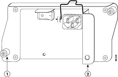
Step 2 ![]() Using a number 2 Phillips or a 3/16-inch flat-blade screwdriver, loosen the two captive installation screws on the faceplate of the power supply. (See Figure 10-1.)
Using a number 2 Phillips or a 3/16-inch flat-blade screwdriver, loosen the two captive installation screws on the faceplate of the power supply. (See Figure 10-1.)
If the router is not installed in a standard 19-inch, 4-post rack or in a telco-type rack, skip to Step 6. If the router is installed in a rack, determine if any permanent rack fixtures, such as a power strip, are obstructing access to the power supply. If a rack fixture is obstructing access to the power supply, proceed to Step 3.
Figure 10-1 Power Supply Captive Installation Screws and Handle—Cisco 7200 Series AC-Input Power Supply Shown
|
|
Captive installation screw |
|
Handle |
Step 3 ![]() Using a 3/16-inch flat-blade screwdriver, loosen the screws that secure the router to the front mounting strips of the rack.
Using a 3/16-inch flat-blade screwdriver, loosen the screws that secure the router to the front mounting strips of the rack.
Step 4 ![]() Position at least one person in front of the rack to support the front underside of the router.
Position at least one person in front of the rack to support the front underside of the router.
Step 5 ![]() From the rear of the rack, carefully push the front of the router out of the rack until there is enough clearance to remove the power supply.
From the rear of the rack, carefully push the front of the router out of the rack until there is enough clearance to remove the power supply.
Step 6 ![]() Grasp the power supply handle and pull the power supply from the router.
Grasp the power supply handle and pull the power supply from the router.
Step 7 ![]() Repeat Step 1 through Step 6 for the other installed power supply (if present).
Repeat Step 1 through Step 6 for the other installed power supply (if present).
This completes the procedure for removing an AC-input or DC-input power supply from a Cisco 7200 series router.
Replacing a Power Supply in a Cisco 7200 Series Router
To install a new AC-input or DC-input power supply in a Cisco 7200 series router, complete the following steps:
Step 1 ![]() Make sure that the power switch on the power supply is in the off (O) position.
Make sure that the power switch on the power supply is in the off (O) position.
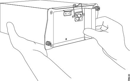
Step 2 ![]() Grasp the power supply handle with one hand and place your other hand underneath the power supply for support. (See Figure 10-2.)
Grasp the power supply handle with one hand and place your other hand underneath the power supply for support. (See Figure 10-2.)
Figure 10-2 Holding the Power Supply—Cisco 7200 Series AC-Input Power Supply Shown
Step 3 ![]() Align the power supply to the power supply bay.
Align the power supply to the power supply bay.
Step 4 ![]() Slide the power supply completely into the power supply bay until its faceplate is flush with the router's rear panel.
Slide the power supply completely into the power supply bay until its faceplate is flush with the router's rear panel.
Step 5 ![]() Seat the power supply in the router by tightening its captive installation screws with a number 2 Phillips or a 3/16-inch flat-blade screwdriver.
Seat the power supply in the router by tightening its captive installation screws with a number 2 Phillips or a 3/16-inch flat-blade screwdriver.
Note ![]() The power supply is not fully seated in the router midplane until you tighten its captive installation screws (use a number 2 Phillips or a 3/16-inch flat-blade screwdriver).
The power supply is not fully seated in the router midplane until you tighten its captive installation screws (use a number 2 Phillips or a 3/16-inch flat-blade screwdriver).
Step 6 ![]() Repeat Step 1 through Step 5 for a second power supply (if present).
Repeat Step 1 through Step 5 for a second power supply (if present).
Step 7 ![]() If there is no second power supply, replace the filler plate on the empty power supply bay. Using a number 2 Phillips or a 3/16-inch flat-blade screwdriver, tighten the filler plate's captive installation screws.
If there is no second power supply, replace the filler plate on the empty power supply bay. Using a number 2 Phillips or a 3/16-inch flat-blade screwdriver, tighten the filler plate's captive installation screws.
Step 8 ![]() If you pushed the router from the rack, slowly guide the router back into the rack.
If you pushed the router from the rack, slowly guide the router back into the rack.
Step 9 ![]() Use a 3/16-inch flat-blade screwdriver to tighten the screws that secure the router to the front mounting strips of the rack.
Use a 3/16-inch flat-blade screwdriver to tighten the screws that secure the router to the front mounting strips of the rack.
Note ![]() When powering on the router, wait a minimum of 30 seconds before powering it off again.
When powering on the router, wait a minimum of 30 seconds before powering it off again.
This completes the procedures for replacing an AC-input or DC-input power supply in a Cisco 7200 series router.
Fiber Optic Cleaning Information
We strongly recommend cleaning all optical connections before reconnecting any optical cables to equipment. For information about cleaning optical connectors, see the Inspection and Cleaning Procedures for Fiber-Optic Connections document and the Compressed Air Cleaning Issues for Fiber-Optic Connections document.
 Feedback