- Preface
- NPE-100, NPE-150, and NPE-200 Overview
- NPE-175 and NPE-225 Overview
- NPE-300 and NPE-400 Overview
- NSE-1 Overview
- NPE-G1 Overview
- NPE-G2 Overview
- NPE-G1 and NPE-G2 Installation and Configuration Information
- Preparation for Installation
- Removing and Installing the NPE or NSE
- Configuration Tasks and Troubleshooting Information
Network Processing Engine and Network Services Engine Installation and Configuration
Bias-Free Language
The documentation set for this product strives to use bias-free language. For the purposes of this documentation set, bias-free is defined as language that does not imply discrimination based on age, disability, gender, racial identity, ethnic identity, sexual orientation, socioeconomic status, and intersectionality. Exceptions may be present in the documentation due to language that is hardcoded in the user interfaces of the product software, language used based on RFP documentation, or language that is used by a referenced third-party product. Learn more about how Cisco is using Inclusive Language.
- Updated:
- November 30, 2006
Chapter: Preparation for Installation
Preparation for Installation
This chapter provides a list of parts and tools you need to remove and replace the network processing engine (NPE) or network services engine (NSE) in:
•![]() Cisco 7200 series routers, including the Cisco 7200 VXR routers
Cisco 7200 series routers, including the Cisco 7200 VXR routers
•![]() Cisco uBR7200 series routers
Cisco uBR7200 series routers
This chapter also includes safety and ESD-prevention guidelines to help you avoid injury to yourself and damage to the equipment. See the "Obtaining Documentation and Submitting a Service Request" section on page iv for ordering and contact information. The following sections are found in this chapter:
•![]() Software and Hardware Requirements
Software and Hardware Requirements
Required Tools and Equipment
You need the following parts and tools to remove and replace an NPE or NSE in Cisco 7200 series routers, Cisco 7200 VXR routers, or Cisco uBR7200 series routers:
•![]() A network processing engine or network services engine (NPE-100, NPE-150, NPE-175, NPE-200, NPE-225, NPE-300, NPE-400, NSE-1, NPE-G1, or NPE-G2)
A network processing engine or network services engine (NPE-100, NPE-150, NPE-175, NPE-200, NPE-225, NPE-300, NPE-400, NSE-1, NPE-G1, or NPE-G2)
•![]() Number 2 Phillips screwdriver and a 3/16-inch flat-blade screwdriver
Number 2 Phillips screwdriver and a 3/16-inch flat-blade screwdriver
•![]() An 8-mm wrench or nut driver, or adjustable wrench (for connecting a grounding lug to a Cisco uBR7200 series DC-input power supply)
An 8-mm wrench or nut driver, or adjustable wrench (for connecting a grounding lug to a Cisco uBR7200 series DC-input power supply)
•![]() A 7-mm wrench or nut driver, or adjustable wrench (for connecting the DC-input power lead strain-relief cover to a DC-input power supply)
A 7-mm wrench or nut driver, or adjustable wrench (for connecting the DC-input power lead strain-relief cover to a DC-input power supply)
•![]() Standard wire stripper (for connecting power to an installed DC-input power supply)
Standard wire stripper (for connecting power to an installed DC-input power supply)
•![]() Tape (for securing the switch handle of a DC circuit breaker in the off position)
Tape (for securing the switch handle of a DC circuit breaker in the off position)
•![]() Your own ESD-prevention equipment or the disposable grounding wrist strap included with all field-replaceable units (FRUs)
Your own ESD-prevention equipment or the disposable grounding wrist strap included with all field-replaceable units (FRUs)
•![]() An antistatic mat or surface, or static-shielding bag
An antistatic mat or surface, or static-shielding bag
•![]() Cable-management brackets and screws that ship with the NPE-G1 or NPE-G2
Cable-management brackets and screws that ship with the NPE-G1 or NPE-G2
If your router is mounted in a 4-post or telco-type rack, make sure you have at least one other person available to assist you with removing the chassis from the rack.
Software and Hardware Requirements
The network processing engine and network services engine have different requirements for both hardware and software. See the "NPE or NSE Requirements" section.

Note ![]() Cisco IOS Release 12.2 changed the behavior of the ROM monitor (ROMmon) during the bootup sequence. See "Boot Changes in Cisco IOS Release 12.2" section on page 10-2 for more information.
Cisco IOS Release 12.2 changed the behavior of the ROM monitor (ROMmon) during the bootup sequence. See "Boot Changes in Cisco IOS Release 12.2" section on page 10-2 for more information.
NPE or NSE Requirements
When installing an NPE-175, NPE-225, NPE-300, NPE-400, NPE-G2, or NSE-1 in a Cisco 7200 VXR router or Cisco uBR7246VXR router that is using a previously purchased I/O controller, you must upgrade the I/O controller boot helper image. The Cisco uBR7225VXR router does not support port adapters or I/O controllers.
Note ![]() Instructions for upgrading the boot helper image on the I/O controller are contained in the online Memory Replacement Instructions for the Network Processing Engine or Network Services Engine and Input/Output Controller publication.
Instructions for upgrading the boot helper image on the I/O controller are contained in the online Memory Replacement Instructions for the Network Processing Engine or Network Services Engine and Input/Output Controller publication.
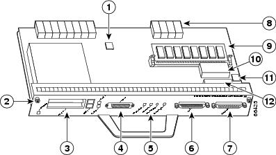
Figure 8-1 Input/Output Controller—Showing Boot ROM and Flash SIMM
Use the following table to determine supported NPEs or the NSE-1 for specific routers.
Port Adapter Jacket Card Support
The Port Adapter Jacket Card inserts into the I/O controller slot of a Cisco 7200 VXR router when an NPE-G2 or NPE-G1 is installed. The Port Adapter Jacket Card network processing engine support is shown in Table 8-3.
|
|
|
|---|---|
NPE-G2 |
Cisco IOS Release 12.4(4)XD2 |
NPE-G1 |
Cisco IOS Release 12.4(4)XD |
Software Requirements
Table 8-4 lists the minimum software requirements for the NPE-400, NPE-G1, and NPE-G2. Table 8-5 and Table 8-6 list the recommended minimum Cisco IOS software release to ensure proper operation of the network processing engine or network services engine in supported router platforms.
|
|
|||
|---|---|---|---|
|
|
|
|
|
|
|
|||
• |
Cisco IOS Release 12.1(3a)E or later releases of 12.1E Cisco IOS Release 12.1(5)T or later releases of 12.1T Cisco IOS Release 12.0(14)S or later releases of 12.0S |
Cisco IOS Release 12.2(4)BW Cisco IOS Release 12.2(8)B or later releases of 12.2 B |
Cisco IOS Release 12.4(4)XD or later releases of 12.4XD. Note |
• |
— |
— |
— |
• |
— |
— |
— |
|
Universal Access Server |
|||
• |
— |
— |
— |
• |
Cisco IOS Release 12.2(5)M or later releases of 12.2M |
— |
— |
|
|
|||
• |
Cisco IOS Release 12.1(6)EC or later releases of 12.1EC with a special boot helper image of 12.0(15)SC [ubr7200-boot-mz.120-15.SC] Cisco IOS Release 12.2(4)BC1 or later releases of 12.2BC Cisco IOS Release 12.3(9a)BC or later releases of 12.3BC |
Cisco IOS Release 12.2(11)CX3 with a special boot helper image of 12.2(11)CX [ubr7200-boot-mz.122-11.CX or ubr7200-kboot-mz.122-11.CX] Cisco IOS Release 12.2(33)SCA or later releases of 12.2S |
Cisco IOS Release 12.2(33)SCA4 Note |
• |
— |
Cisco IOS Release 12.2(33) Cisco IOS Release 12.2(33)SCA with a boot helper image [ubr7200-boot-mz.122-33.SCA] or [ubr7200-kboot-mz.122-33.SCA] |
Cisco IOS Release 12.2S |
1 The NPE-G2 has its own Cisco IOS software image with the prefix "c7200p-" in the software images filenames, including the boot image. The NPE-G2 does not boot up with a software image with the prefix "c7200-". Previous network processing engines, or the network services engine, do not boot up with the "c7200p-" boot image. They use the prefix "c7200-". 2 For information about the Cisco 7206 or Cisco 7206VXR as router shelves in the Cisco AS5800 Universal Access Server, refer to the Cisco AS5800 Universal Access Server documentation listed in the "Related Documentation" section on page iii. 3 The Cisco uBR7246VXR universal broadband router requires the Cisco uBR7200-NPE-G1 version of the NPE-G1. 4 The Cisco uBR7246VXR universal broadband router requires the Cisco uBR7200-NPE-G2 version of the NPE-G2. |
|
|
|
|||
|---|---|---|---|---|
|
|
|
|
|
|
|
|
||||
• |
Cisco IOS Release 12.0(2)XE2 or later releases of 12.0XE |
|||
• |
Cisco IOS Release 11.1(8) |
Cisco IOS Release 11.1(5) |
Cisco IOS Release 12.0 or 12.0S or later releases of 12.0 or 12.0S Cisco IOS Release 11.2(12)P or later releases of 11.2P Cisco IOS Release 11.3(2)T or later releases of 11.3T Cisco IOS Release 11.3(2)AA or later releases of 11.3AA |
— |
• |
— |
Cisco IOS Release 11.3(4)AA or later releases of 11.3AA: Cisco IOS Release 12.0 or 12.0S |
— |
— |
|
Universal Access Server |
||||
• |
— |
— |
Cisco IOS Release 11.3(2)AA or later releases of 11.3AA |
— |
• |
— |
— |
— |
Cisco IOS Release 12.0(4)XJ or later releases of |
|
|
||||
• |
— |
— |
— |
Cisco IOS Release 12.0(6)SC or later releases of 12.0SC Cisco IOS Release 12.1(3)EC1 or later releases of 12.1 EC Cisco IOS Release 12.2(4)BC1 or later releases of 12.2BC |
• |
— |
Cisco IOS Release 11.3(6)NA Cisco IOS Release 12.0(6)SC or later releases of 12.0SC Cisco IOS Release 12.1(3)EC1 or later releases of 12.1EC Cisco IOS Release 12.2(4)BC1 or later releases of 12.2BC |
— |
|
1 The NPE-300 is not supported in the Cisco 7202, Cisco 7204, or Cisco 7206 routers. 2 Cisco IOS Release 12.1(5)T and later releases of 12.1T require a minimum of 128 MB of SRAM or SDRAM. 3 For information about the Cisco 7206 or Cisco 7206VXR as router shelves in the Cisco AS5800 Universal Access Server, refer to the Cisco AS5800 Universal Access Server documentation listed in the "Related Documentation" section on page iii. |
|
|
|||
|---|---|---|---|
|
|
|
|
|
|
|
|||
• |
Cisco IOS Release 12.0(4)XE or later releases of 12.0XE Cisco IOS Release 12.0(5)T or later releases of 12.0T |
Cisco IOS Release 12.1E or Cisco IOS Release 12.1(5)T or later releases of 12.1T |
|
• |
Cisco IOS Release 12.0(4)XE or later releases of 12.0XE Cisco IOS Release 12.0(5)T or later releases of 12.0T |
— |
|
|
|
|||
• |
— |
Cisco IOS Release 12.0(6)SC or later releases of 12.0SC Cisco IOS Release 12.1(3)EC1 or later releases of 12.1 EC Cisco IOS Release 12.2(4)BC1 or later releases of 12.2BC |
— |
1 Cisco IOS Release 12.1(5)T and later releases of 12.1T require a minimum of 128 MB of SRAM or SDRAM. 2 Previous documents stated that the Cisco uBR7200 series routers supported the NPE-175. Because the NPE-175 has reached its end of life and was never made orderable for the Cisco uBR7200 series routers, the NPE-175 is no longer shown as supported for the Cisco uBR7200 series routers. |
Safety Guidelines
Following are safety guidelines that you should follow when working with any equipment that connects to electrical power or telephone wiring.

Warning ![]() Only trained and qualified personnel should be allowed to install or replace this equipment.
Only trained and qualified personnel should be allowed to install or replace this equipment.
Statement 1030
Safety Warnings


Electrical Equipment Guidelines
Follow these basic guidelines when working with any electrical equipment:
•![]() Before beginning any procedures requiring access to the chassis interior, locate the emergency power-off switch for the room in which you are working.
Before beginning any procedures requiring access to the chassis interior, locate the emergency power-off switch for the room in which you are working.
•![]() Disconnect all power and external cables before moving a chassis.
Disconnect all power and external cables before moving a chassis.
•![]() Do not work alone when potentially hazardous conditions exist.
Do not work alone when potentially hazardous conditions exist.
•![]() Never assume that power has been disconnected from a circuit; always check.
Never assume that power has been disconnected from a circuit; always check.
•![]() Do not perform any action that creates a potential hazard to people or makes the equipment unsafe.
Do not perform any action that creates a potential hazard to people or makes the equipment unsafe.
•![]() Carefully examine your work area for possible hazards such as moist floors, ungrounded power extension cables, and missing safety grounds.
Carefully examine your work area for possible hazards such as moist floors, ungrounded power extension cables, and missing safety grounds.
Telephone Wiring Guidelines
Use the following guidelines when working with any equipment that is connected to telephone wiring or to other network cabling:
•![]() Never install telephone wiring during a lightning storm.
Never install telephone wiring during a lightning storm.
•![]() Never install telephone jacks in wet locations unless the jack is specifically designed for wet locations.
Never install telephone jacks in wet locations unless the jack is specifically designed for wet locations.
•![]() Never touch uninsulated telephone wires or terminals unless the telephone line has been disconnected at the network interface.
Never touch uninsulated telephone wires or terminals unless the telephone line has been disconnected at the network interface.
•![]() Use caution when installing or modifying telephone lines.
Use caution when installing or modifying telephone lines.
Electrostatic Discharge Prevention
Electrostatic discharge (ESD) damages equipment and impairs electrical circuitry. ESD occurs when printed circuit boards are improperly handled and results in complete or intermittent failures.
The network processing engine or network services engine, I/O controller, port adapters, and Cisco uBR7200 series cable interface line cards consist of printed circuit boards that are fixed in a metal carrier. Electromagnetic interference (EMI) shielding, connectors, and a handle are integral components of the carrier. Handle the network processing engine or network services engine, I/O controller, port adapters, and Cisco uBR7200 series cable interface line cards by their carrier edges and handles; never touch the printed circuit board or connector pins.
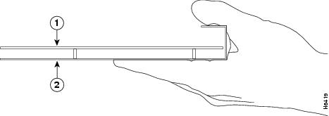
Figure 8-2 shows the location of a printed circuit board in a network processing engine or network services engine, I/O controller, or Cisco uBR7200 series cable interface line card metal carrier. Do not touch the printed circuit board when handling any of the components.
Figure 8-2 Handling the Network Processing Engine or Network Services Engine, the I/O Controller, and the Cisco uBR7200 Series Cable Interface Line Cards—Side View
|
|
Printed circuit board |
|
Metal carrier |
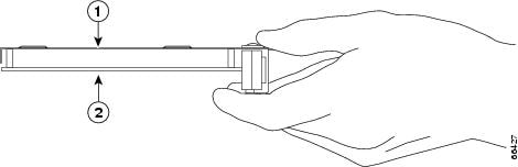
Figure 8-3 shows the location of a printed circuit board in a port adapter metal carrier. Do not touch the printed circuit board when handling a port adapter.
Figure 8-3 Handling a Port Adapter—Side View
|
|
Metal carrier |
|
Printed circuit board |
Although the metal carrier helps to protect the printed circuit boards from ESD, wear a preventive antistatic strap whenever handling the network processing engine or network services engine, I/O controller, port adapters, or Cisco uBR7200 series cable interface line cards. Ensure that the strap makes good skin contact and connect the strap's clip to an unpainted chassis surface to channel unwanted ESD voltages safely to ground.
If no wrist strap is available, ground yourself by touching the metal part of the chassis.

Following are guidelines for preventing ESD damage:
•![]() Always use an ESD wrist strap or ankle strap when installing or replacing the network processing engine or network services engine, I/O controller, port adapters, or Cisco uBR7200 series cable interface line cards. Ensure that the ESD strap makes contact with your skin.
Always use an ESD wrist strap or ankle strap when installing or replacing the network processing engine or network services engine, I/O controller, port adapters, or Cisco uBR7200 series cable interface line cards. Ensure that the ESD strap makes contact with your skin.
•![]() Handle the network processing engine or network services engine, I/O controller, port adapters, or Cisco uBR7200 series cable interface line cards by their metal carrier edges and handles only; avoid touching the printed circuit board components or any connector pins.
Handle the network processing engine or network services engine, I/O controller, port adapters, or Cisco uBR7200 series cable interface line cards by their metal carrier edges and handles only; avoid touching the printed circuit board components or any connector pins.
•![]() When removing the network processing engine or network services engine, I/O controller, port adapters, or Cisco uBR7200 series cable interface line cards, place them on an antistatic surface with the printed circuit board components facing upward, or in a static shielding bag. If you are returning an I/O controller, network processing engine or network services engine, port adapter, or Cisco uBR7200 series cable interface line card to the factory, immediately place it in a static shielding bag.
When removing the network processing engine or network services engine, I/O controller, port adapters, or Cisco uBR7200 series cable interface line cards, place them on an antistatic surface with the printed circuit board components facing upward, or in a static shielding bag. If you are returning an I/O controller, network processing engine or network services engine, port adapter, or Cisco uBR7200 series cable interface line card to the factory, immediately place it in a static shielding bag.
 Feedback