Table Of Contents
Cisco 10720 Internet Router Cable Management and Rack Mount Installation Instructions
Preventing Electrostatic Discharge
Rack Mounting Clearance Guidelines
Multiple Routers in a Rack Maintenance Guidelines
Cisco 10720 Internet Router Setup Checklist
Installing the Cable-Management System
Removing the Cable-Management System
Obtaining Technical Assistance
Contacting TAC by Using the Cisco TAC Website
Electromagnetic Compatibility Regulatory Statements
Site Wiring Distance and Interference Guidelines
Distance Limitations for Signaling and Unshielded Conductors
Cisco 10720 Internet Router Cable Management and Rack Mount Installation Instructions
Customer Order Number: DOC-7813101=
Product Number: 10720-ACCKIT=
This publication contains instructions to set up and mount the router on the mounting rack and to install and remove the cable-management system provided in the accessory kit for the Cisco 10720 Internet Router.
Refer to Cisco 10720 Internet Router Installation and Configuration Guide for more information about this product line.
This publication uses the following terminology to refer to the Cisco 10720 Internet Router, cable-management and rack mount:
Cisco 10720 Internet Router
router
Cisco 10720 Internet Router Cable-Management
cable-management system
Cisco 10720 Internet Router Rack Mount
rack mount
Contents
Cisco 10720 Internet Router Setup Checklist
Installing the Cable-Management System
Removing the Cable-Management System
Obtaining Technical Assistance
–
Contacting TAC by Using the Cisco TAC Website
Overview
The Cisco 10720 Internet Router can be mounted in a variety of ways:
•
–
–
–
•
•
The cable-management system, located on the front of the Cisco 10720 Internet Router, organizes the interface cables that lead into and away from the router. To keep the cables free of sharp bends, extend the cables from the center out both sides of the cable-management tray. Excessive bending in an interface cable can degrade performance and possibly harm the cable.
The cable-management system consists of the following components:
•
•
Caution
You must power down your router before maintaining any field replaceable unit (FRU) module.
Tools and Equipment Required
You will need the following tools and equipment to install and remove the cable-management system and to mount the router:
•
•
•
•
•
Safety
This publication contains important safety information that you must read and understand before attempting to install, remove, or modify any hardware in your router. For more safety information, see the "Electromagnetic Compliance" section and the "Translated Safety Warnings" section.
For information about regulatory compliance and safety, see the Regulatory Compliance and Safety Information for the Cisco 10720 Internet Router publication that shipped with your router.
Please review the safety guidelines in the following sections to avoid injuring yourself or damaging the equipment:
Safety Warnings
Before mounting the router or installing the cable-management system, read the following safety guidelines:
Caution
Warning
Warning
Warning
Disconnect Device Warnings
The Cisco 10720 Internet Router power source must be disconnected before performing any maintenance task on the hardware modules. Please refer to the safety warnings in the "Disconnecting Power from the Router" section of Chapter 5, "Maintaining the Cisco 10720 Internet Router", in the Cisco 10720 Internet Router Installation and Configuration Guide.
Electrostatic Discharge
Electrostatic discharge (ESD) can damage circuit boards and other electronic equipment if they are handled improperly. Such mishandling can result in intermittent or complete failures of the board or other components of the router.
When handling router components, observe the following guidelines to prevent ESD damage:
•
•
•
Caution
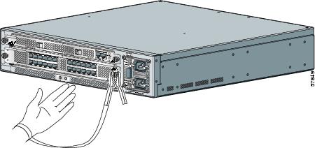
Preventing Electrostatic Discharge
Electrostatic discharge (ESD) damage can cause complete or intermittent equipment failures. Cisco recommends using an ESD-preventive strap when you handle a router or one of its components. Electromagnetic interference (EMI) shielding is an integral component of the router.
Following are guidelines for preventing ESD damage:
•
Figure 1 Attaching an ESD-Preventive Strap
•
Rack Mounting Guidelines
Before installing the Cisco 10720 Internet Router in a 19-inch EIA, 23/24-inch EIA or ETSI equipment rack, consider the following general rack-mounting guidelines:
•
•
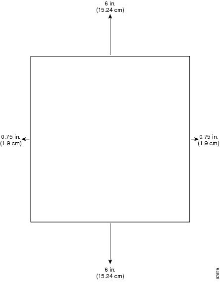
Ventilation Guidelines
Caution
The following section provides information and guidelines to provide adequate ventilation for the Cisco 10720 Internet Router:
•
•
•
Note
•
See Figure 2 for the ventilation requirements of the Cisco 10720 Internet Router.
Figure 2 Ventilation Requirements for Cisco 10720 Internet Router
Rack Mounting Clearance Guidelines
The rack-mounting hardware included with the Cisco 10720 Internet Router is suitable for most 19-inch EIA, 23- or 24-inch EIA or ETSI equipment racks or telco-style racks.
The following are rack-mounting guidelines for the Cisco 10720 Internet Router:
•
•
Note
Multiple Routers in a Rack Maintenance Guidelines
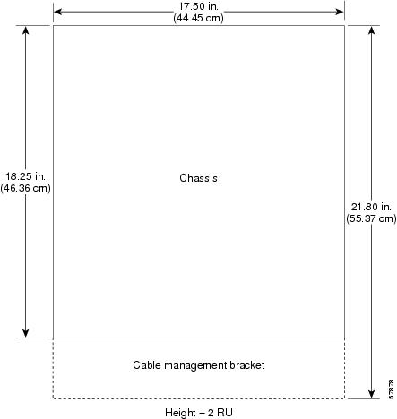
The Cisco 10720 Internet Router is 17.50 (44.45 cm) W x 3.45 (8.76 cm) H (2 RU) x 18.25 inches (46.36 cm) D. When the cable-management tray is installed the router is 21.80 inches (55.37 cm) D. When placing multiple routers in a rack, ensure there is sufficient ventilation to accommodate each router.
The heated exhaust air from other equipment can enter the inlet air vents and cause an overtemperature condition inside the router.
•
•
•
Figure 3 illustrates the outer dimensions of the Cisco 10720 Internet Router.
Figure 3 Cisco 10720 Internet Router Outer Dimensions (Top View
Cisco 10720 Internet Router Setup Checklist
Before you install your Cisco 10720 Internet Router, verify the following:
Note
Ensure that you have considered the following before you install the router:
•
•
•
•
•
•
•
Installing the Cable-Management System
Perform the following steps to install the cable-management system:
Step 1
Step 2
Step 3
Figure 4 Attaching Cable-Management Tray
Step 4
Step 5
Note
Figure 5 Managing Router Cables with the Cable-Management Tray
Step 6
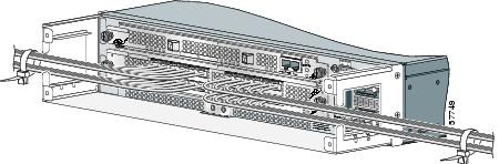
Figure 6 Cable-Management Installed in the Rack
Step 7
Step 8
Figure 7 Installing the Cable-Management Cover
Removing the Cable-Management System
Perform the following steps to remove the cable-management system:
Step 1
Step 2
Step 3
Figure 8 Removing the Cable-Management Cover
Caution
Step 4
Step 5
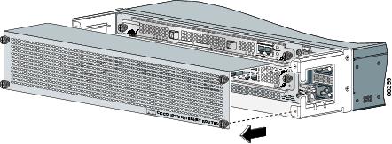
Figure 9 Removing the Cable-Management Tray
Rack Mounting the Router
This section demonstrates how to mount the Cisco 10720 Internet Router on an equipment rack, wall, or desktop. The Cisco 10720 Internet Router comes with three sets of brackets for rack mounting, one set of brackets for wall mounting and four rubber foot pads for desk mounting.
Check the clearance around the router before installation. (See the "Rack Mounting Guidelines" section.)
Note
The following rack mounting steps describe how to mount the router on a 19-inch, 23- and 24-inch, or ETSI rack:
Step 1
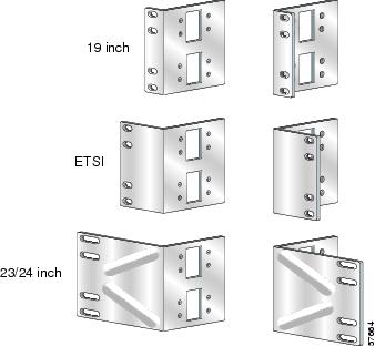
Figure 10 Cisco 10720 Internet Router Rack Mounts
Step 2
Step 3
Step 4
Step 5
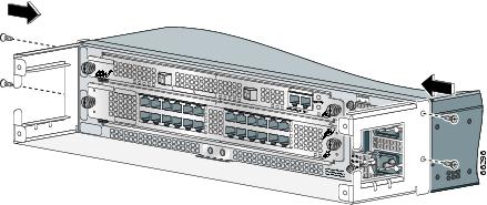
Step 6
•
•
•
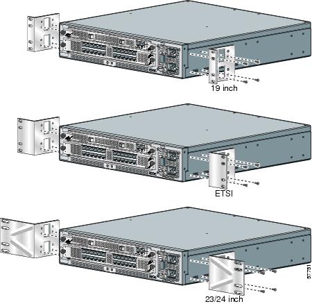
Figure 11 Installing Rack Mounts
Step 7
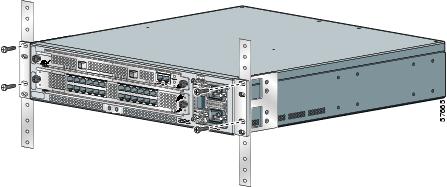
Figure 12 Attaching the Router to the 19-Inch Rack (Front Panel Forward)
Wall Mounting the Router
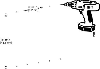
The wall mount brackets must be mounted on a minimum 5/8" (15.9 mm) wallboard gypsum or equivalent with twelve 1 1/4" No. 10 screws or equivalent (M5 x 31.8 mm).
Caution
The following steps illustrate hot to set up a proper and secure wall mount for the router. These steps ensure adequate ventilation is available at all times. A Number 1 Phillips screwdriver is required to perform the following procedure:
Step 1
Note
Step 2
Figure 13 Predrilled 12 holes
Step 3
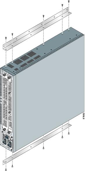
Step 4
Figure 14 Attaching Wall Mount Brackets to Router Chassis
Note
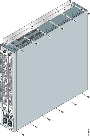
Step 5
Note
Figure 15 Rack Wall Mount
Obtaining Technical Assistance
Cisco provides Cisco.com as a starting point for all technical assistance. Customers and partners can obtain documentation, troubleshooting tips, and sample configurations from online tools. For Cisco.com registered users, additional troubleshooting tools are available from the TAC website.
Technical assistance information is presented in the following sections:
Contacting Cisco
Cisco provides Cisco.com as a starting point for all technical assistance. Customers and partners can obtain documentation, troubleshooting tips, and sample configurations from online tools. For Cisco.com registered users, additional troubleshooting tools are available from the TAC website.
Cisco.com
Cisco.com is the foundation of a suite of interactive, networked services that provides immediate, open access to Cisco information and resources at anytime, from anywhere in the world. This highly integrated Internet application is a powerful, easy-to-use tool for doing business with Cisco.
Cisco.com provides a broad range of features and services to help customers and partners streamline business processes and improve productivity. Through Cisco.com, you can find information about Cisco and our networking solutions, services, and programs. In addition, you can resolve technical issues with online technical support, download and test software packages, and order Cisco learning materials and merchandise. Valuable online skill assessment, training, and certification programs are also available.
Customers and partners can self-register on Cisco.com to obtain additional personalized information and services. Registered users can order products, check on the status of an order, access technical support, and view benefits specific to their relationships with Cisco.
To access Cisco.com, go to the following website:
http://www.cisco.com
Technical Assistance Center
The Cisco TAC website is available to all customers who need technical assistance with a Cisco product or technology that is under warranty or covered by a maintenance contract.
Contacting TAC by Using the Cisco TAC Website
If you have a priority level 3 (P3) or priority level 4 (P4) problem, contact TAC by going to the TAC website:
http://www.cisco.com/tac
P3 and P4 level problems are defined as follows:
•
•
In each of the above cases, use the Cisco TAC website to quickly find answers to your questions.
To register for Cisco.com, go to the following website:
http://www.cisco.com/register/
If you cannot resolve your technical issue by using the TAC online resources, Cisco.com registered users can open a case online by using the TAC Case Open tool at the following website:
http://www.cisco.com/tac/caseopen
Contacting TAC by Telephone
If you have a priority level 1(P1) or priority level 2 (P2) problem, contact TAC by telephone and immediately open a case. To obtain a directory of toll-free numbers for your country, go to the following website:
http://www.cisco.com/warp/public/687/Directory/DirTAC.shtml
P1 and P2 level problems are defined as follows:
•
•
World Wide Web
You can access the most current Cisco documentation on the World Wide Web at the following sites:
•
•
•
Related Documentation
The following section provides some reference material out of the Cisco.com library that may be useful for configuring and maintaining the Cisco 10720 Internet Router:
•
•
Obtaining Documentation
The following sections provide sources for obtaining documentation from Cisco Systems. Access to documentation is presented in the following sections:
Documentation CD-ROM
Cisco documentation and additional literature are available in a CD-ROM package, which ships with your product. The Documentation CD-ROM is updated monthly and might be more current than printed documentation. The CD-ROM package is available as a single unit or as an annual subscription.
Ordering Documentation
Cisco documentation is available in the following ways:
•
http://www.cisco.com/cgi-bin/order/order_root.pl
•
http://www.cisco.com/go/subscription
•
–
–
Documentation Feedback
If you are reading Cisco product documentation on the World Wide Web, you can submit technical comments electronically. Click Feedback in the toolbar and select Documentation. After you complete the form, click Submit to send it to Cisco.
You can e-mail your comments to bug-doc@cisco.com.
To submit your comments by mail, use the response card behind the front cover of your document, or write to the following address:
Attn. Document Resource Connection
Cisco Systems, Inc.
170 West Tasman Drive
San Jose, CA 95134-9883We appreciate your comments.
Electromagnetic Compliance
Safety compliance information is presented in the following sections:
•
•
Electromagnetic Compatibility Regulatory Statements
FCC Class A Compliance
This equipment has been tested and found to comply with the limits for a Class A digital device, pursuant to part 15 of the FCC rules. These limits are designed to provide reasonable protection against harmful interference when the equipment is operated in a commercial environment. This equipment generates, uses, and can radiate radio-frequency energy and, if not installed and used in accordance with the instruction manual, may cause harmful interference to radio communications. Operation of this equipment in a residential area is likely to cause harmful interference, in which case users will be required to correct the interference at their own expense.
Modifying the equipment without Cisco's authorization may result in the equipment no longer complying with FCC requirements for Class A digital devices. In that event, your right to use the equipment may be limited by FCC regulation and you may be required to correct any interference to radio or television communication at your own expense.
You can determine whether your equipment is causing interference by turning it off. If the interference stops, it was probably caused by the Cisco equipment or one of its peripheral devices. If the equipment causes interference to radio or television reception, try to correct the interference by using one or more of the following measures:
•
•
•
•
CISPR 22
Warning
Note
Note
Canada
English Statement of Compliance
This class A digital apparatus complies with Canadian ICES-003.
French Statement of Compliance
Cet appareil numérique de la classe A est conforme à la norme NMB-003 du Canada.
Europe (EU)
This apparatus complies with EN55022 Class A and EN55024 standards when used as ITE/TTE equipment, and EN 300 386-2 (EN55022 class B with shielded CAT5 Ethernet cable, non-central office equipment) for Telecommunications Network Equipment (TNE).
Hungarian Class A Warning
Figyelmeztetés a felhasználói kézikönyv számára:
Ez a berendezés "A" osztályú termék, felhasználására és üzembe helyezésére a magyar EMC "A" osztályú követelményeknek (MSZ EN 55022) megfelelõen kerülhet sor, illetve ezen "A" osztályú berendezések csak megfelelõ kereskedelmi forrásból származhatnak, amelyek biztosítják a megfelelõ speciális üzembe helyezési körülményeket és biztonságos üzemelési távolságok alkalmazását.
This equipment is a class A product and should be used and installed properly according to the Hungarian EMC Class A requirements (MSZEN55022). The Class A equipment are derived for typical commercial establishments for which special conditions of installation and protection distance are used.
Taiwan Class A Warning
This is a class A product. In a domestic environment this product may cause radio interference in which case you may be required to take adequate measures.
Note
Japan VCCI Class A
This is a Class A product based on the standard of the Voluntary Control Council for Interference by Information Technology Equipment (VCCI). If this equipment is used in a domestic environment, radio disturbance may arise. When such trouble occurs, the user may be required to take corrective actions.
Korean Class A Warning
Class A device. This device is registered for EMC requirements for industrial use. The seller or buyer should be aware of this. If this type was sold or purchased by mistake, it should be replaced with a residential-use type.
Site Wiring Distance and Interference Guidelines
This section offers site wiring guidelines for setting up the site plant wiring and cabling. When planning the location of the new system, consider the following:
•
Electromagnetic Interference
Electromagnetic interference can occur between the field and the signals on the wires when the wires are run for any significant distance. This fact has two implications for the construction of plant wiring:
•
•
Note
A good quality twisted pair cable or shielded twisted pair cable helps limit radiation and noise induced into the cable minimizing,
•
•
Distance Limitations for Signaling and Unshielded Conductors
Give special consideration to the effect of a lightning strike in the site vicinity if wires exceed recommended distances, or if wires pass between buildings. The electromagnetic pulse (EMP) caused by lightning or other high-energy phenomena can easily couple enough energy into unshielded conductors to destroy electronic devices.
Provide a properly grounded and shielded environment. Consider electrical surge suppression issues by addressing the following items:
•
•
Caution
Translated Safety Warnings
Safety warnings appear throughout this publication in procedures that, if performed incorrectly, may harm you. A warning symbol precedes each warning statement. The following paragraph is an example of a safety warning. It identifies the warning symbol and associates it with a bodily injury hazard. The remaining paragraphs in this section are translations of the initial safety warning.
Note
This document is to be used in conjunction with the documents listed in the Cisco 10720 Internet RouterInstallation and Configuration Guide.
Copyright © 2003 Cisco Systems, Inc. All rights reserved.
Guest