VPN Availability Configuration Guide, Cisco IOS Release 15.1M&T
Bias-Free Language
The documentation set for this product strives to use bias-free language. For the purposes of this documentation set, bias-free is defined as language that does not imply discrimination based on age, disability, gender, racial identity, ethnic identity, sexual orientation, socioeconomic status, and intersectionality. Exceptions may be present in the documentation due to language that is hardcoded in the user interfaces of the product software, language used based on RFP documentation, or language that is used by a referenced third-party product. Learn more about how Cisco is using Inclusive Language.
- Updated:
- March 28, 2011
Chapter: IPsec VPN High Availability Enhancements
- Finding Feature Information
- Contents
- Information About IPsec VPN High Availability Enhancements
- How to Configure IPsec VPN High Availability Enhancements
- Configuration Examples for IPsec VPN High Availability Enhancements
- Additional References
- Feature Information for IPsec VPN High Availability Enhancements
IPsec VPN High Availability Enhancements
The IPsec VPN High Availability Enhancements feature consists of two features—Reverse Route Injection (RRI) and Hot Standby Router Protocol and IPsec (HSRP). When used together, these two features work together to provide users with a simplified network design for VPNs and reduced configuration complexity on remote peers with respect to defining gateway lists.
Finding Feature Information
Your software release may not support all the features documented in this module. For the latest feature information and caveats, see the release notes for your platform and software release. To find information about the features documented in this module, and to see a list of the releases in which each feature is supported, see the "Feature Information for IPsec VPN High Availability Enhancements" section.
Use Cisco Feature Navigator to find information about platform support and Cisco software image support. To access Cisco Feature Navigator, go to http://www.cisco.com/go/cfn. An account on Cisco.com is not required.
Contents
•![]() Information About IPsec VPN High Availability Enhancements
Information About IPsec VPN High Availability Enhancements
•![]() How to Configure IPsec VPN High Availability Enhancements
How to Configure IPsec VPN High Availability Enhancements
•![]() Configuration Examples for IPsec VPN High Availability Enhancements
Configuration Examples for IPsec VPN High Availability Enhancements
•![]() Feature Information for IPsec VPN High Availability Enhancements
Feature Information for IPsec VPN High Availability Enhancements
Information About IPsec VPN High Availability Enhancements
To configure the IPsec VPN High Availability Enhancements feature, you should understand the following concepts:
•![]() Hot Standby Router Protocol and IPsec
Hot Standby Router Protocol and IPsec
Reverse Route Injection
Reverse Route Injection (RRI) simplifies network design for Virtual Private Networks (VPNs) in which there is a requirement for redundancy or load balancing. RRI works with both dynamic and static crypto maps.
RRI provides the following benefits:
•![]() Enables routing of IPsec traffic to a specific VPN headend device in environments that have multiple (redundant) VPN headend devices.
Enables routing of IPsec traffic to a specific VPN headend device in environments that have multiple (redundant) VPN headend devices.
•![]() Ensures predictable failover time of remote sessions between headend devices when using IKE keepalives, especially in environments in which remote device route flapping is common (not taking into consideration the effects of route convergence, which may vary depending on the routing protocol used and the size of the network).
Ensures predictable failover time of remote sessions between headend devices when using IKE keepalives, especially in environments in which remote device route flapping is common (not taking into consideration the effects of route convergence, which may vary depending on the routing protocol used and the size of the network).
•![]() Eliminates the need for the administration of static routes on upstream devices, as routes are dynamically learned by these devices.
Eliminates the need for the administration of static routes on upstream devices, as routes are dynamically learned by these devices.
In the dynamic case, as remote peers establish IPsec security associations (SAs) with an RRI-enabled router, a static route is created for each subnet or host protected by that remote peer. For static crypto maps, a static route is created for each destination of an extended access list rule. When RRI is used on a static crypto map with an access control list (ACL), routes will always exist, even without the negotiation of IPsec SAs.

Note ![]() Use of any keyword in ACLs with RRI is not supported.
Use of any keyword in ACLs with RRI is not supported.
When routes are created, they are injected into any dynamic routing protocol and distributed to surrounding devices. This traffic flows, requiring IPsec to be directed to the appropriate RRI router for transport across the correct SAs to avoid IPsec policy mismatches and possible packet loss.
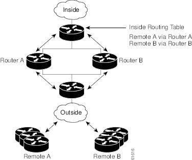
Figure 1 shows a RRI configuration functionality topology. Remote A is being serviced by Router A and Remote B connected to Router B, providing load balancing across VPN gateways at the central site. RRI on the central site devices ensures that the other router on the inside of the network can automatically make the correct forwarding decision. RRI also eliminates the need to administer static routes on the inside router.
Figure 1 Topology Showing Reverse Route Injection Configuration Functionality
Hot Standby Router Protocol and IPsec
Hot Standby Router Protocol (HSRP) provides high network availability by routing IP traffic from hosts on Ethernet networks without relying on the availability of any single router. HSRP is particularly useful for hosts that do not support a router discovery protocol, such as ICMP Router Discovery Protocol (IRDP) and do not have the functionality to switch to a new router when their selected router reloads or loses power. Without this functionality, a router that loses its default gateway because of a router failure cannot communicate with the network.
HSRP is configurable on LAN interfaces using standby command-line interface (CLI) commands. It is now possible to use the standby IP address from an interface as the local IPsec identity or local tunnel endpoint.
By using the standby IP address as the tunnel endpoint, failover can be applied to VPN routers by using HSRP. Remote VPN gateways connect to the local VPN router via the standby address that belongs to the active device in the HSRP group. In the event of failover, the standby device takes over ownership of the standby IP address and begins to service remote VPN gateways.
Failover can be applied to VPN routers through the use of HSRP. Remote VPN gateways connect to the local VPN router through the standby address that belongs to the active device in the HSRP group. This functionality reduces configuration complexity on remote peers with respect to defining gateway lists, because only the HSRP standby address needs to be defined.
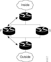
Figure 2 shows the enhanced HSRP functionality topology. Traffic is serviced by the active Router P, the active device in the standby group. In the event of failover, traffic is diverted to Router S, the original standby device. Router S assumes the role of the new active router and takes ownership of the standby IP address.
Figure 2 Topology Showing Hot Standby Router Protocol Functionality
Note ![]() In case of a failover, HSRP does not facilitate IPsec state information transference between VPN routers. This means that without this state transference, SAs to remotes will be deleted, requiring Internet Key Exchange (IKE) and IPsec SAs to be reestablished. To make IPsec failover more efficient, it is recommended that IKE keepalives be enabled on all routers.
In case of a failover, HSRP does not facilitate IPsec state information transference between VPN routers. This means that without this state transference, SAs to remotes will be deleted, requiring Internet Key Exchange (IKE) and IPsec SAs to be reestablished. To make IPsec failover more efficient, it is recommended that IKE keepalives be enabled on all routers.
How to Configure IPsec VPN High Availability Enhancements
This section contains the following procedures:
•![]() Configuring Reverse Route Injection on a Dynamic Crypto Map (required)
Configuring Reverse Route Injection on a Dynamic Crypto Map (required)
•![]() Configuring Reverse Route Injection on a Static Crypto Map (required)
Configuring Reverse Route Injection on a Static Crypto Map (required)
•![]() Configuring HSRP with IPsec (required)
Configuring HSRP with IPsec (required)
•![]() Verifying VPN IPsec Crypto Configuration (optional)
Verifying VPN IPsec Crypto Configuration (optional)
Configuring Reverse Route Injection on a Dynamic Crypto Map
Dynamic crypto map entries, like regular static crypto map entries, are grouped into sets. A set is a group of dynamic crypto map entries all with the same dynamic map name, but each with a different dynamic sequence number. Each member of the set may be configured for RRI.
To create a dynamic crypto map entry and enable RRI, perform the steps in this section.
SUMMARY STEPS
1. ![]() enable
enable
2. ![]() configure terminal
configure terminal
3. ![]() crypto dynamic-map map-name seq-num
crypto dynamic-map map-name seq-num
4. ![]() set transform-set
set transform-set
5. ![]() reverse-route
reverse-route
DETAILED STEPS
Configuring Reverse Route Injection on a Static Crypto Map
Before configuring RRI on a static crypto map, note that:
•![]() Routes are not created based on access list 102, as reverse-route is not enabled on mymap 2. RRI is not enabled by default and is not displayed in the router configuration.
Routes are not created based on access list 102, as reverse-route is not enabled on mymap 2. RRI is not enabled by default and is not displayed in the router configuration.
•![]() Enable a routing protocol to distribute the VPN routes to upstream devices.
Enable a routing protocol to distribute the VPN routes to upstream devices.
•![]() If Cisco Express Forwarding (CEF) is run on a VPN router configured for RRI, adjacencies need to be formed for each RRI injected network through the next hop device. As the next hop is not explicitly defined in the routing table for these routes, proxy-ARP should be enabled on the next hop router, which allows the CEF adjacency to be formed using the layer two addresses of that device. In cases where there are many RRI injected routes, adjacency tables may become quite large, as an entry is created for each device from each of the subnets represented by the RRI route. This issue is to be resolved in a future release.
If Cisco Express Forwarding (CEF) is run on a VPN router configured for RRI, adjacencies need to be formed for each RRI injected network through the next hop device. As the next hop is not explicitly defined in the routing table for these routes, proxy-ARP should be enabled on the next hop router, which allows the CEF adjacency to be formed using the layer two addresses of that device. In cases where there are many RRI injected routes, adjacency tables may become quite large, as an entry is created for each device from each of the subnets represented by the RRI route. This issue is to be resolved in a future release.
To add RRI to a static crypto map set, perform the steps in this section.
SUMMARY STEPS
1. ![]() enable
enable
2. ![]() configure terminal
configure terminal
3. ![]() crypto map map-name seq-num ipsec-isakmp
crypto map map-name seq-num ipsec-isakmp
4. ![]() set peer ip-address
set peer ip-address
5. ![]() reverse-route
reverse-route
6. ![]() match address
match address
7. ![]() set transform-set
set transform-set
DETAILED STEPS
Configuring HSRP with IPsec
When configuring HSRP with IPsec, the following conditions may apply:
•![]() When HSRP is applied to a crypto map on an interface, the crypto map must be reapplied if the standby IP address or the standby name is changed on that interface.
When HSRP is applied to a crypto map on an interface, the crypto map must be reapplied if the standby IP address or the standby name is changed on that interface.
•![]() If HSRP is applied to a crypto map on an interface, and the user deletes the standby IP address or the standby name from that interface, the crypto tunnel endpoint is reinitialized to the actual IP address of that interface.
If HSRP is applied to a crypto map on an interface, and the user deletes the standby IP address or the standby name from that interface, the crypto tunnel endpoint is reinitialized to the actual IP address of that interface.
•![]() If a user adds the standby IP address and the standby name to an interface with the requirement IPsec failover, the crypto map must be reapplied with the appropriate redundancy information.
If a user adds the standby IP address and the standby name to an interface with the requirement IPsec failover, the crypto map must be reapplied with the appropriate redundancy information.
•![]() Standby priorities should be equal on active and standby routers. If they are not, the higher priority router takes over as the active router. If the old active router comes back up and immediately assumes the active role before having time to report itself standby and sync, connections will be dropped.
Standby priorities should be equal on active and standby routers. If they are not, the higher priority router takes over as the active router. If the old active router comes back up and immediately assumes the active role before having time to report itself standby and sync, connections will be dropped.
•![]() The IP addresses on the HSRP-tracked interfaces on the standby and active routers should both be either lower or higher on one router than the other. In the case of equal priorities (an HA requirement), HSRP will assign the active state-based IP address. If an addressing scheme exists so that the public IP address of router A is lower than the public IP address of router B, but the opposite is true for their private interfaces, an active/standby-standby/active split condition could exist, which will break connectivity.
The IP addresses on the HSRP-tracked interfaces on the standby and active routers should both be either lower or higher on one router than the other. In the case of equal priorities (an HA requirement), HSRP will assign the active state-based IP address. If an addressing scheme exists so that the public IP address of router A is lower than the public IP address of router B, but the opposite is true for their private interfaces, an active/standby-standby/active split condition could exist, which will break connectivity.
Note ![]() To configure HSRP without IPsec, refer to the "Configuring IP Services" module in the Cisco IOS IP Application Services Configuration Guide
To configure HSRP without IPsec, refer to the "Configuring IP Services" module in the Cisco IOS IP Application Services Configuration Guide
To apply a crypto map set to an interface, perform the steps in this section.
SUMMARY STEPS
1. ![]() enable
enable
2. ![]() configure terminal
configure terminal
3. ![]() interface type slot/port
interface type slot/port
4. ![]() standby name group-name
standby name group-name
5. ![]() standby ip ip-address
standby ip ip-address
6. ![]() crypto map map-name redundancy [standby-name]
crypto map map-name redundancy [standby-name]
DETAILED STEPS
Verifying VPN IPsec Crypto Configuration
To verify your VPN IPsec crypto configuration, perform the steps in this section.
SUMMARY STEPS
1. ![]() enable
enable
2. ![]() show crypto ipsec transform-set
show crypto ipsec transform-set
3. ![]() show crypto map [interface interface | tag map-name]
show crypto map [interface interface | tag map-name]
4. ![]() show crypto ipsec sa [map map-name | address | identity] [detail]
show crypto ipsec sa [map map-name | address | identity] [detail]
5. ![]() show crypto dynamic-map [tag map-name]
show crypto dynamic-map [tag map-name]
DETAILED STEPS
Configuration Examples for IPsec VPN High Availability Enhancements
This section provides the following configuration examples:
•![]() Example: Reverse Route Injection on a Dynamic Crypto Map
Example: Reverse Route Injection on a Dynamic Crypto Map
•![]() Example: Reverse Route Injection on a Static Crypto Map
Example: Reverse Route Injection on a Static Crypto Map
Example: Reverse Route Injection on a Dynamic Crypto Map
In the following example, using the reverse-route command in the definition of the dynamic crypto map template ensures that routes are created for any remote proxies (subnets or hosts), protected by the connecting remote IPsec peers.
crypto dynamic mydynmap 1
set transform-set esp-3des-sha
reverse-route
This template is then associated with a "parent" crypto map statement and then applied to an interface.
crypto map mymap 3 ipsec-isakmp dynamic mydynmap
interface FastEthernet 0/0
crypto map mymap
Example: Reverse Route Injection on a Static Crypto Map
RRI is a good solution for topologies that require encrypted traffic to be diverted to a VPN router and all other traffic to a different router. In these scenarios, RRI eliminates the need to manually define static routes on devices.
RRI is not required if a single VPN router is used, and all traffic passes through the VPN router during its path in to and out of the network.
If the user chooses to manually define static routes on the VPN router for remote proxies, and has these routes permanently installed in the routing table, RRI should not be enabled on the crypto map instance that covers the same remote proxies. In this case, there is no possibility of user-defined static routes being removed by RRI.
Routing convergence can affect the success of a failover based on the routing protocol used to advertise routes (link state versus periodic update). It is recommended that a link state routing protocol such as OSPF be used to help speed convergence time by ensuring that routing updates are sent as soon as a change in routing state is detected.
In the following example, RRI is enabled for mymap 1, but not for mymap 2. Upon the application of the crypto map to the interface, a route is created based on access-list 101 analogous to the following:
IP route 172.17.11.0 255.255.255.0 FastEthernet 0/0
crypto map mymap 1 ipsec-isakmp
set peer 172.17.11.1
reverse-route
set transform-set esp-3des-sha
match address 101
crypto map mymap 2 ipsec-isakmp
set peer 10.1.1.1
set transform-set esp-3des-sha
match address 102
access-list 101 permit ip 192.168.1.0 0.0.0.255 172.17.11.0 0.0.0.255
access-list 102 permit ip 192.168.1.0 0.0.0.255 10.0.0.0 0.0.255.255
interface FastEthernet 0/0
crypto map mymap
Example: HSRP and IPsec
The following example shows how all remote VPN gateways connect to the router via 192.168.0.3. The crypto map on the interface binds this standby address as the local tunnel endpoint for all instances of mymap and at the same time ensures that HSRP failover is facilitated between an active and standby device belonging to the same standby group, group1.
Note that RRI also provides the ability for only the active device in the HSRP group to be advertising itself to inside devices as the next hop VPN gateway to the remote proxies. If there is a failover, routes are deleted on the formerly active device and created on the newly active device.
crypto map mymap 1 ipsec-isakmp
set peer 10.1.1.1
reverse-route
set transform-set esp-3des-sha
match address 102
Interface FastEthernet 0/0
ip address 192.168.0.2 255.255.255.0
standby name group1
standby ip 192.168.0.3
crypto map mymap redundancy group1
access-list 102 permit ip 192.168.1.0 0.0.0.255 10.0.0.0 0.0.255.255
The standby name needs to be configured on all devices in the standby group, and the standby address needs to configured on at least one member of the group. If the standby name is removed from the router, the IPsec SAs will be deleted. If the standby name is added again, regardless of whether the same name or a different name is used, the crypto map (using the redundancy option) will have to be reapplied to the interface.
Additional References
Related Documents
|
|
|
|---|---|
Cisco IOS commands |
|
Configuring HSRP without IPsec |
"Configuring IP Services" module in the Cisco IOS IP Application Services Configuration Guide |
Configuring stateful failover for IP security (IPsec) |
"Stateful Failover for IPsec" module in the Cisco IOS Security Configuration Guide: Secure Connectivity |
Removing and installing a Service Adapter VPN Acceleration Module 2 (SA-VAM2) |
|
Initial hardware installation and basic configuration procedures for the Cisco 7100 Series VPN routers |
Cisco 7100 Series VPN Router Installation and Configuration Guide |
Replacing, installing, configuring, or maintaining the the Cisco 7200 VXR Series router hardware |
|
Initial hardware installation and basic configuration procedures for the Cisco 7401ASR router |
MIBs
|
|
|
|---|---|
None |
To locate and download MIBs for selected platforms, Cisco software releases, and feature sets, use Cisco MIB Locator found at the following URL: |
Technical Assistance
Feature Information for IPsec VPN High Availability Enhancements
Table 1 lists the features in this module and provides links to specific configuration information.
Use Cisco Feature Navigator to find information about platform support and software image support. Cisco Feature Navigator enables you to determine which software images support a specific software release, feature set, or platform. To access Cisco Feature Navigator, go to http://www.cisco.com/go/cfn. An account on Cisco.com is not required.
Note ![]() Table 1 lists only the software release that introduced support for a given feature in a given software release train. Unless noted otherwise, subsequent releases of that software release train also support that feature.
Table 1 lists only the software release that introduced support for a given feature in a given software release train. Unless noted otherwise, subsequent releases of that software release train also support that feature.
|
|
|
|
|---|---|---|
IPsec VPN High Availability Enhancements |
12.1(9)E |
The IPsec VPN High Availability Enhancements feature consists of two features—Reverse Route Injection (RRI) and Hot Standby Router Protocol and IPsec (HSRP). When used together, these two features work together to provide users with a simplified network design for VPNs and reduced configuration complexity on remote peers with respect to defining gateway lists. In 12.2(11)T, this feature was introduced on the Cisco AS5300 and Cisco AS5800 platforms. The following sections provide information about this feature: • • • • The following commands were introduced or modified: crypto map (interface IPsec), reverse-route. |
 Feedback