Feedback
Table Of Contents
VLAN Mapping to Gigabit EtherChannel Member Links
Prerequisites for VLAN Mapping to GEC Member Links
Information About VLAN Mapping of GEC Member Links
VLAN-to-Port Channel Member Link Mapping
How to Configure VLAN Mapping to GEC Links
Configuring VLAN-Based Manual Load Balancing
Associating a Primary and Secondary Link with a VLAN
Disabling Load Balancing on the EtherChannel
Removing a Member Link from the EtherChannel
Mapping for the Native VLAN (VLAN 1)
Configuration Examples for VLAN Mapping to Gigabit EtherChannel Member Links
VLAN Mapping to Gigabit EtherChannel Member Links
Revised:July 8, 2008First Published: December 10, 2007Last Updated:July 8, 2008The VLAN Mapping to Gigabit EtherChannel (GEC) Member Links feature allows you to configure static assignment of user traffic as identified by a VLAN ID to a given member link of a GEC bundle. You can manually assign VLAN subinterfaces to a primary and secondary link. This feature includes load balancing to downstream equipment, regardless of vendor equipment capabilities, and provides failover protection by redirecting traffic to the secondary member link if the primary link fails. Member links are supported with up to 16 bundles per chassis.
Finding Support Information for Platforms and Cisco IOS and Catalyst OS Software Images
Use Cisco Feature Navigator to find information about platform support and Cisco IOS and Catalyst OS software image support. To access Cisco Feature Navigator, go to http://www.cisco.com/go/cfn. An account on Cisco.com is not required.
Contents
•
Prerequisites for VLAN Mapping to GEC Member Links
•
•
•
•
Prerequisites for VLAN Mapping to GEC Member Links
Load Balancing VLAN Traffic for GEC Members
•
•
•
•
Information About VLAN Mapping of GEC Member Links
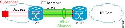
This section includes information about how the VLAN mapping and load balancing work. Figure 1 illustrates the traffic flow for the VLAN-to-port channel mapping.
Figure 1 VLAN-to-Port Channel Mapping
The black lines represent the physical interfaces connecting the MCP router with the L2 Switch. These are 1 GigabitEthernet interfaces but, in general, could be any Ethernet interfaces. These interfaces are bundled together in port-channels, shown in green.
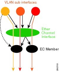
Figure 2 Mapping of VLAN to Member Links
Subscriber VLAN sub-interfaces, shown in shades of orange and red, are configured as L3 interfaces on top of the ether-channel interfaces. Mapping of the VLAN to the member-link (shown with the dotted black arrow) is done through configuration and downloaded in the dataplane so that outgoing VLAN traffic (shown with orange and red arrows) is sent over the associated active primary or secondary member-link. It is important to mention that the QoS configuration in this model is applied at the VLAN sub-interface and member link interface level implying that QoS queues are created at both levels.
VLAN-to-Port Channel Member Link Mapping
For port-channel traffic distribution, a member link has a configured state, primary or secondary, and an operational state, active or standby. The primary link is also active when the interface is up. If the primary interface is down, the interface is in primary standby state while the secondary interface is in secondary active state. If the primary link is up, the secondary link is in secondary standby, even if the interface is operationally up.
A primary and a secondary member link are each associated with each routed VLAN configured on a port channel main interface. If not all the conditions for per-VLAN traffic distribution are met, the mapping is not downloaded in the forwarding plane. Otherwise, the dataplane is updated with this mapping. When forwarding traffic for this VLAN, the primary interface is used as the outgoing interface when this interface is up, the secondary interface, if operational, is used when the primary interface is down.The VLAN to primary and secondary link association is configured manually as described in Configuration Examples for VLAN Mapping to Gigabit EtherChannel Member Links
The VLAN to primary and secondary link mapping can be done by the user, by the system or it can be a combination.
Table 1 describes the primary and secondary link configuration status and the resulting function of each configuration.
Table 1 VLAN Primary and Secondary Link Mapping Status
Note
Once the (VLAN, primary, secondary) association is performed (either through CLI, defaults or combination), the system validates the mapping and downloads it to the dataplane.
If there are no VLANs configured, all traffic forwarded over the port channel is dropped.
Adding Channel Member Links
When a new member link is added, new buckets are created and downloaded in the dataplane. For all VLANs that have this interface as either primary or secondary new VLAN-to-bucket mappings are downloaded in the dataplane. For all VLANs that need a default for primary and secondary, the default selection algorithm is triggered and if QoS validation passes, the VLAN-to-bucket mappings are downloaded. QoS policies create VLAN queues on the newly added link.
Deleting Member Links
When a member link is removed, a warning message is displayed. The VLAN queues from the link that is about to be deleted, VLAN-to-bucket mappings are removed and all affected buckets are removed.
EC Link Down Notification
When a link goes down, all the traffic for the VLANs that have this link assigned as primary have to be switched to the links that are designated as secondary if the secondary is up. The traffic for the VLANs that have this link assigned as secondary is not affected. The EC Link Down notification causes all buckets associated with a primary-secondary pair where primary is the down link and where secondary is up, are updated with the secondary link. The change is communicated to the dataplane.
All buckets associated with a primary-secondary pair where secondary is the down link and where primary is down, are updated so that the primary is now the active link. The change is communicated to the dataplane.
EC Link Up Notification
When a link goes up, all the traffic for the VLANs that have this link assigned as primary is switched to this link. The traffic for the VLANs that have this link assigned as secondary is not affected. The EC Link Up notification causes all buckets associated with a primary-secondary pair where primary is the link that came up and where secondary is up, are notified that the primary is up. The change is communicated to the dataplane.
All buckets associated with a primary-secondary pair where secondary is the link that went up and where primary is down, are notified that the secondary is now the primary link. The change is communicated to the dataplane.
How to Configure VLAN Mapping to GEC Links
This section includes configuration guidelines for setting up the VLAN mapping for GEC links and load balancing the links for uninterrupted traffic flow. To perform VLAN-based load balancing, the router has to be configured with the mapping of the VLAN-to-member link. Use the configuration guidelines in this section to configure VLAN port-channel linking and to enable VLAN load balancing on port channels.
Configuring VLAN-Based Manual Load Balancing
When load balancing is configured for GEC links, traffic flows are mapped to different buckets as dictated by the load balancing algorithm. The etherchannel module decides how buckets are distributed across member links.
For each Etherchannel configured, a set of 16 buckets are created. Each bucket has an active link associated with it that represents the interface to be used for all flows that are mapped to the same bucket.
All packets to be forwarded over the same VLAN sub-interface are considered to be part of the same flow that is mapped to one bucket. Each bucket is associated with a primary-secondary pair, and the buckets point to the active interface in the pair. Only one of the pair is active at a time. Multiple VLAN flows can be mapped to the same bucket if their (primary, secondary) mapping is the same.
The buckets are created when VLAN manual load balancing is enabled. When the globlal VLAN load balancing command is removed, the buckets are deleted.
Prerequisites
For VLAN load balancing over the port channel links to take effect
•
•
•
•
•
Associating a Primary and Secondary Link with a VLAN
Associating a primary and secondary link with a VLAN may be done in the following ways. If all of the following conditions are met, the load balancing information is downloaded in forwarding plane. If at any point after this, any of the conditions above is not met, the load balancing information is removed from the forwarding plane.
•
•
•
•
The primary and secondary options are available only if VLAN manual load balancing is enabled.
If the interfaces specified as primary or secondary are not configured as part of the port channel, or if the global VLAN load balancing is not enabled, warning messages are issued.
Warning: VLAN 500's main interface is not the channel group of primary=FastEthernet4/0Per-VLAN manual load-balancing will not take effect until channel-group is configured under the primary interface.Warning: VLAN 500's main interface is not the channel group of secondary=FastEthernet1/0Per-VLAN manual load-balancing will not take effect until channel-group is configured under the primary interface.SUMMARY STEPS
1.
2.
3.
4.
5.
6.
7.
8.
9.
10.
DETAILED STEPS
Troubleshooting Tips
The show etherchannel load-balance command can be used to display the port channel load balancing method currently in use.
The show interfaces port-channel [channel_id] etherchannel should be used to display the traffic distribution currently in use.
Disabling Load Balancing on the EtherChannel
To disable load balancing on the EtherChannle, use the [no | default] port-channel load-balance vlan-manual command. When this command is removed, a warning message is displayed if any VLAN subinterfaces exist:
Warning: Removing the Global VLAN LB command will affect traffic for all dot1Q VLANsRemoving a Member Link from the EtherChannel
To remove a member link from the EtherChannel, use the [no | default] channel group command
When a member link is removed from EC, if the link is included in a VLAN mapping, the following Warning is displayed:
Warning: Removing FastEthernet4/0 from the port-channel will affect traffic for the dot1Q
VLANs that include this link in their mapping.
Mapping for the Native VLAN (VLAN 1)
Default primary and secondary links are selected for the native VLAN if they are not configured.
Configuration Examples for VLAN Mapping to Gigabit EtherChannel Member Links
This section includes examples of configuration, for defining VLAN mapping and load balancing traffic on the EtherChannel links.VLAN Load Balancing Example
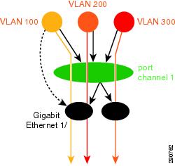
This example shows the load balancing configuration, including QoS features that might be applied to define policies for handling traffic. This example enables load balancing globally using the port-channel load-balance command. Note that IEEE 802.1Q encapsulation is configured on each port channel interface. Figure 3 illustrates the port channel bundle with the three VLANs used in this example.
Figure 3 Port Channel Bundle
enableconfigure terminalport-channel load-balance vlan-manualclass-map match-all BestEffort!class-map match-all video!class-map match-all voice!policy-map subscriberclass voicepriority level 1class videopriority level 2class class-default service-fragment BEshape average 10000bandwidth remaining percent 80policy-map aggregate-member-linkclass BestEffort service-fragment BEshape average 100000!interface Port-channel1ip address 172.1.2.3 255.255.0.0!interface Port-channel1.100encapsulation dot1Q 100 primary GigabitEthernet1/1secondary GigabitEthernet1/2ip address 173.1.2.100 255.255.255.0service-policy output subscriber!interface Port-channel1.200encapsulation dot1Q 200 primary GigabitEthernet1/2ip address 173.1.2.200 255.255.255.0service-policy output subscriber!interface Port-channel1.300encapsulation dot1Q 300ip address 173.1.2.300 255.255.255.0service-policy output subscriber!interface GigabitEthernet1/1no ip addresschannel-group 1 mode onservice-policy output aggregate-member-link!interface GigabitEthernet1/2no ip addresschannel-group 1 mode onservice-policy output aggregate-member-linkTroubleshooting Examples
Example1:
Router# show etherchannel load-balanceEtherChannel Load-Balancing Configuration:vlan-manualExample2:
Router#show etherchannel load-balanceEtherChannel Load-Balancing Configuration: not configuredUse the show interfaces port-channel command to display the traffic distribution currently in use.
Router# show interfaces port-channel 1 etherchannelActive Member List contains 0 interfacesPassive Member List contains 2 interfacesPort: FastEthernet4/0VLAN 1 (Pri, Ac, D, P) VLAN 100 (Pri, Ac, C, P) VLAN 200 (Sec, St, C, P)Port: FastEthernet1/0VLAN 1 (Sec, St, D, P) VLAN 100 (Sec, St, C, P) VLAN 200 (Pri, Ac, C, P)Bucket Information for VLAN Manual LB:Bucket 0 (p=FastEthernet4/0, s=FastEthernet4/0) active FastEthernet4/0Bucket 1 (p=FastEthernet4/0, s=FastEthernet1/0) active FastEthernet4/0Bucket 4 (p=FastEthernet1/0, s=FastEthernet4/0) active FastEthernet1/0Bucket 5 (p=FastEthernet1/0, s=FastEthernet1/0) active FastEthernet1/0To see the mapping of a VLAN to the primary and secondary links use the show vlans command.
Router# show vlans 100VLAN ID: 100 (IEEE 802.1Q Encapsulation)Protocols Configured: Received: Transmitted:VLAN trunk interfaces for VLAN ID 100:Port-channel1.1 (100)Mapping for traffic load-balancing using bucket 1:primary = FastEthernet4/0 (active, C, P)secondary = FastEthernet1/0 (standby, C, P)Total 0 packets, 0 bytes inputTotal 0 packets, 0 bytes outputNo subinterface configured with ISL VLAN ID 100Additional References
The following sections provide references related to the VLAN Mapping to Gigabit EtherChannel Links feature.
Related Documents
Standards
MIBs
•
To locate and download MIBs for selected platforms, Cisco IOS releases, and feature sets, use Cisco MIB Locator found at the following URL:
RFCs
Technical Assistance
Any Internet Protocol (IP) addresses used in this document are not intended to be actual addresses. Any examples, command display output, and figures included in the document are shown for illustrative purposes only. Any use of actual IP addresses in illustrative content is unintentional and coincidental.
© 2007, 2008 Cisco Systems, Inc. All rights reserved.