Feedback
Table Of Contents
Configuring Multicast VPN Inter-AS Support
Prerequisites for Configuring Multicast VPN Inter-AS Support
Restrictions for Configuring Multicast VPN Inter-AS Support
Information About Multicast VPN Inter-AS Support
MVPN Inter-AS Support Overview
Benefits of MVPN Inter-AS Support
MVPN Inter-AS Support Implementation Requirements
MVPN Inter-AS Support for Option A
MVPN Inter-AS Support Solution for Options B and C
BGP MDT SAFI Updates for MVPN Inter-AS Support
MDT Address Family in BGP for Multicast VPN Inter-AS Support
Guidelines for Configuring MDT Address Family Sessions on PE Routers for MVPN Inter-AS Support
MVPN Inter-AS MDT Establishment for Option B
MVPN Inter-AS MDT Establishment for Option C
How to Configure Multicast VPN Inter-AS Support
Configuring the MDT Address Family in BGP for Multicast VPN Inter-AS Support
Displaying Information about IPv4 MDT Sessions in BGP
Clearing IPv4 MDT Peering Sessions in BGP
Verifying the Establishment of Inter-AS MDTs in Option B and Option C Deployments
Configuration Examples for Multicast VPN Inter-AS Support
Configuring an IPv4 MDT Address-Family Session for Multicast VPN Inter-AS Support: Example
Configuring Back-to-Back ASBR PEs (Option A): Example
Configuring the Exchange of VPNv4 Routes Directly Between ASBRs (Option B): Example
Feature Information for Configuring Multicast VPN Inter-AS Support
Configuring Multicast VPN Inter-AS Support
First Published: November 8, 2004Last Updated: July 30, 2010The Multicast VPN Inter-AS Support feature enables Multicast Distribution Trees (MDTs) used for Multicast VPNs (MVPNs) to span multiple autonomous systems. Benefits include increased multicast coverage to customers that require multicast to span multiple service providers in a Multiprotocol Label Switching (MPLS) Layer 3 Virtual Private Network (VPN) service with the flexibility to support all options described in RFC 4364. Additionally, the Multicast VPN Inter-AS Support feature can be used to consolidate an existing MVPN service with another MVPN service, such as the case with a company merger or acquisition.
Finding Feature Information in This Module
Your Cisco IOS software release may not support all of the features documented in this module. For the latest feature information and caveats, see the release notes for your platform and software release. To reach links to specific feature documentation in this module and to see a list of the releases in which each feature is supported, use the "Feature Information for Configuring Multicast VPN Inter-AS Support" section.
Finding Support Information for Platforms and Cisco IOS and Catalyst OS Software Images
Use Cisco Feature Navigator to find information about platform support and Cisco IOS and Catalyst OS software image support. To access Cisco Feature Navigator, go to http://www.cisco.com/go/cfn. An account on Cisco.com is not required.
Contents
•
Prerequisites for Configuring Multicast VPN Inter-AS Support
•
•
•
•
•
Prerequisites for Configuring Multicast VPN Inter-AS Support
•
•
•
•
Restrictions for Configuring Multicast VPN Inter-AS Support
The Multicast VPN Inter-AS Support feature requires that all routers in the core be configured for Protocol Independent Multicast (PIM) Source Specific Multicast (SSM). Protocol Independent Multicast sparse mode (PIM-SM) and bidirectional PIM (bidir-PIM) are not supported.
Information About Multicast VPN Inter-AS Support
To configure the Multicast VPN Inter-AS Support feature, you should understand the following concepts:
•
•
•
•
•
•
MVPN Inter-AS Support Overview
As a general concept, MVPN inter-AS support enables service providers to provide multicast connectivity to VPN sites that span multiple autonomous systems. There are two types of MVPN inter-AS deployment scenarios:
•
•
The extensions added to support the Multicast VPN Inter-AS Support feature enable MDTs used for MVPNs to span multiple autonomous systems.
Benefits of MVPN Inter-AS Support
The MVPN Inter-AS Support feature provides the following benefits to service providers:
•
•
MVPN Inter-AS Support Implementation Requirements
The Multicast VPN Inter-AS Support feature was implemented in the Cisco IOS software in accordance to the following requirements:
•
–
The Option A model assumes direct connectivity between PE routers of different autonomous systems. The PE routers are attached by multiple physical or logical interfaces, each of which is associated with a given VPN (through a VRF instance). Each PE router, therefore, treats the adjacent PE router like a customer edge (CE) router, and the standard Layer 3 MPLS VPN mechanisms are used for route redistribution with each autonomous system; that is, the PEs use exterior BGP (eBGP) to distribute unlabeled IPv4 addresses to each other.
Note
–
In the Option B model, the PE routers use interior BGP (iBGP) to redistribute labeled VPNv4 routes either to an ASBR or to a route reflector of which an ASBR is a client. ASBRs then use multiprotocol eBGP (MP-eBGP) to advertise VPNv4 routes into the local autonomous system.
MP-eBGP provides the functionality to advertise VPNv4 prefix and label information across the service provider boundaries. The advertising ASBR router replaces the two-level label stack (which it uses to reach the originating PE router and VPN destination in the local autonomous system) with a locally allocated label before advertising the VPNv4 route. This replacement is necessary because the next-hop attribute of all routes advertised between the two service providers is reset to the ASBR router's peering address, so the ASBR router becomes the termination point of the label-switched path (LSP) for the advertised routes. To preserve the LSP between ingress and egress PE routers, the ASBR router must allocate a local label that may be used to identify the label stack of the route within the local VPN network. This newly allocated label is set on packets sent towards the prefix from the adjacent service provider.
Note
–
The Option C model combines MP-eBGP exchange of VPNv4 routes between route reflectors (RRs) of different autonomous systems with the next hops for these routes exchanged between corresponding ASBR routers. In the Option C model, VPNv4 routes are neither maintained nor distributed by the ASBRs. ASBRs must maintain labeled IPv4 /32 routes to the PE routers within its autonomous system and use eBGP to distribute these routes to other autonomous systems. ASBRs in any transit autonomous systems will also have to use eBGP to pass along the labeled /32 routes. The result is the creation of a LSP from the ingress PE router to the egress PE router.
Because RRs of different autonomous systems will not be directly connected, multihop functionality is required to allow for the establishment of the MP-eBGP peering sessions. The exchange of next hops is necessary because the RRs do not reset the next-hop attribute of the VPNv4 routes when advertising them to adjacent autonomous systems because they do not want to attract the traffic for the destinations that they advertise. They are not the original endpoint—just a relay station between the source and receiver PEs. The PE router next-hop addresses for the VPNv4 routes, thus, are exchanged between ASBR routers. The exchange of these addresses between autonomous systems can be accomplished by redistributing the PE router /32 addresses between the autonomous systems or by using BGP label distribution.
Note
•
Limitations That Prevented Option B and Option C Support Prior to the Introduction of Multicast VPN Inter-AS Support
Prior to the extensions introduced in association with the Multicast VPN Inter-AS Support feature, limitations existed that prevented MVPN inter-AS support for Option B and Option C. These limitations were related to the following areas:
•
–
–
Note
•
–
MVPN Inter-AS Support for Option A
The limitations that prevented support for MVPN inter-AS support Options B and C have never applied to Option A for the following reasons:
•
•
Note
MVPN Inter-AS Support Solution for Options B and C
The following extensions introduced in association with MVPN Inter-AS Support feature resolve the MVPN inter-AS protocol limitations related to supporting RPF and inter-AS MDTs in Option B and C deployments:
•
•
•
BGP Connector Attribute
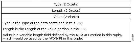
In an adjacent autonomous system, a PE router that wants to join a particular source of the default MDT for a given MVPN must know the originator's address of the source PE router. This presents some challenges for Option B inter-AS deployments because the originator next hop for VPNv4 routes is rewritten at one or more points in the network. To solve this limitation, each VPNv4 route must carry a new attribute (the BGP connector attribute) that defines the route's originator.
The BGP connector attribute is a transitive attribute that stores the PE router which originated a VPNv4 prefix. In a local autonomous system, the BGP connector attribute is the same as the next hop attribute. When advertised to other ASBRs in VPNv4 advertisements (as is the case in Option B), the value of the BGP connector attribute is preserved even after the next hop attribute is rewritten by ASBRs. The BGP connector attribute is a critical component of the MVPN inter-AS solution, helping to enable RPF to sources in remote autonomous systems.
Note
The format of the BGP connector attribute is shown in Figure 1.
Figure 1 BGP Connector Attribute
BGP MDT SAFI Updates for MVPN Inter-AS Support
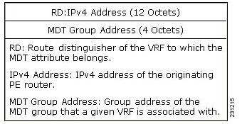
The BGP MDT SAFI is specifically designed to carry the address of the source PE router to which a PIM join should be sent for the MDT group contained in the PIM join. The format of the Network Layer Reachability Information (NLRI) carried in this SAFI is {RD:PE-IP-address}. The BGP MDT SAFI is capable of being advertised across autonomous system boundaries. Each MDT group is carried in the MP_REACH attribute using the format shown in Figure 2.
Figure 2 MDT SAFI Format
When RRs and MP-eBGP peerings are used, the advertisement of the BGP MDT SAFI is independent of the advertisement of VPNv4 routes. BGP MDT SAFI advertisements, however, are processed and filtered like VPNv4 advertisements.
ASBRs store the path advertised in BGP MDT SAFI updates in a separate table. How the BGP MDT SAFI is advertised determines the RPF path to the PE router that originated the advertisement.
PEs also store the BGP MDT SAFI update in a separate table. PE routers use the information contained in the BGP MDT SAFI to determine the ASBR that is the exit router to the source PE router in a adjacent autonomous system.
PIM RPF Vector
Normally, in an MVPN environment, PIM sends join messages containing the IP address of upstream PE routers that are sources of a given MDT group. To be able to perform RPF checks, however, P routers must have IPv4 reachability to source PE routers in remote autonomous systems. This behavior is not the case with inter-AS Options B and C because the autonomous systems do not exchange any of their IGP routes, including those of their local PE routers. However, P routers do have reachability to the BGP next hop of the BGP MDT update received with the BGP MDT SAFI updates at the PE routers. Therefore, if the PE routers add the remote PE router IP address (as received within the BGP MDT SAFI) and the BGP next-hop address of this address within the PIM join, the P routers can perform an RPF check on the BGP next-hop address rather than the original PE router address, which, in turn, allows the P router to forward the join toward the ASBR that injected the MDT SAFI updates for a remote autonomous system. This functionality is generally referred to as the PIM RPF Vector; the actual vector that is inserted into PIM joins is referred to as the RPF Vector or the Proxy Vector. The PIM RPF Vector, therefore, enables P routers to determine the exit ASBR to a source PE router in a remote autonomous system. Having received the join that contains a RPF Vector, an ASBR can then determine that the next-hop address is in fact itself and can perform an RPF check based on the originating PE router address carried in the PIM join.
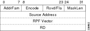
When configured on PE routers using the ip multicast rpf proxy vector command, the RPF Vector is encoded as a part of the source address in PIM join and prune messages. The RPF Vector is the IGP next hop for PIM RPF neighbor in PIM join and prune messages, which is typically the exit ASBR router to a prefix in a remote autonomous system.
The format of this PIM RPF Vector encoding in PIM join and prune messages is shown in Figure 3.
Figure 3 PIM RPF Vector Encoded in PIM Join and Prune Messages
Note
Originators of an RPF Vector
Whether or not a PE router originates an RPF Vector is determined by configuration; that is, the ip multicast rpf proxy vector command must be configured on all PE routers in order for an RPF Vector to be originated. The PE router that originates an RPF Vector always performs an RPF lookup on the source. When a PE router performs an RPF lookup on a source, the PE router learns the origin of an RPF Vector in one of the following ways:
•
•
Note
Note
Recipients of an RPF Vector
When a router receives a PIM join that contains an RPF Vector, that router stores the RPF Vector so that it can generate a PIM join to the exit ASBR router. P routers, thus, learn the RPF Vector from PIM joins. The RPF Vector is advertised to all P routers in the core. If multiple RPF Vectors are received by a router, the RPF Vector with the lower originator address is used. When the RPF Vector is present, it takes priority; as a result, RPF checks are triggered periodically to readvertise RPF Vectors upstream. If a router receives an RPF Vector that references a local interface (typically an ASBR), the RPF Vector is discarded and a normal RPF lookup is performed.
ASBR Receipt of an RPF Vector
When an ASBR receives an RPF Vector, it typically references a local interface (most likely a loopback interface); in which case, the RPF Vector is discarded and a normal RPF lookup is performed. If the RD type is 2, the ASBR performs an RPF lookup in the BGP MDT table that is built from the BGP MDT SAFI updates; this type of RPF lookup uses both the RD and the source PE address contained in the PIM join.
Interoperability with RPF Vector
A new PIM hello option is introduced along with the PIM RPF Vector extension to determine if the upstream router is capable of parsing the new encoding. An RPF Vector is only included in PIM messages when all PIM neighbors on an RPF interface support it.
MDT Address Family in BGP for Multicast VPN Inter-AS Support
The mdt keyword has been added to the address-family ipv4 command to configure an MDT address-family session.
Supported Policy
The following policy configuration parameters are supported under the BGP MDT SAFI:
•
•
Guidelines for Configuring MDT Address Family Sessions on PE Routers for MVPN Inter-AS Support
When configuring routers for MVPN inter-AS support, follow these guidelines:
•
•
•
MVPN Inter-AS MDT Establishment for Option B
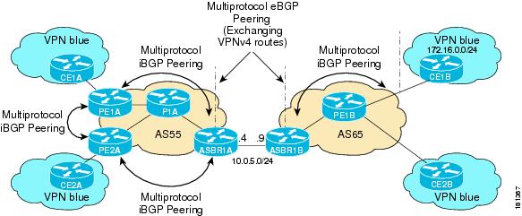
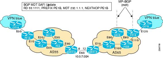
This section describes the sequence of events that leads to the establishment of an inter-AS MDT between the autonomous systems in the sample inter-AS Option B topology illustrated in Figure 4. For this topology, assume that all the routers have been configured properly to support all extensions associated with the Multicast VPN Inter-AS Support feature.
Figure 4 MVPN Inter-AS Support Option B Sample Topology
The following sequence of events occur to establish an MDT default tree rooted at PE1B in this inter-AS MVPN Option B topology:
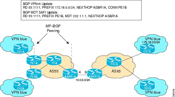
1.
Figure 5 BGP Updates from PE1B to ASBR1B
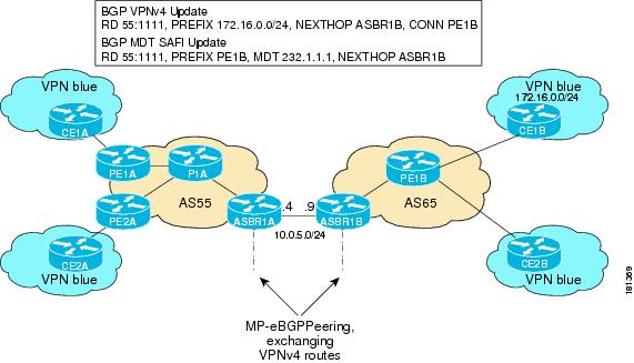
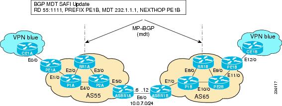
2.
Figure 6 BGP Updates from ASBR1B to ASBR1A
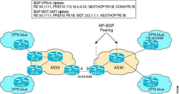
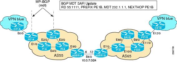
3.
Figure 7 BGP Updates from ASBR1A to PE1A
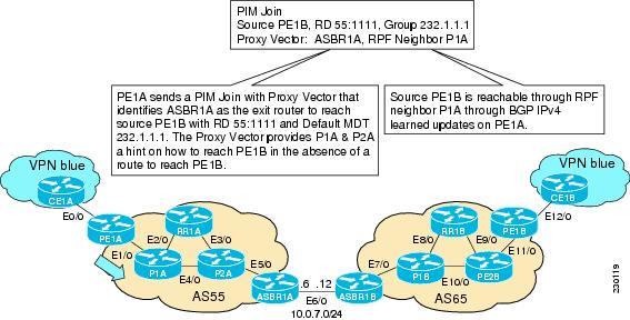
4.
Figure 8 SSM Default PIM Join from PE1A to P1A
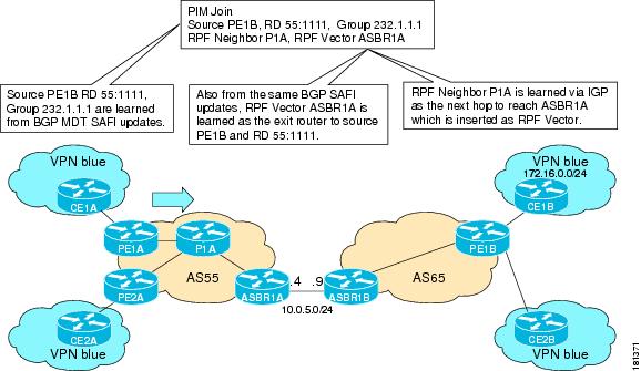
5.
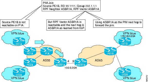
Figure 9 SSM Default MDT PIM Join from P1A to ASBR1A
6.
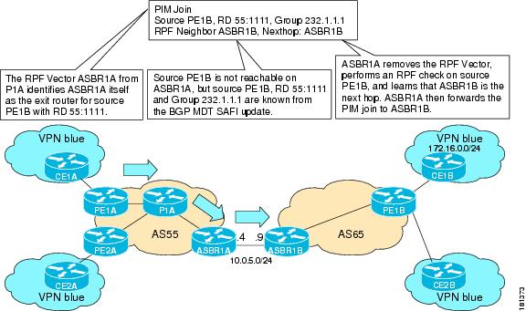
Figure 10 SSM Default MDT PIM Join from ASBR1A to ASBR1B
7.
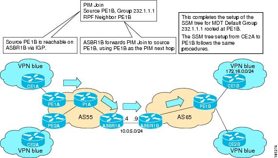
Figure 11 SSM Default MDT PIM Join from ASBR1B to PE1B
MVPN Inter-AS MDT Establishment for Option C
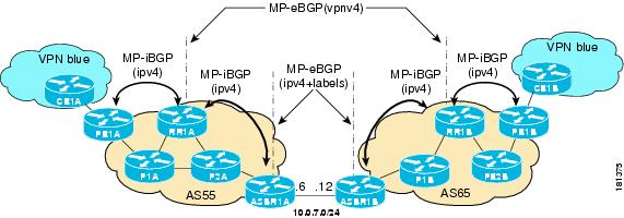
This section describes the sequence of events that leads to the establishment of an inter-AS MDT between the autonomous systems in the sample inter-AS Option C topology illustrated in Figure 12. For this topology, assume that all the routers have been configured properly to support all features associated with the Multicast VPN Inter-AS Support feature.
Figure 12 MVPN Inter-AS Support Option C Sample Topology
The following sequence of events occur to establish an MDT default tree rooted at PE1B in this inter-AS MVPN Option C topology:
1.
Figure 13 BGP MDT SAFI Update from PE1B to RR1B
2.
Figure 14 BGP MDT SAFI Update from RR1B to RR1A
3.
Figure 15 BGP MDT SAFI Update from RR1A to PE1A
4.
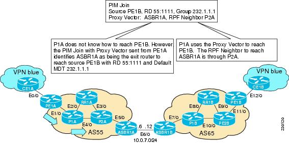
Figure 16 PIM SSM Join for Default MDT with Proxy Vector from PE1A to P1A
5.
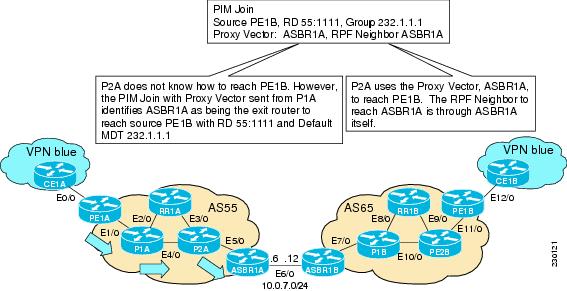
Figure 17 PIM SSM Join for Default MDT with Proxy Vector from P1A to P2A
6.
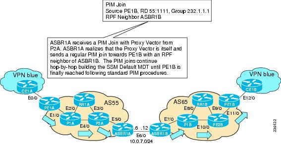
Figure 18 PIM SSM Join for Default MDT with Proxy Vector from P2A to ASBR1A
7.
Figure 19 PIM SSM Join for Default MDT with Proxy Vector from ASBR1A to PE1B
How to Configure Multicast VPN Inter-AS Support
This section contains the following tasks:
•
•
•
•
Configuring the MDT Address Family in BGP for Multicast VPN Inter-AS Support
Perform this task to configure an MDT address family session on PE routers to to establish MDT peering sessions for MVPN. The mdt keyword has been added to the address-family ipv4 command to configure an MDT address-family session.
Prerequisites
Before inter-AS VPN peering can be established through an MDT address family, MPLS and Cisco Express Forwarding (CEF) must be configured in the BGP network and multiprotocol BGP on PE routers that provide VPN services to CE routers.
Restrictions
The following policy configuration parameters are not supported:
•
•
•
SUMMARY STEPS
1.
2.
3.
4.
5.
6.
DETAILED STEPS
Displaying Information about IPv4 MDT Sessions in BGP
Perform this optional task to display information about IPv4 MDT sessions in BGP.
SUMMARY STEPS
1.
2.
DETAILED STEPS
Step 1
Use this command to enable privileged EXEC mode.
•
Router> enableStep 2
Use this command to display IPv4 MDT sessions in the IPv4 BGP routing table.
The following is sample output from the show ip bgp ipv4 mdt command with the all keyword:
Router# show ip bgp ipv4 mdt allBGP table version is 2, local router ID is 10.1.0.2Status codes: s suppressed, d damped, h history, * valid, > best, i - internal,r RIB-failure, S StaleOrigin codes: i - IGP, e - EGP, ? - incompleteNetwork Next Hop Metric LocPrf Weight PathRoute Distinguisher: 55:1111 (default for vrf blue)*> 10.5.5.5/32 10.1.0.1 55 0 23 24 25 54 ?* 10.9.9.9/32 0.0.0.0 0 ?
Clearing IPv4 MDT Peering Sessions in BGP
Perform this optional task to reset IPv4 MDT address-family sessions using the mdt keyword in one of the various forms of the clear ip bgp command. Due to the complexity of some of the keywords available for the clear ip bgp command, some of the keywords are documented as separate commands.
SUMMARY STEPS
1.
2.
DETAILED STEPS
Configuring a PE Router to Send BGP MDT Updates to Build the Default MDT for MVPN Inter-AS Support (Option B)
Perform this task to configure PE routers in an Option B deployment to support the extensions necessary (BGP connector attribute, BGP MDT SAFI, and RPF Vector) to send BGP MDT updates to build the default MDT for MVPN inter-AS support.
SUMMARY STEPS
1.
2.
3.
4.
5.
6.
7.
8.
9.
10.
11.
12.
13.
DETAILED STEPS
Configuring a PE Router to Send BGP MDT Updates to Build the Default MDT for MVPN Inter-AS Support (Option C)
Perform this task to configure PE routers in an Option B deployment to support the extensions necessary (BGP connector attribute, BGP MDT SAFI, and RPF Vector) to send BGP MDT updates to build the default MDT for MVPN inter-AS support.
SUMMARY STEPS
1.
2.
3.
4.
5.
6.
7.
8.
9.
10.
11.
12.
13.
DETAILED STEPS
Verifying the Establishment of Inter-AS MDTs in Option B and Option C Deployments
Perform this optional task to verify the establishment of a Inter-AS MDTs in Option B and Option C MVPN inter-AS deployments.
Note
SUMMARY STEPS
1.
2.
3.
4.
5.
DETAILED STEPS
Step 1
Use this command to enable privileged EXEC mode.
•
Router> enableStep 2
Use this command to display information about RPF Vectors received on a multicast router.
•
The following is sample output from the show ip mroute proxy command:
Router# show ip mroute proxy(192.168.0.8, 232.1.1.1)Proxy Assigner Origin Uptime/Expire55:1111/192.168.0.4 10.0.3.1 PIM 00:03:29/00:02:0655:1111/192.168.0.4 10.0.3.2 PIM 00:17:47/00:02:06Step 3
Use this command to display the PIM neighbors discovered by PIMv1 router query messages or PIMv2 hello messages
•
The following is sample output from the show ip pim neighbor command:
Router# show ip pim neighborPIM Neighbor TableMode: B - Bidir Capable, DR - Designated Router, N - Default DR Priority,S - State Refresh CapableNeighbor Interface Uptime/Expires Ver DRAddress Prio/Mode10.0.0.1 GigabitEthernet10/2 00:01:29/00:01:15 v2 1 / S10.0.0.3 GigabitEthernet10/3 00:01:15/00:01:28 v2 1 / DR S PStep 4
Use this command to display information about how IP multicast routing does RPF.
The following is sample output from the show ip rpf command:
Router# show ip rpf 10.7.0.7 232.1.1.1 rd 55:1111RPF information for ? (10.7.0.7)RPF interface: GigabitEthernet2/2RPF neighbor: ? (10.0.1.3)RPF route/mask: 10.5.0.5/32RPF type: unicast (UNKNOWN)RPF recursion count: 0Doing distance-preferred lookups across tablesBGP lookup of 55:1111/10.7.0.7 next_hop: 10.5.0.5PROXY vector: 10.5.0.5Step 5
Use this command to display information about the BGP advertisement of RDs for the MDT default group.
The following is sample output from the show ip pim mdt bgp command:
Router# show ip pim mdt bgpMDT (Route Distinguisher + IPv4) Router ID Next HopMDT group 232.1.1.155:1111:192.168.0.2 192.168.0.2 192.168.0.255:1111:192.168.0.8 192.168.0.4 192.168.0.4
Configuration Examples for Multicast VPN Inter-AS Support
This section provides the following configuration examples:
•
•
•
Configuring an IPv4 MDT Address-Family Session for Multicast VPN Inter-AS Support: Example
The following examples shows how to configure a router to support IPv4 MDT address-family session with the BGP neighbor at 10.1.1.2:
router bgp 1address-family ipv4 mdtneighbor 10.1.1.2 activateConfiguring a PE Router to Send BGP MDT Updates to Build the Default MDT for MVPN Inter-AS Support (Option B): Example
The following example shows how to configure a PE router to support the extensions necessary (BGP connector attribute, BGP MDT SAFI, and RPF Vector) to send BGP MDT updates to build the default MDT for MVPN inter-AS support in an Option B deployment. Only the relevant configuration is shown in this example.
!ip multicast-routingip multicast-routing vrf blueip multicast vrf blue rpf proxy rd vector!...router bgp 55...!address-family ipv4 mdtneighbor 192.168.0.2 activateneighbor 192.168.0.2 next-hop-selfneighbor 192.168.0.4 activateneighbor 192.168.0.4 next-hop-selfexit-address-family!address-family vpnv4neighbor 192.168.0.2 activateneighbor 192.168.0.2 send-community extendedneighbor 192.168.0.4 activateneighbor 192.168.0.4 send-community extendedexit-address-family!...!ip pim ssm default!Configuring a PE Router to Send BGP MDT Updates to Build the Default MDT for MVPN Inter-AS Support (Option C): Example
The following example shows how to configure a PE router to support the extensions necessary (BGP connector attribute, BGP MDT SAFI, and RPF Vector) to send BGP MDT updates to build the default MDT for MVPN inter-AS support in an Option B deployment. Only the relevant configuration is shown in this example.
!ip multicast-routingip multicast-routing vrf blueip multicast rpf proxy vector!...!router bgp 65...!address-family ipv4neighbor 10.252.252.10 activateneighbor 10.252.252.10 send-labelno auto-summaryno synchronizationexit-address-family!address-family ipv4 mdtneighbor 10.252.252.10 activateneighbor 10.252.252.10 send-community extendedexit-address-family!address-family vpnv4neighbor 10.252.252.10 activateneighbor 10.252.252.10 send-community extendedexit-address-family!...!ip pim ssm default!Configuring Back-to-Back ASBR PEs (Option A): Example
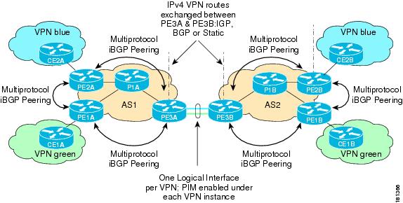
The following example shows how to configure support for MVPN inter-AS support Option A. This configuration example is based on the sample inter-AS network Option A topology illustrated in Figure 20.
In this configuration example, PE3A in AS1 is attached directly to PE3B in AS2. The two PE routers are attached by physical interfaces, one physical interface for each of the VPNs (VPN blue and VPN green) whose routes need to be passed from AS1 to AS2, and vice versa. Each PE will treat the other as if it were a CE router; that is, the PEs associate each interface with a VRF and use eBGP to distribute unlabeled IPv4 addresses to each other. Intermediate System-to-Intermediate System (IS-IS) is being used for the BGP peerings in both autonomous systems, and Routing Information Protocol (RIP) is being used on the PE routers that face the CE routers to dynamically learn the routes from the VRFs and advertise them as VPNv4 routes to the remote PE routers. RIP is also being used between the ASBRs to set up the eBGP peerings between PE3A and PE3B.
Note
Figure 20 Topology for MVPN Inter-AS Support Option A Configuration Example
Table 1 provides information about the topology used for the Option A configuration example presented in this section.
PE1A
!version 12.0service timestamps debug uptimeservice timestamps log uptimeno service password-encryption!hostname PE1A!boot-start-markerboot-end-marker!!ip subnet-zeroip cefno ip domain-lookupip vrf greenrd 55:2222route-target export 55:2222route-target import 55:2222mdt default 232.2.2.2!ip multicast-routingip multicast-routing vrf greenmpls label protocol ldp!!!interface Loopback0ip address 10.1.1.1 255.255.255.255no ip directed-broadcastip router isisip pim sparse-mode!interface Ethernet0/0ip vrf forwarding greenip address 172.25.11.1 255.255.255.0no ip directed-broadcastip pim sparse-modetag-switching ip!interface Ethernet1/0ip address 172.30.41.1 255.255.255.0no ip directed-broadcastip router isisip pim sparse-modetag-switching ip!router isisnet 49.0000.0000.1111.00!router ripversion 2!address-family ipv4 vrf greenversion 2network 172.25.0.0no auto-summaryexit-address-family!router bgp 1no synchronizationbgp log-neighbor-changesneighbor 10.1.1.2 remote-as 1neighbor 10.1.1.2 update-source Loopback0neighbor 10.1.1.3 remote-as 1neighbor 10.1.1.3 update-source Loopback0no auto-summary!address-family ipv4 mdtneighbor 10.1.1.2 activateneighbor 10.1.1.3 activateexit-address-family!address-family vpnv4neighbor 10.1.1.2 activateneighbor 10.1.1.2 send-community extendedneighbor 10.1.1.3 activateneighbor 10.1.1.3 send-community extendedexit-address-family!address-family ipv4 vrf greenredistribute rip metric 1no synchronizationexit-address-family!ip classless!ip pim ssm defaultip pim vrf green send-rp-announce Ethernet0/0 scope 32ip pim vrf green send-rp-discovery Ethernet0/0 scope 32ip pim vrf green register-rate-limit 2!!!control-plane!!line con 0line aux 0line vty 0 4login!no cns aaa enableendPE2A
!version 12.0service timestamps debug uptimeservice timestamps log uptimeno service password-encryption!hostname PE2A!boot-start-markerboot-end-marker!!ip subnet-zeroip cefno ip domain-lookupip vrf bluerd 55:1111route-target export 55:1111route-target import 55:1111mdt default 232.1.1.1!ip multicast-routingip multicast-routing vrf bluempls label protocol ldp!!!interface Loopback0ip address 10.1.1.2 255.255.255.255no ip directed-broadcastip router isisip pim sparse-mode!interface Ethernet0/0ip vrf forwarding blueip address 172.17.12.2 255.255.255.0no ip directed-broadcastip pim sparse-modetag-switching ip!interface Ethernet1/0no ip addressno ip directed-broadcastshutdown!interface Ethernet2/0ip address 172.19.142.2 255.255.255.0no ip directed-broadcastip router isisip pim sparse-modetag-switching ip!router isisnet 49.0000.0000.2222.00!router ripversion 2!address-family ipv4 vrf blueversion 2network 172.17.0.0no auto-summaryexit-address-family!router bgp 1no synchronizationbgp log-neighbor-changesneighbor 10.1.1.1 remote-as 1neighbor 10.1.1.1 update-source Loopback0neighbor 10.1.1.3 remote-as 1neighbor 10.1.1.3 update-source Loopback0no auto-summary!address-family ipv4 mdtneighbor 10.1.1.1 activateneighbor 10.1.1.3 activateexit-address-family!address-family vpnv4neighbor 10.1.1.1 activateneighbor 10.1.1.1 send-community extendedneighbor 10.1.1.3 activateneighbor 10.1.1.3 send-community extendedexit-address-family!address-family ipv4 vrf blueredistribute rip metric 1no synchronizationexit-address-family!ip classless!ip pim ssm defaultip pim vrf blue send-rp-announce Ethernet0/0 scope 32ip pim vrf blue send-rp-discovery Ethernet0/0 scope 32ip pim vrf blue ssm default!!!control-plane!!line con 0line aux 0line vty 0 4login!no cns aaa enableendPE3A
!version 12.0service timestamps debug uptimeservice timestamps log uptimeno service password-encryption!hostname PE3A!boot-start-markerboot-end-marker!!ip subnet-zeroip cefno ip domain-lookupip vrf bluerd 55:1111route-target export 55:1111route-target import 55:1111mdt default 232.1.1.1!ip vrf greenrd 55:2222route-target export 55:2222route-target import 55:2222mdt default 232.2.2.2!ip multicast-routingip multicast-routing vrf blueip multicast-routing vrf greenmpls label protocol ldp!!!interface Loopback0ip address 10.1.1.3 255.255.255.255no ip directed-broadcastip router isisip pim sparse-mode!interface Ethernet0/0no ip addressno ip directed-broadcastshutdown!interface Ethernet1/0no ip addressno ip directed-broadcastshutdown!interface Ethernet2/0no ip addressno ip directed-broadcastshutdown!interface Ethernet3/0ip address 192.168.143.3 255.255.255.0no ip directed-broadcastip router isisip pim sparse-modetag-switching ip!interface Ethernet4/0ip vrf forwarding blueip address 172.20.34.3 255.255.255.0no ip directed-broadcastip pim sparse-dense-modetag-switching ip!interface Ethernet5/0ip vrf forwarding greenip address 172.23.35.3 255.255.255.0no ip directed-broadcastip pim sparse-dense-modetag-switching ip!router eigrp 1!address-family ipv4 vrf bluenetwork 172.20.0.0no auto-summaryexit-address-family!router isisnet 49.0000.0000.3333.00!router ripversion 2!address-family ipv4 vrf greenversion 2redistribute bgp 1 metric 2network 172.23.0.0no auto-summaryexit-address-family!address-family ipv4 vrf blueversion 2redistribute bgp 1 metric 1network 172.20.0.0no auto-summaryexit-address-family!router bgp 1no synchronizationbgp log-neighbor-changesneighbor 10.1.1.1 remote-as 1neighbor 10.1.1.1 update-source Loopback0neighbor 10.1.1.2 remote-as 1neighbor 10.1.1.2 update-source Loopback0no auto-summary!address-family ipv4 mdtneighbor 10.1.1.1 activateneighbor 10.1.1.2 activateexit-address-family!address-family vpnv4neighbor 10.1.1.1 activateneighbor 10.1.1.1 send-community extendedneighbor 10.1.1.2 activateneighbor 10.1.1.2 send-community extendedbgp redistribute-internalexit-address-family!address-family ipv4 vrf greenno synchronizationbgp redistribute-internalexit-address-family!address-family ipv4 vrf blueredistribute ripno synchronizationbgp redistribute-internalexit-address-family!ip classless!ip pim ssm defaultip pim vrf blue ssm default!!!control-plane!!line con 0line aux 0line vty 0 4login!no cns aaa enableendPE3B
!version 12.0service timestamps debug uptimeservice timestamps log uptimeno service password-encryption!hostname PE3B!boot-start-markerboot-end-marker!!ip subnet-zeroip cefno ip domain-lookupip vrf bluerd 55:1111route-target export 55:1111route-target import 55:1111mdt default 232.1.1.1!ip vrf greenrd 55:2222route-target export 55:2222route-target import 55:2222mdt default 232.2.2.2!ip multicast-routingip multicast-routing vrf blueip multicast-routing vrf greenmpls label protocol ldp!!!interface Loopback0ip address 10.2.2.3 255.255.255.255no ip directed-broadcastip router isisip pim sparse-mode!interface Ethernet0/0no ip addressno ip directed-broadcastshutdown!interface Ethernet1/0no ip addressno ip directed-broadcastshutdown!interface Ethernet2/0no ip addressno ip directed-broadcastshutdown!interface Ethernet3/0ip address 172.16.43.3 255.255.255.0no ip directed-broadcastip router isisip pim sparse-modetag-switching ip!interface Ethernet4/0ip vrf forwarding blueip address 172.20.34.4 255.255.255.0no ip directed-broadcastip pim sparse-dense-modetag-switching ip!interface Ethernet5/0ip vrf forwarding greenip address 172.23.35.4 255.255.255.0no ip directed-broadcastip pim sparse-dense-modetag-switching ip!router isisnet 49.0000.0000.3333.00!router ripversion 2!address-family ipv4 vrf greenversion 2network 172.23.0.0no auto-summaryexit-address-family!address-family ipv4 vrf blueversion 2network 172.20.0.0no auto-summaryexit-address-family!router bgp 2no synchronizationbgp log-neighbor-changesredistribute rip metric 1neighbor 10.2.2.1 remote-as 2neighbor 10.2.2.1 update-source Loopback0neighbor 10.2.2.2 remote-as 2neighbor 10.2.2.2 update-source Loopback0no auto-summary!address-family ipv4 mdtneighbor 10.2.2.1 activateneighbor 10.2.2.2 activateexit-address-family!address-family vpnv4neighbor 10.2.2.1 activateneighbor 10.2.2.1 send-community extendedneighbor 10.2.2.2 activateneighbor 10.2.2.2 send-community extendedexit-address-family!address-family ipv4 vrf greenredistribute ripno synchronizationexit-address-family!address-family ipv4 vrf blueredistribute ripno synchronizationexit-address-family!ip classless!ip pim ssm defaultip pim vrf blue ssm default!!!control-plane!!line con 0line aux 0line vty 0 4login!no cns aaa enableendPE2B
!version 12.0service timestamps debug uptimeservice timestamps log uptimeno service password-encryption!hostname PE2B!boot-start-markerboot-end-marker!!ip subnet-zeroip cefno ip domain-lookupip vrf bluerd 55:1111route-target export 55:1111route-target import 55:1111mdt default 232.1.1.1!ip multicast-routingip multicast-routing vrf bluempls label protocol ldp!!!interface Loopback0ip address 10.2.2.2 255.255.255.255no ip directed-broadcastip router isisip pim sparse-mode!interface Ethernet0/0ip vrf forwarding blueip address 172.18.22.2 255.255.255.0no ip directed-broadcastip pim sparse-modetag-switching ip!interface Ethernet1/0no ip addressno ip directed-broadcastshutdown!interface Ethernet2/0ip address 172.19.42.2 255.255.255.0no ip directed-broadcastip router isisip pim sparse-modetag-switching ip!router isisnet 49.0000.0000.2222.00!router rip!address-family ipv4 vrf bluenetwork 172.18.0.0no auto-summaryexit-address-family!router bgp 2no synchronizationbgp log-neighbor-changesneighbor 10.2.2.1 remote-as 2neighbor 10.2.2.1 update-source Loopback0neighbor 10.2.2.3 remote-as 2neighbor 10.2.2.3 update-source Loopback0no auto-summary!address-family ipv4 mdtneighbor 10.2.2.1 activateneighbor 10.2.2.3 activateexit-address-family!address-family vpnv4neighbor 10.2.2.1 activateneighbor 10.2.2.1 send-community extendedneighbor 10.2.2.3 activateneighbor 10.2.2.3 send-community extendedexit-address-family!address-family ipv4 vrf blueno synchronizationexit-address-family!ip classless!ip pim ssm defaultip pim vrf blue ssm default!!!control-plane!!line con 0line aux 0line vty 0 4login!no cns aaa enableendPE1B
!version 12.0service timestamps debug uptimeservice timestamps log uptimeno service password-encryption!hostname PE1B!boot-start-markerboot-end-marker!!ip subnet-zeroip cefno ip domain-lookupip vrf greenrd 55:2222route-target export 55:2222route-target import 55:2222mdt default 232.2.2.2!ip multicast-routingip multicast-routing vrf greenmpls label protocol ldp!!!interface Loopback0ip address 10.2.2.1 255.255.255.255no ip directed-broadcastip router isisip pim sparse-mode!interface Ethernet0/0ip vrf forwarding greenip address 172.25.111.1 255.255.255.0no ip directed-broadcastip pim sparse-modetag-switching ip!interface Ethernet1/0ip address 172.30.141.1 255.255.255.0no ip directed-broadcastip router isisip pim sparse-modetag-switching ip!router isisnet 49.0000.0000.1111.00!router ripversion 2!address-family ipv4 vrf greenversion 2network 172.25.0.0no auto-summaryexit-address-family!router bgp 2no synchronizationbgp log-neighbor-changesneighbor 10.2.2.2 remote-as 2neighbor 10.2.2.2 update-source Loopback0neighbor 10.2.2.3 remote-as 2neighbor 10.2.2.3 update-source Loopback0no auto-summary!address-family ipv4 mdtneighbor 10.2.2.2 activateneighbor 10.2.2.3 activateexit-address-family!address-family vpnv4neighbor 10.2.2.2 activateneighbor 10.2.2.2 send-community extendedneighbor 10.2.2.3 activateneighbor 10.2.2.3 send-community extendedexit-address-family!address-family ipv4 vrf greenno synchronizationexit-address-family!ip classless!ip pim ssm default!!!control-plane!!line con 0line aux 0line vty 0 4login!no cns aaa enableendConfiguring the Exchange of VPNv4 Routes Directly Between ASBRs (Option B): Example
The following example shows how to configure MVPN inter-AS support in an Option B deployment. This configuration is based on the sample inter-AS topology illustrated in Figure 21.
In this configuration example, PE1A and PE2A are configured to use iBGP to redistribute labeled VPNv4 routes to each other and to ASBR1A, and PE1B is configured to redistribute labeled VPNv4 routes to ASBR1B. ASBR1A and ASBR1B are configured to use eBGP to exchange those labeled VPNv4 routes to each other.
Figure 21 Topology for MVPN Inter-AS Support Option B Configuration Example
Table 2 provides information about the topology used for this particular Option B configuration example.
PE1A
!ip vrf bluerd 55:1111mdt default 232.1.1.1!ip multicast-routingip multicast-routing vrf blueip multicast vrf blue rpf proxy rd vector!...!interface Ethernet0/0ip vrf forwarding blueip pim sparse-mode!...!router bgp 55no synchronizationbgp log-neighbor-changesneighbor 192.168.0.2 remote-as 55neighbor 192.168.0.2 update-source Loopback0neighbor 192.168.0.4 remote-as 55neighbor 192.168.0.4 update-source Loopback0no auto-summary!address-family ipv4 mdtneighbor 192.168.0.2 activateneighbor 192.168.0.2 next-hop-selfneighbor 192.168.0.4 activateneighbor 192.168.0.4 next-hop-selfexit-address-family!address-family vpnv4neighbor 192.168.0.2 activateneighbor 192.168.0.2 send-community extendedneighbor 192.168.0.4 activateneighbor 192.168.0.4 send-community extendedexit-address-family!address-family ipv4 vrf blueredistribute connectedredistribute staticredistribute rip metric 50no auto-summaryno synchronizationexit-address-family!...!ip pim ssm default!PE2A
!ip vrf bluerd 55:1111mdt default 232.1.1.1!ip multicast-routingip multicast-routing vrf blueip multicast vrf blue rpf proxy rd vector!...!interface Ethernet0/0ip vrf forwarding blueip pim sparse-mode!...!router bgp 55neighbor 192.168.0.1 remote-as 55neighbor 192.168.0.1 update-source Loopback0neighbor 192.168.0.4 remote-as 55neighbor 192.168.0.4 update-source Loopback0!address-family ipv4 mdtneighbor 192.168.0.1 activateneighbor 192.168.0.1 next-hop-selfneighbor 192.168.0.4 activateneighbor 192.168.0.4 next-hop-selfexit-address-family!address-family vpnv4neighbor 192.168.0.1 activateneighbor 192.168.0.1 send-community extendedneighbor 192.168.0.4 activateneighbor 192.168.0.4 send-community extendedexit-address-family!address-family ipv4 vrf blueredistribute connectedredistribute staticno synchronizationexit-address-family!...!ip pim ssm default!ASBR1A
!ip multicast-routingip multicast-routing vrf blue!...!!interface Ethernet0/0ip pim sparse-mode!...!router bgp 55bgp log-neighbor-changesneighbor 10.0.5.9 remote-as 65neighbor 192.168.0.1 remote-as 55neighbor 192.168.0.1 update-source Loopback0neighbor 192.168.0.2 remote-as 55neighbor 192.168.0.2 update-source Loopback0!address-family ipv4 mdtneighbor 10.0.5.9 activateneighbor 192.168.0.1 activateneighbor 192.168.0.1 next-hop-selfneighbor 192.168.0.2 activateneighbor 192.168.0.2 next-hop-selfexit-address-family!address-family vpnv4neighbor 10.0.5.9 activateneighbor 10.0.5.9 send-community extendedneighbor 192.168.0.1 activateneighbor 192.168.0.1 send-community extendedneighbor 192.168.0.1 next-hop-selfneighbor 192.168.0.2 activateneighbor 192.168.0.2 send-community extendedneighbor 192.168.0.2 next-hop-selfexit-address-family!...!ip pim ssm default!ASBR1B
!ip multicast-routingip multicast-routing vrf blue!...!interface Ethernet0/0ip pim sparse-mode!...!router bgp 65bgp log-neighbor-changesneighbor 10.0.5.4 remote-as 55neighbor 192.168.0.8 remote-as 65neighbor 192.168.0.8 update-source Loopback0!address-family ipv4 mdtneighbor 10.0.5.4 activateneighbor 192.168.0.8 activateneighbor 192.168.0.8 next-hop-selfexit-address-family!address-family vpnv4neighbor 10.0.5.4 activateneighbor 10.0.5.4 send-community extendedneighbor 192.168.0.8 activateneighbor 192.168.0.8 send-community extendedneighbor 192.168.0.8 next-hop-selfexit-address-family!...!ip pim ssm default!PE1B
!ip vrf bluerd 55:1111mdt default 232.1.1.1!ip multicast-routingip multicast-routing vrf blueip multicast vrf blue rpf proxy rd vector!...!interface Ethernet0/0ip vrf forwarding blueip pim sparse-mode!...!router bgp 65neighbor 192.168.0.9 remote-as 65neighbor 192.168.0.9 update-source Loopback0!address-family ipv4 mdtneighbor 192.168.0.9 activateneighbor 192.168.0.9 next-hop-selfexit-address-family!address-family vpnv4neighbor 192.168.0.9 activateneighbor 192.168.0.9 send-community extendedexit-address-family!address-family ipv4 vrf blueredistribute connectedredistribute staticredistribute rip metric 50no synchronizationexit-address-family!...!ip pim ssm default!The following is sample output from the show ip pim mdt bgp command for PE1A, PE2A, and PE1B. The sample output displays information about the BGP advertisement of RDs for the MDT default group 232.1.1.1. The output displays the MDT default groups advertised, the RDs and source addresses of sources sending to the MDT default groups, the BGP router ID of the advertising routers, and the BGP next hop address contained in the advertisements.
PE1A# show ip pim mdt bgpMDT (Route Distinguisher + IPv4) Router ID Next HopMDT group 232.1.1.155:1111:192.168.0.2 192.168.0.2 192.168.0.255:1111:192.168.0.8 192.168.0.4 192.168.0.4PE2A# show ip pim mdt bgpMDT (Route Distinguisher + IPv4) Router ID Next HopMDT group 232.1.1.155:1111:192.168.0.1 192.168.0.1 192.168.0.155:1111:192.168.0.8 192.168.0.4 192.168.0.4PE1B# show ip pim mdt bgpMDT (Route Distinguisher + IPv4) Router ID Next HopMDT group 232.1.1.155:1111:192.168.0.1 192.168.0.9 192.168.0.955:1111:192.168.0.2 192.168.0.9 192.168.0.9The following are sample outputs from the show ip mroute proxy command for PE1A, PE2A, and PE1B. The output displays information about the RPF Vectors learned by each PE router in this configuration example. The RPF Vector is the exit address of the ASBR router through which PIM messages are sent to reach inter-AS sources. The "Proxy" field displays the RPF Vectors learned by the PE routers. Each RPF Vector listed under the "Proxy" field is prepended by the RD associated with the RPF Vector. Because the PE routers are the assigners of the RPF Vector (that is, the PE routers insert the RPF Vector into PIM joins), 0.0.0.0 is the address displayed under the "Assigner" field in all the sample outputs. Finally, because PE routers learn the RPF Vector from BGP MDT SAFI updates, BGP MDT is displayed as the origin under the "Origin" field in all the outputs.
PE1A# show ip mroute proxy(192.168.0.8, 232.1.1.1)Proxy Assigner Origin Uptime/Expire55:1111/192.168.0.4 0.0.0.0 BGP MDT 00:13:07/stoppedPE2A# show ip mroute proxy(192.168.0.8, 232.1.1.1)Proxy Assigner Origin Uptime/Expire55:1111/192.168.0.4 0.0.0.0 BGP MDT 00:14:28/stoppedPE1B# show ip mroute proxy(192.168.0.1, 232.1.1.1)Proxy Assigner Origin Uptime/Expire55:1111/192.168.0.9 0.0.0.0 BGP MDT 00:35:19/stopped(192.168.0.2, 232.1.1.1)Proxy Assigner Origin Uptime/Expire55:1111/192.168.0.9 0.0.0.0 BGP MDT 00:35:49/stoppedThe following is sample output from the show ip mroute proxy command from P1A. Because P routers learn the RPF Vector from the PIM joins sent from PE routers, the IP addresses of PE1A (10.0.3.1) and PE2A (10.0.3.2) are displayed under the "Assigner" field in the output for P1A. Because P1A learns the RPF Vector from encodings in the PIM join message, PIM is displayed as the origin under the "Origin" field.
P1A# show ip mroute proxy(192.168.0.8, 232.1.1.1)Proxy Assigner Origin Uptime/Expire55:1111/192.168.0.4 10.0.3.1 PIM 00:03:29/00:02:0655:1111/192.168.0.4 10.0.3.2 PIM 00:17:47/00:02:06The following is sample output from the show ip mroute proxy command for ASBR1A and ASBR1B. If a router receives an RPF Vector that references a local interface (which occurs in an Option B deployment when an ASBR receives a RPF Vector owned by a local interface), the router discards the RPF Vector and performs a normal RPF lookup using information that the router learned from BGP MDT SAFI updates. In the output for all ASBR routers, under the "Proxy" field, the word "local" is displayed instead of the RPF Vector because ASBR1A and ASBR1B are using local interfaces to perform RPF lookups for PIM joins with RPF Vectors that reference one of their local interfaces. The "Assigner" field displays the RPF address that sent the PIM join to the ASBR. Because the ASBRs learn the RPF Vectors from the PIM joins (the RPF Vectors that are subsequently discarded), PIM is displayed as the origin under the "Origin" field.
ASBR1A# show ip mroute proxy(192.168.0.1, 232.1.1.1)Proxy Assigner Origin Uptime/Expire55:1111/local 10.0.5.9 PIM 00:18:19/00:02:46(192.168.0.2, 232.1.1.1)Proxy Assigner Origin Uptime/Expire55:1111/local 10.0.5.9 PIM 00:18:50/00:02:24(192.168.0.8, 232.1.1.1)Proxy Assigner Origin Uptime/Expire55:1111/local 10.0.4.3 PIM 00:18:49/00:02:19ASBR1B# show ip mroute proxy(192.168.0.1, 232.1.1.1)Proxy Assigner Origin Uptime/Expire55:1111/local 10.0.7.8 PIM 00:37:39/00:02:44(192.168.0.2, 232.1.1.1)Proxy Assigner Origin Uptime/Expire55:1111/local 10.0.7.8 PIM 00:38:10/00:02:19(192.168.0.8, 232.1.1.1)Proxy Assigner Origin Uptime/Expire55:1111/local 10.0.5.4 PIM 00:38:09/00:02:19The following is sample output from the show ip mroute command for PE1A, PE2A, P1A, ASBR1A, ASBR1B, and PE1B. The sample outputs show the global table for the MDT default group 232.1.1.1. The output from this command confirms that all three PE routers (PE1A, PE2A, and PE1B) have joined the default MDT.
PE1A
PE1A# show ip mroute 232.1.1.1IP Multicast Routing TableFlags: D - Dense, S - Sparse, B - Bidir Group, s - SSM Group, C - Connected,L - Local, P - Pruned, R - RP-bit set, F - Register flag,T - SPT-bit set, J - Join SPT, M - MSDP created entry,X - Proxy Join Timer Running, A - Candidate for MSDP Advertisement,U - URD, I - Received Source Specific Host Report,Z - Multicast Tunnel, z - MDT-data group sender,Y - Joined MDT-data group, y - Sending to MDT-data groupV - RD & Vector, v - VectorOutgoing interface flags: H - Hardware switched, A - Assert winnerTimers: Uptime/ExpiresInterface state: Interface, Next-Hop or VCD, State/Mode(192.168.0.8, 232.1.1.1), 00:13:11/00:02:41, flags: sTIZVIncoming interface: Ethernet2/0, RPF nbr 10.0.3.3, vector 192.168.0.4Outgoing interface list:MVRF blue, Forward/Sparse-Dense, 00:13:11/00:00:00(192.168.0.2, 232.1.1.1), 00:13:12/00:02:41, flags: sTIZIncoming interface: Ethernet2/0, RPF nbr 10.0.3.2Outgoing interface list:MVRF blue, Forward/Sparse-Dense, 00:13:12/00:00:00(192.168.0.1, 232.1.1.1), 00:13:12/00:03:27, flags: sTIncoming interface: Loopback0, RPF nbr 0.0.0.0Outgoing interface list:Ethernet2/0, Forward/Sparse-Dense, 00:13:11/00:02:50PE2A
PE2A# show ip mroute 232.1.1.1IP Multicast Routing TableFlags: D - Dense, S - Sparse, B - Bidir Group, s - SSM Group, C - Connected,L - Local, P - Pruned, R - RP-bit set, F - Register flag,T - SPT-bit set, J - Join SPT, M - MSDP created entry,X - Proxy Join Timer Running, A - Candidate for MSDP Advertisement,U - URD, I - Received Source Specific Host Report,Z - Multicast Tunnel, z - MDT-data group sender,Y - Joined MDT-data group, y - Sending to MDT-data groupV - RD & Vector, v - VectorOutgoing interface flags: H - Hardware switched, A - Assert winnerTimers: Uptime/ExpiresInterface state: Interface, Next-Hop or VCD, State/Mode(192.168.0.8, 232.1.1.1), 00:17:05/00:02:46, flags: sTIZVIncoming interface: Ethernet2/0, RPF nbr 10.0.3.3, vector 192.168.0.4Outgoing interface list:MVRF blue, Forward/Sparse-Dense, 00:17:05/00:00:00(192.168.0.1, 232.1.1.1), 00:17:05/00:02:46, flags: sTIZIncoming interface: Ethernet2/0, RPF nbr 10.0.3.1Outgoing interface list:MVRF blue, Forward/Sparse-Dense, 00:17:05/00:00:00(192.168.0.2, 232.1.1.1), 00:17:06/00:03:15, flags: sTIncoming interface: Loopback0, RPF nbr 0.0.0.0Outgoing interface list:Ethernet2/0, Forward/Sparse-Dense, 00:17:06/00:03:08P1A
P1A# show ip mroute 232.1.1.1IP Multicast Routing TableFlags: D - Dense, S - Sparse, B - Bidir Group, s - SSM Group, C - Connected,L - Local, P - Pruned, R - RP-bit set, F - Register flag,T - SPT-bit set, J - Join SPT, M - MSDP created entry,X - Proxy Join Timer Running, A - Candidate for MSDP Advertisement,U - URD, I - Received Source Specific Host Report,Z - Multicast Tunnel, z - MDT-data group sender,Y - Joined MDT-data group, y - Sending to MDT-data groupV - RD & Vector, v - VectorOutgoing interface flags: H - Hardware switched, A - Assert winnerTimers: Uptime/ExpiresInterface state: Interface, Next-Hop or VCD, State/Mode(192.168.0.1, 232.1.1.1), 00:17:43/00:03:08, flags: sTIncoming interface: Ethernet2/0, RPF nbr 10.0.3.1Outgoing interface list:Ethernet3/0, Forward/Sparse-Dense, 00:17:43/00:02:51(192.168.0.8, 232.1.1.1), 00:18:12/00:03:15, flags: sTVIncoming interface: Ethernet3/0, RPF nbr 10.0.4.4, vector 192.168.0.4Outgoing interface list:Ethernet2/0, Forward/Sparse-Dense, 00:18:12/00:03:15(192.168.0.2, 232.1.1.1), 00:18:13/00:03:18, flags: sTIncoming interface: Ethernet2/0, RPF nbr 10.0.3.2Outgoing interface list:Ethernet3/0, Forward/Sparse-Dense, 00:18:13/00:03:18ASBR1A
ASBR1A# show ip mroute 232.1.1.1IP Multicast Routing TableFlags: D - Dense, S - Sparse, B - Bidir Group, s - SSM Group, C - Connected,L - Local, P - Pruned, R - RP-bit set, F - Register flag,T - SPT-bit set, J - Join SPT, M - MSDP created entry,X - Proxy Join Timer Running, A - Candidate for MSDP Advertisement,U - URD, I - Received Source Specific Host Report,Z - Multicast Tunnel, z - MDT-data group sender,Y - Joined MDT-data group, y - Sending to MDT-data groupV - RD & Vector, v - VectorOutgoing interface flags: H - Hardware switched, A - Assert winnerTimers: Uptime/ExpiresInterface state: Interface, Next-Hop or VCD, State/Mode(10.254.254.8, 232.1.1.1), 00:20:13/00:03:16, flags: sTIncoming interface: Ethernet6/0, RPF nbr 10.0.7.12Outgoing interface list:Ethernet5/0, Forward/Sparse-Dense, 00:20:13/00:02:46(10.254.254.2, 232.1.1.1), 00:20:13/00:03:16, flags: sTIncoming interface: Ethernet5/0, RPF nbr 10.0.6.5Outgoing interface list:Ethernet6/0, Forward/Sparse-Dense, 00:20:13/00:02:39ASBR1B
ASBR1B# show ip mroute 232.1.1.1IP Multicast Routing TableFlags: D - Dense, S - Sparse, B - Bidir Group, s - SSM Group, C - Connected,L - Local, P - Pruned, R - RP-bit set, F - Register flag,T - SPT-bit set, J - Join SPT, M - MSDP created entry,X - Proxy Join Timer Running, A - Candidate for MSDP Advertisement,U - URD, I - Received Source Specific Host Report,Z - Multicast Tunnel, z - MDT-data group sender,Y - Joined MDT-data group, y - Sending to MDT-data groupV - RD & Vector, v - VectorOutgoing interface flags: H - Hardware switched, A - Assert winnerTimers: Uptime/ExpiresInterface state: Interface, Next-Hop or VCD, State/Mode(192.168.0.1, 232.1.1.1), 00:37:43/00:03:16, flags: sTVIncoming interface: Ethernet4/0, RPF nbr 10.0.5.4, vector 10.0.5.4Outgoing interface list:Ethernet6/0, Forward/Sparse-Dense, 00:37:43/00:03:10(192.168.0.8, 232.1.1.1), 00:38:14/00:03:16, flags: sTIncoming interface: Ethernet6/0, RPF nbr 10.0.7.8Outgoing interface list:Ethernet4/0, Forward/Sparse-Dense, 00:38:14/00:02:45(192.168.0.2, 232.1.1.1), 00:38:14/00:03:16, flags: sTVIncoming interface: Ethernet4/0, RPF nbr 10.0.5.4, vector 10.0.5.4Outgoing interface list:Ethernet6/0, Forward/Sparse-Dense, 00:38:14/00:02:45PE1B
PE1B# show ip mroute 232.1.1.1IP Multicast Routing TableFlags: D - Dense, S - Sparse, B - Bidir Group, s - SSM Group, C - Connected,L - Local, P - Pruned, R - RP-bit set, F - Register flag,T - SPT-bit set, J - Join SPT, M - MSDP created entry,X - Proxy Join Timer Running, A - Candidate for MSDP Advertisement,U - URD, I - Received Source Specific Host Report,Z - Multicast Tunnel, z - MDT-data group sender,Y - Joined MDT-data group, y - Sending to MDT-data groupV - RD & Vector, v - VectorOutgoing interface flags: H - Hardware switched, A - Assert winnerTimers: Uptime/ExpiresInterface state: Interface, Next-Hop or VCD, State/Mode(192.168.0.1, 232.1.1.1), 00:35:23/00:02:40, flags: sTIZVIncoming interface: Ethernet6/0, RPF nbr 10.0.7.9, vector 192.168.0.9Outgoing interface list:MVRF blue, Forward/Sparse-Dense, 00:35:23/00:00:00(192.168.0.2, 232.1.1.1), 00:35:53/00:02:40, flags: sTIZVIncoming interface: Ethernet6/0, RPF nbr 10.0.7.9, vector 192.168.0.9Outgoing interface list:MVRF blue, Forward/Sparse-Dense, 00:35:53/00:00:00(192.168.0.8, 232.1.1.1), 00:35:53/00:03:10, flags: sTIncoming interface: Loopback0, RPF nbr 0.0.0.0Outgoing interface list:Ethernet6/0, Forward/Sparse-Dense, 00:35:53/00:02:35Configuring the Exchange of VPNv4 Routes Between RRs Using Multihop MP-EBGP Peering Sessions (Option C): Example
The following example shows how to configure support for MVPN inter-AS option C. This configuration is based on the sample inter-AS topology illustrated in Figure 22.
In the configuration example, MP-eBGP is used to exchange VPNv4 routes between RRs of different autonomous systems with the next hops for these routes exchanged between corresponding ASBR routers. Because the RRs in the two autonomous systems are not directly connected, multihop functionality is required to allow them to establish MP-eBGP peering sessions. The PE router next-hop addresses for the VPNv4 routes are exchanged between ASBR routers. In this configuration example, the exchange of these addresses between autonomous systems is established using IPv4 BGP label distribution, which enables the ASBRs to distribute IPv4 routes with MPLS labels.
Figure 22 Topology for MVPN Inter-AS Support Option C Configuration Example
Table 3 provides information about the topology used for this inter-AS MVPN Option C configuration example.
PE1A
!ip vrf bluerd 55:1111mdt default 232.1.1.1!ip multicast-routingip multicast-routing vrf blueip multicast rpf proxy vector!...!interface Ethernet0/0ip vrf forwarding blueip pim sparse-mode!...!router bgp 55no bgp default route-target filterbgp log-neighbor-changesneighbor 10.252.252.4 remote-as 55neighbor 10.252.252.4 update-source Loopback0!address-family ipv4neighbor 10.252.252.4 activateneighbor 10.252.252.4 send-labelno auto-summaryno synchronizationexit-address-family!address-family ipv4 mdtneighbor 10.252.252.4 activateneighbor 10.252.252.4 send-community extendedexit-address-family!address-family vpnv4neighbor 10.252.252.4 activateneighbor 10.252.252.4 send-community extendedexit-address-family!address-family ipv4 vrf blueredistribute connectedredistribute staticredistribute rip metric 50no synchronizationexit-address-family!...!ip pim ssm default!RR1A
!router bgp 55neighbor 10.252.252.10 remote-as 65neighbor 10.252.252.10 ebgp-multihop 255neighbor 10.252.252.10 update-source Loopback0neighbor 10.254.254.2 remote-as 55neighbor 10.254.254.2 update-source Loopback0neighbor 10.254.254.6 remote-as 55neighbor 10.254.254.6 update-source Loopback0!address-family ipv4no neighbor 10.252.252.10 activateneighbor 10.254.254.2 activateneighbor 10.254.254.2 route-reflector-clientneighbor 10.254.254.2 send-labelneighbor 10.254.254.6 activateneighbor 10.254.254.6 route-reflector-clientneighbor 10.254.254.6 send-labelno auto-summaryno synchronizationexit-address-family!address-family ipv4 mdtneighbor 10.252.252.10 activateneighbor 10.252.252.10 next-hop-unchangedneighbor 10.254.254.2 activateexit-address-family!address-family vpnv4neighbor 10.252.252.10 activateneighbor 10.252.252.10 send-community extendedneighbor 10.252.252.10 next-hop-unchangedneighbor 10.254.254.2 activateneighbor 10.254.254.2 send-community extendedneighbor 10.254.254.2 route-reflector-clientexit-address-family!ASBR1A
!ip multicast-routingip multicast-routing vrf blue!...!interface Ethernet7/0ip vrf forwarding blueip pim sparse-mode!...!router bgp 55neighbor 10.0.7.12 remote-as 65neighbor 10.252.252.4 remote-as 55neighbor 10.252.252.4 update-source Loopback0!address-family ipv4redistribute isis level-2 route-map inter-asneighbor 10.0.7.12 activateneighbor 10.0.7.12 route-map IN inneighbor 10.0.7.12 route-map OUT outneighbor 10.0.7.12 send-labelneighbor 10.252.252.4 activateneighbor 10.252.252.4 next-hop-selfneighbor 10.252.252.4 send-labelno auto-summaryno synchronizationexit-address-family!...!ip pim ssm default!ASBR1B
!ip multicast-routingip multicast-routing vrf blue!...!interface Ethernet6/0ip vrf forwarding blueip pim sparse-mode!...!router bgp 65neighbor 10.0.7.6 remote-as 55neighbor 10.252.252.10 remote-as 65neighbor 10.252.252.10 update-source Loopback0!address-family ipv4redistribute isis level-2 route-map inter-asneighbor 10.0.7.6 activateneighbor 10.0.7.6 route-map IN inneighbor 10.0.7.6 route-map OUT outneighbor 10.0.7.6 send-labelneighbor 10.252.252.10 activateneighbor 10.252.252.10 next-hop-selfneighbor 10.252.252.10 send-labelno auto-summaryno synchronizationexit-address-family!...!ip pim ssm default!RR1B
!router bgp 65no bgp default route-target filterbgp log-neighbor-changesneighbor 10.252.252.4 remote-as 55neighbor 10.252.252.4 ebgp-multihop 255neighbor 10.252.252.4 update-source Loopback0neighbor 10.254.254.8 remote-as 65neighbor 10.254.254.8 update-source Loopback0neighbor 10.254.254.12 remote-as 65neighbor 10.254.254.12 update-source Loopback0!address-family ipv4no neighbor 10.252.252.4 activateneighbor 10.254.254.8 activateneighbor 10.254.254.8 route-reflector-clientneighbor 10.254.254.8 send-labelneighbor 10.254.254.12 activateneighbor 10.254.254.12 route-reflector-clientneighbor 10.254.254.12 send-labelno auto-summaryno synchronizationexit-address-family!address-family ipv4 mdtneighbor 10.252.252.4 activateneighbor 10.252.252.4 next-hop-unchangedneighbor 10.254.254.8 activateexit-address-family!address-family vpnv4neighbor 10.252.252.4 activateneighbor 10.252.252.4 send-community extendedneighbor 10.252.252.4 next-hop-unchangedneighbor 10.254.254.8 activateneighbor 10.254.254.8 send-community extendedneighbor 10.254.254.8 route-reflector-clientexit-address-family!PE1B
!ip vrf bluerd 55:1111mdt default 232.1.1.1!!ip multicast-routingip multicast-routing vrf blueip multicast rpf proxy vector!...!interface Ethernet12/0ip vrf forwarding blueip pim sparse-mode!...!router bgp 65no bgp default route-target filterbgp log-neighbor-changesneighbor 10.252.252.10 remote-as 65neighbor 10.252.252.10 update-source Loopback0!address-family ipv4neighbor 10.252.252.10 activateneighbor 10.252.252.10 send-labelno auto-summaryno synchronizationexit-address-family!address-family ipv4 mdtneighbor 10.252.252.10 activateneighbor 10.252.252.10 send-community extendedexit-address-family!address-family vpnv4neighbor 10.252.252.10 activateneighbor 10.252.252.10 send-community extendedexit-address-family!address-family ipv4 vrf blueredistribute connectedredistribute staticredistribute rip metric 50no synchronizationexit-address-family!...!ip pim ssm default!The following is sample output from the show ip pim mdt bgp command for PE1A and PE2A. The sample output displays information about the BGP advertisement of RDs for MDT default groups. The output displays the MDT default groups advertised, the RDs and source addresses of sources sending to the MDT default groups, the BGP router ID of the advertising routers, and the BGP next hop address contained in the advertisements.
PE1A# show ip pim mdt bgpMDT (Route Distinguisher + IPv4) Router ID Next HopMDT group 232.1.1.155:1111:10.254.254.8 10.252.252.4 10.254.254.8PE1B# show ip pim mdt bgpMDT (Route Distinguisher + IPv4) Router ID Next HopMDT group 232.1.1.155:1111:10.254.254.2 10.252.252.10 10.254.254.2The following is sample output from the show ip mroute proxy command from P1A, P2A, P1B, and P2B. Because P routers learn the RPF Vector from encodings in the PIM join message, PIM is displayed as the origin under the "Origin" field.P1A# show ip mroute proxy(10.254.254.8, 232.1.1.1)Proxy Assigner Origin Uptime/Expire10.254.254.6 10.0.2.2 PIM 00:15:37/00:02:57P2A# show ip mroute proxy(10.254.254.8, 232.1.1.1)Proxy Assigner Origin Uptime/Expire10.254.254.6 10.0.4.3 PIM 00:20:41/00:02:46P1B# show ip mroute proxy(10.254.254.2, 232.1.1.1)Proxy Assigner Origin Uptime/Expire10.254.254.12 10.0.10.9 PIM 00:29:38/00:02:16P2B# show ip mroute proxy(10.254.254.2, 232.1.1.1)Proxy Assigner Origin Uptime/Expire10.254.254.12 10.0.12.8 PIM 00:29:58/00:02:09The following is sample output from the show ip mroute command for PE1A, P1A, P2A, ASBR1A, ASBR1B, P1B, P2B, and PE1B. The sample outputs show the global table for the MDT default group 232.1.1.1. The output from this command confirms that all three PE routers (PE1A, PE2A, and PE1B) have joined the default MDT.
PE1A
PE1A# show ip mroute 232.1.1.1IP Multicast Routing TableFlags: D - Dense, S - Sparse, B - Bidir Group, s - SSM Group, C - Connected,L - Local, P - Pruned, R - RP-bit set, F - Register flag,T - SPT-bit set, J - Join SPT, M - MSDP created entry,X - Proxy Join Timer Running, A - Candidate for MSDP Advertisement,U - URD, I - Received Source Specific Host Report,Z - Multicast Tunnel, z - MDT-data group sender,Y - Joined MDT-data group, y - Sending to MDT-data groupV - RD & Vector, v - VectorOutgoing interface flags: H - Hardware switched, A - Assert winnerTimers: Uptime/ExpiresInterface state: Interface, Next-Hop or VCD, State/Mode(10.254.254.8, 232.1.1.1), 00:12:27/00:02:43, flags: sTIZvIncoming interface: Ethernet1/0, RPF nbr 10.0.2.3, vector 10.254.254.6Outgoing interface list:MVRF blue, Forward/Sparse-Dense, 00:12:27/00:00:00(10.254.254.2, 232.1.1.1), 00:14:40/00:03:12, flags: sTIncoming interface: Loopback0, RPF nbr 0.0.0.0Outgoing interface list:Ethernet1/0, Forward/Sparse-Dense, 00:12:27/00:03:06P1A
P1A# show ip mroute 232.1.1.1IP Multicast Routing TableFlags: D - Dense, S - Sparse, B - Bidir Group, s - SSM Group, C - Connected,L - Local, P - Pruned, R - RP-bit set, F - Register flag,T - SPT-bit set, J - Join SPT, M - MSDP created entry,X - Proxy Join Timer Running, A - Candidate for MSDP Advertisement,U - URD, I - Received Source Specific Host Report,Z - Multicast Tunnel, z - MDT-data group sender,Y - Joined MDT-data group, y - Sending to MDT-data groupV - RD & Vector, v - VectorOutgoing interface flags: H - Hardware switched, A - Assert winnerTimers: Uptime/ExpiresInterface state: Interface, Next-Hop or VCD, State/Mode(10.254.254.2, 232.1.1.1), 00:15:40/00:03:25, flags: sTIncoming interface: Ethernet1/0, RPF nbr 10.0.2.2Outgoing interface list:Ethernet4/0, Forward/Sparse-Dense, 00:15:40/00:03:24(10.254.254.8, 232.1.1.1), 00:15:40/00:03:25, flags: sTvIncoming interface: Ethernet4/0, RPF nbr 10.0.4.5, vector 10.254.254.6Outgoing interface list:Ethernet1/0, Forward/Sparse-Dense, 00:15:40/00:03:25P2A
P2A# show ip mroute 232.1.1.1IP Multicast Routing TableFlags: D - Dense, S - Sparse, B - Bidir Group, s - SSM Group, C - Connected,L - Local, P - Pruned, R - RP-bit set, F - Register flag,T - SPT-bit set, J - Join SPT, M - MSDP created entry,X - Proxy Join Timer Running, A - Candidate for MSDP Advertisement,U - URD, I - Received Source Specific Host Report,Z - Multicast Tunnel, z - MDT-data group sender,Y - Joined MDT-data group, y - Sending to MDT-data groupV - RD & Vector, v - VectorOutgoing interface flags: H - Hardware switched, A - Assert winnerTimers: Uptime/ExpiresInterface state: Interface, Next-Hop or VCD, State/Mode(10.254.254.2, 232.1.1.1), 00:20:43/00:03:15, flags: sTIncoming interface: Ethernet4/0, RPF nbr 10.0.4.3Outgoing interface list:Ethernet5/0, Forward/Sparse-Dense, 00:20:43/00:03:15(10.254.254.8, 232.1.1.1), 00:20:43/00:03:15, flags: sTvIncoming interface: Ethernet5/0, RPF nbr 10.0.6.6, vector 10.254.254.6Outgoing interface list:Ethernet4/0, Forward/Sparse-Dense, 00:20:43/00:03:14ASBR1A
ASBR1A# show ip mroute 232.1.1.1IP Multicast Routing TableFlags: D - Dense, S - Sparse, B - Bidir Group, s - SSM Group, C - Connected,L - Local, P - Pruned, R - RP-bit set, F - Register flag,T - SPT-bit set, J - Join SPT, M - MSDP created entry,X - Proxy Join Timer Running, A - Candidate for MSDP Advertisement,U - URD, I - Received Source Specific Host Report,Z - Multicast Tunnel, z - MDT-data group sender,Y - Joined MDT-data group, y - Sending to MDT-data groupV - RD & Vector, v - VectorOutgoing interface flags: H - Hardware switched, A - Assert winnerTimers: Uptime/ExpiresInterface state: Interface, Next-Hop or VCD, State/Mode(10.254.254.8, 232.1.1.1), 00:20:13/00:03:16, flags: sTIncoming interface: Ethernet6/0, RPF nbr 10.0.7.12Outgoing interface list:Ethernet5/0, Forward/Sparse-Dense, 00:20:13/00:02:46(10.254.254.2, 232.1.1.1), 00:20:13/00:03:16, flags: sTIncoming interface: Ethernet5/0, RPF nbr 10.0.6.5Outgoing interface list:Ethernet6/0, Forward/Sparse-Dense, 00:20:13/00:02:39ASBR1B
ASBR1B# show ip mroute 232.1.1.1IP Multicast Routing TableFlags: D - Dense, S - Sparse, B - Bidir Group, s - SSM Group, C - Connected,L - Local, P - Pruned, R - RP-bit set, F - Register flag,T - SPT-bit set, J - Join SPT, M - MSDP created entry,X - Proxy Join Timer Running, A - Candidate for MSDP Advertisement,U - URD, I - Received Source Specific Host Report,Z - Multicast Tunnel, z - MDT-data group sender,Y - Joined MDT-data group, y - Sending to MDT-data groupV - RD & Vector, v - VectorOutgoing interface flags: H - Hardware switched, A - Assert winnerTimers: Uptime/ExpiresInterface state: Interface, Next-Hop or VCD, State/Mode(10.254.254.8, 232.1.1.1), 00:25:46/00:03:13, flags: sTIncoming interface: Ethernet7/0, RPF nbr 10.0.8.11Outgoing interface list:Ethernet6/0, Forward/Sparse-Dense, 00:25:46/00:03:04(10.254.254.2, 232.1.1.1), 00:25:46/00:03:13, flags: sTIncoming interface: Ethernet6/0, RPF nbr 10.0.7.6Outgoing interface list:Ethernet7/0, Forward/Sparse-Dense, 00:25:46/00:03:07P1B
P1B# show ip mroute 232.1.1.1IP Multicast Routing TableFlags: D - Dense, S - Sparse, B - Bidir Group, s - SSM Group, C - Connected,L - Local, P - Pruned, R - RP-bit set, F - Register flag,T - SPT-bit set, J - Join SPT, M - MSDP created entry,X - Proxy Join Timer Running, A - Candidate for MSDP Advertisement,U - URD, I - Received Source Specific Host Report,Z - Multicast Tunnel, z - MDT-data group sender,Y - Joined MDT-data group, y - Sending to MDT-data groupV - RD & Vector, v - VectorOutgoing interface flags: H - Hardware switched, A - Assert winnerTimers: Uptime/ExpiresInterface state: Interface, Next-Hop or VCD, State/Mode(10.254.254.8, 232.1.1.1), 00:29:41/00:03:17, flags: sTIncoming interface: Ethernet10/0, RPF nbr 10.0.10.9Outgoing interface list:Ethernet7/0, Forward/Sparse-Dense, 00:29:41/00:02:56(10.254.254.2, 232.1.1.1), 00:29:41/00:03:17, flags: sTvIncoming interface: Ethernet7/0, RPF nbr 10.0.8.12, vector 10.254.254.12Outgoing interface list:Ethernet10/0, Forward/Sparse-Dense, 00:29:41/00:02:44P2B
P2B# show ip mroute 232.1.1.1IP Multicast Routing TableFlags: D - Dense, S - Sparse, B - Bidir Group, s - SSM Group, C - Connected,L - Local, P - Pruned, R - RP-bit set, F - Register flag,T - SPT-bit set, J - Join SPT, M - MSDP created entry,X - Proxy Join Timer Running, A - Candidate for MSDP Advertisement,U - URD, I - Received Source Specific Host Report,Z - Multicast Tunnel, z - MDT-data group sender,Y - Joined MDT-data group, y - Sending to MDT-data groupV - RD & Vector, v - VectorOutgoing interface flags: H - Hardware switched, A - Assert winnerTimers: Uptime/ExpiresInterface state: Interface, Next-Hop or VCD, State/Mode(10.254.254.8, 232.1.1.1), 00:30:01/00:03:25, flags: sTIncoming interface: Ethernet11/0, RPF nbr 10.0.12.8Outgoing interface list:Ethernet10/0, Forward/Sparse-Dense, 00:30:01/00:02:30(10.254.254.2, 232.1.1.1), 00:30:01/00:03:25, flags: sTvIncoming interface: Ethernet10/0, RPF nbr 10.0.10.11, vector 10.254.254.12Outgoing interface list:Ethernet11/0, Forward/Sparse-Dense, 00:30:01/00:02:36PE1B
PE1B# show ip mroute 232.1.1.1IP Multicast Routing TableFlags: D - Dense, S - Sparse, B - Bidir Group, s - SSM Group, C - Connected,L - Local, P - Pruned, R - RP-bit set, F - Register flag,T - SPT-bit set, J - Join SPT, M - MSDP created entry,X - Proxy Join Timer Running, A - Candidate for MSDP Advertisement,U - URD, I - Received Source Specific Host Report,Z - Multicast Tunnel, z - MDT-data group sender,Y - Joined MDT-data group, y - Sending to MDT-data groupV - RD & Vector, v - VectorOutgoing interface flags: H - Hardware switched, A - Assert winnerTimers: Uptime/ExpiresInterface state: Interface, Next-Hop or VCD, State/Mode(10.254.254.2, 232.1.1.1), 00:31:22/00:02:55, flags: sTIZvIncoming interface: Ethernet11/0, RPF nbr 10.0.12.9, vector 10.254.254.12Outgoing interface list:MVRF blue, Forward/Sparse-Dense, 00:31:22/00:00:00(10.254.254.8, 232.1.1.1), 00:33:35/00:03:25, flags: sTIncoming interface: Loopback0, RPF nbr 0.0.0.0Outgoing interface list:Ethernet11/0, Forward/Sparse-Dense, 00:31:22/00:03:22Additional References
The following sections provide references related to configuring MVPN Inter-AS Support.
Related Documents
Multicast commands: complete command syntax, command mode, command history, defaults, usage guidelines, and examples
Standards
draft-ietf-pim-rpf-vector
The RPF Vector TLV
draft-ietf-l3vpn-rfc2547bis1
BGP/MPLS IP VPNs
1 The Internet draft standard draft-ietf-l3vpn-rfc2547bis is generally referred to as RFC 2547bis.
MIBs
RFCs
RFC 43641
RFC 5496
1 RFC 4364 is the latest RFC standard and obsoletes RFC 2547 (and the later RFC2547bis Internet draft standard).
Technical Assistance
Feature Information for Configuring Multicast VPN Inter-AS Support
Table 4 lists the features in this module and provides links to specific configuration information. Only features that were introduced or modified in Cisco IOS Releases 12.2(1) or 12.0(3)S or a later release appear in the table.
For information on a feature in this technology that is not documented here, see the see the "IP Multicast Features Roadmap."
Not all commands may be available in your Cisco IOS software release. For release information about a specific command, see the command reference documentation.
Use Cisco Feature Navigator to find information about platform support and software image support. Cisco Feature Navigator enables you to determine which Cisco IOS and Catalyst OS software images support a specific software release, feature set, or platform. To access Cisco Feature Navigator, go to http://www.cisco.com/go/cfn. An account on Cisco.com is not required.
Note
Table 4 Feature Information for Configuring Multicast VPN Inter-AS Support
BGP Multicast Inter-AS VPN
12.0(29)S
12.2(33)SRA
12.2(31)SB2
12.2(33)SXH
12.4(20)T
15.0(1)SThe BGP Multicast Inter-AS VPN feature introduces the IPv4 MDT SAFI in BGP. The MDT SAFI is a transitive multicast capable connector attribute that is defined as an IPv4 address family in BGP. The MDT SAFI is designed to support inter-AS VPN peering sessions.
The following sections provide information about this feature:
•
•
•
•
•
•
The following commands were introduced or modified by this feature: address-family ipv4 (BGP), clear bgp ipv4 mdt, show ip bgp ipv4.
Multicast VPN Inter-AS Support
12.0(30)S
12.2(33)SRA
12.2(31)SB2
12.2(33)SXH
12.4(20)T
15.0(1)SThe Multicast VPN Inter-AS support feature enables MDTs used for MVPNs to span multiple autonomous systems. Benefits include increased multicast coverage to customers that require multicast to span multiple service providers in an MPLS Layer 3 VPN service with the flexibility to support all options described in RFC 4364. Additionally, the Multicast VPN Inter-AS Support feature may be used to consolidate an existing MVPN service with another MVPN service, such as the case with a company merger or acquisition.
The following sections provide information about this feature:
•
•
•
•
The following commands were introduced or modified by this feature: ip multicast rpf proxy vector, and show ip mroute, show ip pim neighbor, show ip rpf.
PIM RPF Vector
12.0(30)S
12.2(33)SRA
12.2(31)SB2
12.2(33)SXH
12.4(20)TThe PIM RPF Vector feature enables core routers to perform RPF checks on an IP address of the exit router instead of on the source router. The address on the exit router is the RPF Vector and it is inserted in PIM join messages.
The following sections provide information about this feature:
•
•
The following commands were introduced or modified by this feature: ip multicast rpf proxy vector, show ip mroute, show ip pim neighbor.
Cisco and the Cisco Logo are trademarks of Cisco Systems, Inc. and/or its affiliates in the U.S. and other countries. A listing of Cisco's trademarks can be found at www.cisco.com/go/trademarks. Third party trademarks mentioned are the property of their respective owners. The use of the word partner does not imply a partnership relationship between Cisco and any other company. (1005R)
Any Internet Protocol (IP) addresses used in this document are not intended to be actual addresses. Any examples, command display output, and figures included in the document are shown for illustrative purposes only. Any use of actual IP addresses in illustrative content is unintentional and coincidental.
© 2004-2010 Cisco Systems, Inc. All rights reserved.