T1/E1 Mode for SHDSL
Available Languages
Table Of Contents
Prerequisites for T1/E1 Mode for SHDSL
Restrictions for T1/E1 Mode for SHDSL
Information About T1/E1 Mode for SHDSL
Interface and Controller Numbering on the Cisco 1721 Router
Interface Numbering on Cisco 2800 Series and Cisco 3800 Series Routers
How to Configure T1/E1 Mode for SHDSL
Configuring Two-Wire CPE T1/E1 Mode
Configuring a Channel Group and a TDM Group
Verifying Two-Wire CPE T1/E1 Configuration Status
Configuration Examples for T1/E1 Mode for SHDSL
Router A: CPE Configuration Example
Router B: CO Configuration Example
PBX Voice TDM Traffic over SHDSL Example
Configuration Examples for the Cisco 1760 Router in E1 Mode with Voice
Configuration Examples for the Cisco 1760 Router in T1 Mode with Voice
Feature Information for T1/E1 Mode for SHDSL
T1/E1 Mode for SHDSL
This document describes the T1/E1 Mode for SHDSL feature for the Cisco 1700 series, Cisco 2600 series, Cisco 3631, Cisco 3700, and Cisco 3800 series routers.
The T1/E1 Mode for SHDSL feature adds T1 and E1 support on the new single-port multiline G.SHDSL WAN interface card (WIC), or WIC-1SHDSL-V2, to build on the existing features of the Multirate Symmetrical High- Digital Subscriber Line (G.SHDSL) feature supported on the 1-port G.SHDSL WAN interface card. Two-Wire Mode over SHDSL incorporates the 2.x firmware version and the latest hybrid circuit from Globespan.
The T1/E1 Mode for SHDSL feature supports T1 and E1 in two-wire mode. Embedded Operations Channel (EOC) message support for customer premises equipment (CPE) is provided for two-wire CPE mode. Some central office (CO) messages are also supported when in two-wire CO mode.
Finding Feature Information
Your software release may not support all the features documented in this module. For the latest feature information and caveats, see the release notes for your platform and software release. To find information about the features documented in this module, and to see a list of the releases in which each feature is supported, see the "Feature Information for T1/E1 Mode for SHDSL" section.
Use Cisco Feature Navigator to find information about platform support and Cisco software image support. To access Cisco Feature Navigator, go to http://www.cisco.com/go/cfn. An account on Cisco.com is not required.
Contents
•
Prerequisites for T1/E1 Mode for SHDSL
•
•
•
•
Prerequisites for T1/E1 Mode for SHDSL
•
•
Restrictions for T1/E1 Mode for SHDSL
The following lists the restrictions for T1/E1 mode:
•
•
–
http://www.cisco.com/en/US/docs/ios/12_2t/12_2t8/feature/guide/ft_gdsl8.html
–
http://www.cisco.com/en/US/docs/routers/access/1700/software/feature/guide/GSHDSLup.html
•
•
•
•
Information About T1/E1 Mode for SHDSL
This section provides information about the T1/E1 Mode for SHDSL feature.
•
•
SHDSL Features
Supported SHDSL features are listed as follows:
•
–
–
–
•
–
–
–
Interface and Controller Numbering on the Cisco 1721 Router
If a WIC-1SHDSL-V2 is installed in a Cisco 1721 router, the interfaces and controllers are assigned numbers based on a numbering scheme that is different from the slot numbering system on other Cisco routers. This is because the Cisco 1721 router assigns only a slot number without also assigning a port number. Other Cisco routers typically use a slot and port number combination.
If the WIC-1SHDSL-V2 is installed in slot 0, the T1/E1 controllers and the ATM interfaces (ADSL or SHDSL) will be numbered relative to the WIC-1SHDSL-V2 (as the DSL controller) in slot 0. See Table 31 for examples of the slot numbering scheme on the Cisco 1721.
With an ATM or MFT T1/E1 card in slot 0, the WIC-1SHDSL-V2 in slot 1 will be numbered relative to the number of ports in slot 0.
If both slots are occupied by the WIC-1SHDSL-V2 as DSL controllers, the logical interfaces configured on each controller will have the same number as the slot number occupied by the DSL controller. All logical interfaces on the WIC-1SHDSL-V2, such as serial interfaces created during the configuration of channel groups in T1/E1 mode, will have the same number as the DSL controller.
Interface Numbering on Cisco 2800 Series and Cisco 3800 Series Routers
This section describes the interface numbering scheme for Cisco 2800 and Cisco 3800 series routers. If an interface card is installed in a Cisco 2800 series or Cisco 3800 series router, the interfaces must use a triple-number scheme to identify them. This triple-number assignment is different from the standard interface numbering scheme on other Cisco routers.
Table 32 shows the interface numbering for the onboard Fast Ethernet ports and the interface slots on Cisco 2800 and Cisco 3800 series routers.
How to Configure T1/E1 Mode for SHDSL
To configure T1/E1 Mode for SHDSL, perform these tasks:
•
•
•
•
•
•
Configuring DSL
This section details how to configure the DSL. To configure the DSL controller, complete the steps, in the following sections, beginning in global configuration mode.
Prerequisites
The following list of prerequisites should be followed for this configuration:
•
•
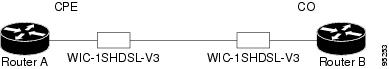
Figure 27 Back-to-Back Setup
SUMMARY STEPS
8.
9.
10.
11.
12.
13.
14.
15.
DETAILED STEPS
Examples
Example of the Configuration Prior to Configuring T1/E1 mode
controller DSL 0/0line-term cpeWhat to Do Next
Configure the router for two-wire T1/E1 mode using the steps shown in the "Configuring Two-Wire CPE T1/E1 Mode" section.
Configuring Two-Wire CPE T1/E1 Mode
Use this section to configure the router for two-wire CPE T1/E1 mode. To configure G.SHDSL service in T1/E1 Framed mode on a Cisco router containing a G.SHDSL WIC, complete the steps in the following sections.
Prerequisites
The following list of prerequisites should be followed for this configuration:
•
•
•
•
Figure 28 Basic Configuration for T1/E1 with a Back-to-Back Setup
Restrictions
The following list of restrictions should be observed for this configuration:
•
–
–
•
–
–
SUMMARY STEPS
Follow this summary of steps to configure Two-Wire CPE T1/E1 Mode.
1.
2.
3.
4.
DETAILED STEPS
Step 1
no mode
Example:Router(config-controller)# no mode
Clears any current logical controller.
Step 2
mode {t1 | e1}
Example:Router(config-controller)# mode e1
Creates a logical T1 or E1 controller.
•
Step 3
controller {t1 | e1} slot/port
Example:Router(config-controller)# controller e1 0/1
Enters controller configuration mode and configures the logical T1/E1 controller created in Step 2.
The keywords and arguments are as follows:
•
•
Step 4
clock source {internal | line}
Example:Router(config-controller)# clock source internal
Configures the clock source on the router:
•
•
Note
Note
What to Do Next
Verify the configuration using the detailed steps in"Verifying Two-Wire CPE T1/E1 Configuration Status" section
Configuring the TDM Clock
Use this section to configure the TDM clock source for voice images on the Cisco 1700 series routers. Configuring TDM clock is a prerequisite for configuring channel-groups in T1/E1 mode, but is an option for configuring ATM mode. The TDM clock configuration is not supported on data-only images.
The tdm clock global configuration command configures the clock source for the G.SHDSL WIC.
For more information about clock configuration for voice on the Cisco 1700 series routers, refer to the "Clock Configuration for Voice Images" in the Clock Configuration for Cisco 1751/1760 Routers document at the following location:
http://www.cisco.com/en/US/docs/routers/access/1700/1751/software/feature/guide/TDMdesc.html
SUMMARY STEPS
1.
or
2.
3.
or
4.
5.
DETAILED STEPS
What to Do Next
Verify the configuration. See the "Verifying Two-Wire CPE T1/E1 Configuration Status" section.
Configuring a Channel Group and a TDM Group
Use this section to configure a channel group and a TDM group. Complete the steps in the following sections.
Prerequisites
The following list of prerequisites should be followed for this configuration:
•
•
•
•
Restrictions
The following list of restrictions should be observed for this configuration:
•
–
–
SUMMARY STEPS
1.
2.
3.
DETAILED STEPS
Configuring a Channel Group
Use this section to configure a channel group. Complete the steps in the following sections.
Prerequisites
The following list of prerequisites should be followed for this configuration:
•
•
•
•
Restrictions
The following list of restrictions should be observed for this configuration:
•
–
–
SUMMARY STEPS
1.
2.
3.
DETAILED STEPS
Example
CPE Configuration
controller DSL 0/0mode e1line-term cpeline-mode 2-wire line-zerodsl-mode shdsl symmetric annex Bignore-error-duration 15snr margin snext -10!!!controller E1 0/0channel-group 0 timeslots 1-31!!!interface Serial0/0:0ip address 10.0.0.2 255.0.0.0!!!CO Configuration
controller DSL 0/1mode e1line-term coline-mode 2-wire line-zerodsl-mode shdsl symmetric annex B!!!controller E1 0/1channel-group 0 timeslots 1-31!!!interface Serial0/1:0ip address 10.0.0.1 255.0.0.0!!!Configuring a TDM Group
Use this section to configure a TDM group. Complete the steps in the following sections.
Prerequisites
The following list of prerequisites should be followed for this configuration:
•
•
•
•
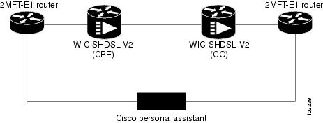
Figure 29 Typical Router Setup
SUMMARY STEPS
1.
2.
DETAILED STEPS
Example
CPE Configuration
controller E1 1/0tdm-group 0 timeslots 1-15!!controller DSL 1/2mode e1line-term cpeline-mode 2-wire line-zerodsl-mode shdsl symmetric annex B!controller E1 1/2tdm-group 0 timeslots 1-15!!!connect hp E1 1/0 0 E1 1/2 0!!CO Configuration
controller E1 1/0tdm-group 0 timeslots 1-15!controller E1 1/1!controller DSL 1/2mode e1line-term coline-mode 2-wire line-zerodsl-mode shdsl symmetric annex B!controller E1 1/2clock source internaltdm-group 0 timeslots 1-15!!!connect hp E1 1/0 0 E1 1/2 0!!!Verifying Two-Wire CPE T1/E1 Configuration Status
Use the following commands to verify your configuration.
SUMMARY STEPS
1.
2.
3.
4.
DETAILED STEPS
Examples
Sample output—The WIC Configured and the Line Up
Router# show controller dsl 0/0DSL 0/0 controller UPSLOT 0:Globespan xDSL controller chipsetDSL mode:SHDSL Annex AFrame mode:UtopiaConfigured Line rate:AutoLine Re-activated 25 times after system bootupLOSW Defect alarm:NoneCRC per second alarm:NoneLine termination:CPECurrent 15 min CRC:0Current 15 min LOSW Defect:0Current 15 min ES:0Current 15 min SES:0Current 15 min UAS:0Previous 15 min CRC:0Previous 15 min LOSW Defect:0Previous 15 min ES:0Previous 15 min SES:0Previous 15 min UAS:0Chipset Version: 1Firmware Version: R1.7Modem Status: Data, Status 1Line rate: 2312 KbpsFramer Sync Status:In SyncRcv Clock Status:In the RangeLoop Attenuation: 0.9880 dBTransmit Power: 7.5 dBReceiver Gain: 21.420 dBSNR Sampling: 39Last Fail Mode: No FailureDying Gasp:PresentSample Output—Show the Software Version
Router# show versionCisco IOS Software, C2600 Software (C2600-IPVOICE-M), Experimental Version 12.3(20040202:201615) [eci 109]Copyright (c) 1986-2004 by Cisco Systems, Inc.Compiled Fri 13-Feb-04 16:48ROM: System Bootstrap, Version 12.2(20011207:134652) [dmize-triple_play_rommon 219], DEVELOPMENT SOFTWARERouter uptime is 1 week, 1 day, 2 hours, 38 minutesSystem returned to ROM by power-onSystem restarted at 14:09:41 UTC Thu Feb 26 2004Running default softwareCisco 2620XM (MPC860P) processor (revision 0x02) with 127627K/3445K bytes of memory.Processor board ID FFFF (1219648036)M860 processor: part number 5, mask 22 DSL controllers1 FastEthernet interface1 ATM interface1 Channelized T1/PRI port32K bytes of NVRAM.49152K bytes of processor board System flash (Read/Write)Configuration register is 0x0This image supports System Controller functionalitySample Output—Building Configuration
Router# show running-configBuilding configuration...Current configuration : 885 bytes!version 12.3service timestamps debug datetime msecservice timestamps log datetime msecno service password-encryption!hostname Router!boot-start-markerboot-end-marker!no logging console!no aaa new-modelprompt router>ip subnet-zero!!!!ip cefno ftp-server write-enable!!!!!!!!!!!!!!controller DSL 1/0mode atmline-term cpeline-rate auto!!controller DSL 1/1mode t1line-term cpe!controller T1 1/1framing sflinecode ami!!!interface ATM1/0ip address 10.0.0.40 255.0.0.0no atm ilmi-keepalivepvc 2/100!!interface FastEthernet1/0ip address 10.0.208.41 255.0.0.0duplex autospeed auto!interface FastEthernet1/1no ip addressshutdownduplex autospeed auto!!!!!!line con 0exec-timeout 0 0privilege level 15line aux 0line vty 0 4exec-timeout 0 0privilege level 15no login!!!endTroubleshooting Tasks
The following commands verify hardware in the router:
•
–
1 DSL controller—If one DSL controller is installed in the router.–
1 ATM network interface(s)—If the DSL controller is configured for mode ATM.–
1 Channelized T1/PRI port(s)—If the DSL controller is configured for mode T1.•
Router# show controllers dsl 0/2DSL 0/2 controller UPSLOT 0: Globespan xDSL controller chipsetDSL mode: SHDSL Annex BFrame mode: UtopiaConfigured Line rate: AutoLine Re-activated 2 times after system bootupLOSW Defect alarm: ACTIVECRC per second alarm: ACTIVELine termination: CPEFPGA Revision: 0xA5Current 15 min CRC: 0Current 15 min LOSW Defect: 0Current 15 min ES: 0Current 15 min SES: 0Current 15 min UAS: 203895Previous 15 min CRC: 0Previous 15 min LOSW Defect: 0Previous 15 min ES: 0Previous 15 min SES: 0Previous 15 min UAS: 0Line-0 statusChipset Version: 1Firmware Version: R2.3.1Modem Status: Data, Status 1Last Fail Mode: No Failure status:0x0Line rate: 2312 KbpsFramer Sync Status: In SyncRcv Clock Status: In the RangeLoop Attenuation: 0.7860 dBTransmit Power: 9.5 dBReceiver Gain: 21.420 dBSNR Sampling: 37Dying Gasp: Present•
Router# show controller t1T1 0/1 is up.Applique type is Channelized T1No alarms detected.alarm-trigger is not setFraming is ESF, Clock Source is Line.Data in current interval (680 seconds elapsed):0 Line Code Violations, 0 Path Code Violations0 Slip Secs, 0 Fr Loss Secs, 0 Line Err Secs, 0 Degraded Mins0 Errored Secs, 0 Bursty Err Secs, 0 Severely Err Secs, 0 Unavail SecsTotal Data (last 24 hours)0 Line Code Violations, 0 Path Code Violations,0 Slip Secs, 0 Fr Loss Secs, 0 Line Err Secs, 0 Degraded Mins,0 Errored Secs, 0 Bursty Err Secs, 0 Severely Err Secs, 0 Unavail Secs•
Router# debug xdsl applicationxDSL application debugging is onRouter#*Mar 12 08:22:59.300: DSL 0/2 xdsl_background_process: XDSL link up boolean event received*Mar 12 08:22:59.300: DSL 0/2 controller Link up! line rate: 2304 Kbps*Mar 12 08:22:59.300: DSL 0/2 xdsl_controller_reset: cdb-state=up*Mar 12 08:22:59.300: %CONTROLLER-5-UPDOWN: Controller DSL 0/2, changed state to up*Mar 12 08:22:59.300: Dslsar data rate 2304*Mar 12 08:22:59.300: DSL 0/2 TipRing 1, Xmit_Power Val 95, xmit_power 9.5*Mar 12 08:22:59.300: DSL 0/2 Mode 2, BW 2304, power_base_value 145, power_backoff 5*Mar 12 08:23:04.956: DSL 0/2 xdsl_background_process: EOC boolean event received*Mar 12 08:23:05.816: DSL 0/2 SNR Sampling: 43 dB*Mar 12 08:23:06.816: DSL 0/2 SNR Sampling: 42 dB*Mar 12 08:23:07.816: DSL 0/2 SNR Sampling: 41 dB*Mar 12 08:23:09.760: DSL 0/2 xdsl_background_process: EOC boolean event received*Mar 12 08:23:09.816: DSL 0/2 SNR Sampling: 40 dB*Mar 12 08:23:10.816: DSL 0/2 SNR Sampling: 40 dB•
Router# debug xdsl driverxDSL driver debugging is on*Mar 12 08:01:04.772: DSL 0/2 dsp interrupt-download next block for line-0*Mar 12 08:01:04.780: DSL 0/2 framer intr_status 0xC0*Mar 12 08:01:05.072: DSL 0/2 dsp interrupt-download next block for line-0*Mar 12 08:01:05.080: DSL 0/2 framer intr_status 0xC0*Mar 12 08:01:06.484: DSL 0/2 dsp interrupt-download next block for line-0*Mar 12 08:01:06.492: DSL 0/2 framer intr_status 0xC0*Mar 12 08:01:08.092: DSL 0/2 dsp interrupt-download next block for line-0*Mar 12 08:01:08.096: DSL 0/2 framer intr_status 0xC0*Mar 12 08:01:19.180: DSL 0/2 dsp interrupt-download next block for line-0*Mar 12 08:01:19.184: DSL 0/2 framer intr_status 0xC0*Mar 12 08:01:19.480: DSL 0/2 dsp interrupt-download next block for line-0*Mar 12 08:01:19.484: DSL 0/2 framer intr_status 0xC0*Mar 12 08:01:19.680: DSL 0/2 dsp interrupt-download next block for line-0*Mar 12 08:01:19.680: DSL 0/2 DSP interrupt disabled*Mar 12 08:01:19.680: DSL 0/2 Download completed for line-0*Mar 12 08:01:19.680: DSL 0/2 Framer interrupt enabled*Mar 12 08:01:19.680: DSL 0/2 framer intr_status 0xC0*Mar 12 08:01:19.680: DSL 0/2 controller Link up! line rate: 2304 Kbps*Mar 12 08:01:19.680: %CONTROLLER-5-UPDOWN: Controller DSL 0/2, changed state to up*Mar 12 08:01:19.680: Dslsar data rate 2304*Mar 12 08:01:22.528: %LINK-3-UPDOWN: Interface ATM0/2, changed state to up*Mar 12 08:01:23.528: %LINEPROTO-5-UPDOWN: Line protocol on Interface ATM0/2, changed state to up*Mar 12 08:01:23.812: DSL 0/2 framer intr_status 0xC4*Mar 12 08:01:23.816: DSL 0/2 framer intr_status 0xC4*Mar 12 08:01:23.904: DSL 0/2 framer intr_status 0xC1*Mar 12 08:01:28.612: DSL 0/2 framer intr_status 0xC4*Mar 12 08:01:28.616: DSL 0/2 framer intr_status 0xC4*Mar 12 08:01:28.708: DSL 0/2 framer intr_status 0xC1*Mar 12 08:01:28.804: DSL 0/2 framer intr_status 0xC1*Mar 12 08:01:33.412: DSL 0/2 framer intr_status 0xC4*Mar 12 08:01:33.420: DSL 0/2 framer intr_status 0xC4*Mar 12 08:01:33.508: DSL 0/2 framer intr_status 0xC1*Mar 12 08:01:33.604: DSL 0/2 framer intr_status 0xC1*Mar 12 08:01:33.700: DSL 0/2 framer intr_status 0xC1*Mar 12 08:01:38.212: DSL 0/2 framer intr_status 0xC4*Mar 12 08:01:38.220: DSL 0/2 framer intr_status 0xC4*Mar 12 08:01:38.308: DSL 0/2 framer intr_status 0xC1•
Router# debug xdsl eocxDSL EOC debugging is onRouter#*Mar 12 08:19:08.564: DSL 0/2 controller Link up! line rate: 2304 Kbps*Mar 12 08:19:08.564: %CONTROLLER-5-UPDOWN: Controller DSL 0/2, changed state to up*Mar 12 08:19:08.564: Dslsar data rate 2304*Mar 12 08:19:12.528: %LINK-3-UPDOWN: Interface ATM0/2, changed state to up*Mar 12 08:19:13.528: %LINEPROTO-5-UPDOWN: Line protocol on Interface ATM0/2, changed state to up*Mar 12 08:19:14.500: DSL 0/2: line 0 EOC Rcv Intr :: 0xC4*Mar 12 08:19:14.500: DSL 0/2:Current length 40 GTI_OK*Mar 12 08:19:14.500: DSL 0/2: GT_FAIL*Mar 12 08:19:14.500: Rx EOC remove transparency:: 12 1 0 39 EF*Mar 12 08:19:14.500: data_transparency_remove: Done, eoc packet size = 5*Mar 12 08:19:14.500: Good eoc packet received*Mar 12 08:19:14.500: incoming request eocmsgid: 1*Mar 12 08:19:14.500: Tx Converted EOC message:: 21 81 1 43 43 49 53 43 4F 0 0 0 2 1 0 E9 61*Mar 12 08:19:14.500: data_transparency_add: eoc packet size - before 17, after 17*Mar 12 08:19:14.504: DSL 0/2: line 0 EOC Rcv Intr :: 0xC4*Mar 12 08:19:14.504: DSL 0/2: Current length 40 GTI_EOM*Mar 12 08:19:14.504: DSL 0/2: GT_FAIL*Mar 12 08:19:14.600: DSL 0/2: line 0 EOC TX Complete Intr :: 0xC1*Mar 12 08:19:19.300: DSL 0/2: line 0 EOC Rcv Intr :: 0xC4*Mar 12 08:19:19.300: DSL 0/2:Current length 40 GTI_OK*Mar 12 08:19:19.300: DSL 0/2: GT_FAIL*Mar 12 08:19:19.300: Rx EOC remove transparency:: 12 2 74 8A*Mar 12 08:19:19.300: data_transparency_remove: Done, eoc packet size = 4*Mar 12 08:19:19.300: Good eoc packet received*Mar 12 08:19:19.300: incoming request eocmsgid: 2*Mar 12 08:19:19.300: Tx Converted EOC message:: 21 82 1 0 0 0 0 0 52 32 2E 33 2E 31 43 4E 53 38 44 44 30 41 41 41 43 43 49 53 43 4F 0 0 0 43 53 43 4F 2D 31 53 48 44 53 4C 0 46 48 48 30 37 31 39 30 31 4C 51 0 31 32 2E 33 28 32 30 30 33 30 36 0 A8 F3*Mar 12 08:19:19.300: data_transparency_add: eoc packet size - before 71, after 71*Mar 12 08:19:19.308: DSL 0/2: line 0 EOC Rcv Intr :: 0xC4*Mar 12 08:19:19.308: DSL 0/2: Current length 40 GTI_EOM*Mar 12 08:19:19.308: DSL 0/2: GT_FAIL*Mar 12 08:19:19.400: DSL 0/2: line 0 EOC TX Complete Intr :: 0xC1*Mar 12 08:19:19.496: DSL 0/2: line 0 EOC TX Complete Intr :: 0xC1*Mar 12 08:19:24.100: DSL 0/2: line 0 EOC Rcv Intr :: 0xC4*Mar 12 08:19:24.100: DSL 0/2:Current length 40 GTI_OK*Mar 12 08:19:24.100: DSL 0/2: GT_FAIL*Mar 12 08:19:24.100: Rx EOC remove transparency:: 12 B B5 17*Mar 12 08:19:24.100: data_transparency_remove: Done, eoc packet size = 4*Mar 12 08:19:24.100: Good eoc packet received*Mar 12 08:19:24.100: incoming request eocmsgid: 11*Mar 12 08:19:24.100: Tx Converted EOC message:: 21 8B 10 0 1 C5 DD*Mar 12 08:19:24.100: data_transparency_add: eoc packet size - before 7, after 7*Mar 12 08:19:24.104: Tx Converted EOC message:: 21 8C 0 10 0 0 0 0 0 0 C 85 1 B0 4A*Mar 12 08:19:24.104: data_transparency_add: eoc packet size - before 15, after 15*Mar 12 08:19:24.104: size of eoc status response :: 13*Mar 12 08:19:24.104: Tx Converted EOC message:: 21 89 5 52 93*Mar 12 08:19:24.104: data_transparency_add: eoc packet size - before 5, after 5*Mar 12 08:19:24.104: size of eoc status response :: 3GSI Tx buffer yet to transmit*Mar 12 08:19:24.108: DSL 0/2: line 0 EOC Rcv Intr :: 0xC4*Mar 12 08:19:24.108: DSL 0/2: Current length 40 GTI_EOM*Mar 12 08:19:24.108: DSL 0/2: GT_FAIL*Mar 12 08:19:24.204: DSL 0/2: line 0 EOC TX Complete Intr :: 0xC1*Mar 12 08:19:24.300: DSL 0/2: line 0 EOC TX Complete Intr :: 0xC1*Mar 12 08:19:24.396: DSL 0/2: line 0 EOC TX Complete Intr :: 0xC1*Mar 12 08:19:28.904: DSL 0/2: line 0 EOC Rcv Intr :: 0xC4*Mar 12 08:19:28.904: DSL 0/2:Current length 40 GTI_OK*Mar 12 08:19:28.904: DSL 0/2: GT_FAIL*Mar 12 08:19:28.904: Rx EOC remove transparency:: 12 11 6E A8*Mar 12 08:19:28.904: data_transparency_remove: Done, eoc packet size = 4*Mar 12 08:19:28.904: Good eoc packet received*Mar 12 08:19:28.904: incoming request eocmsgid: 17*Mar 12 08:19:28.904: Tx Converted EOC message:: 21 91 0 0 0 D6 56*Mar 12 08:19:28.904: data_transparency_add: eoc packet size - before 7, after 7*Mar 12 08:19:28.904: size of eoc status response :: 5*Mar 12 08:19:28.908: DSL 0/2: line 0 EOC Rcv Intr :: 0xC4*Mar 12 08:19:28.908: DSL 0/2: Current length 40 GTI_EOM*Mar 12 08:19:28.908: DSL 0/2: GT_FAIL*Mar 12 08:19:29.004: DSL 0/2: line 0 EOC TX Complete Intr :: 0xC1*Mar 12 08:19:33.704: DSL 0/2: line 0 EOC Rcv Intr :: 0xC4*Mar 12 08:19:33.704: DSL 0/2:Current length 40 GTI_OK*Mar 12 08:19:33.704: DSL 0/2: GT_FAIL*Mar 12 08:19:33.704: Rx EOC remove transparency:: 12 B B5 17*Mar 12 08:19:33.704: data_transparency_remove: Done, eoc packet size = 4*Mar 12 08:19:33.704: Good eoc packet received*Mar 12 08:19:33.704: incoming request eocmsgid: 11*Mar 12 08:19:33.704: Tx Converted EOC message:: 21 8B E 0 1 4B 48*Mar 12 08:19:33.704: data_transparency_add: eoc packet size - before 7, after 7*Mar 12 08:19:33.704: Tx Converted EOC message:: 21 8C 0 E 0 0 0 0 0 0 9 5 1 68 AC*Mar 12 08:19:33.704: data_transparency_add: eoc packet size - before 15, after 15The following example displays a sample output using the undebug form of this command to turn off the monitoring:
Router# undebug xdsl eocxDSL EOC debugging is off•
Router# debug xdsl errorxDSL error debugging is onRouter#Configuration Examples for T1/E1 Mode for SHDSL
The following are configuration examples for the T1/E1 Mode for SHDSL feature:
•
•
•
•
•
Router A: CPE Configuration Example
controller E1 1/0tdm-group 0 timeslots 1-15!!controller DSL 1/2mode e1line-term cpeline-mode 2-wire line-zerodsl-mode shdsl symmetric annex B!controller E1 1/2tdm-group 0 timeslots 1-15!!!connect hp E1 1/0 0 E1 1/2 0!!Router B: CO Configuration Example
controller E1 1/0tdm-group 0 timeslots 1-15!controller E1 1/1!controller DSL 1/2mode e1line-term coline-mode 2-wire line-zerodsl-mode shdsl symmetric annex B!controller E1 1/2clock source internaltdm-group 0 timeslots 1-15!!!connect hp E1 1/0 0 E1 1/2 0!!!PBX Voice TDM Traffic over SHDSL Example
Figure 30 Typical PBX Voice TDM Traffic Setup
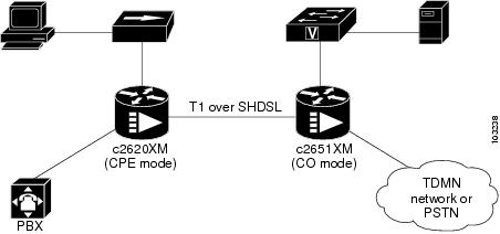
In this example, a WIC-1SHDSL-V2 is used on both sides to link the Cisco 2620XM and the Cisco 2651XM by using one pair of copper wire, as shown in Figure 30. The two WICs are configured into T1 mode.
Under newly created logical T1 controller at the Cisco 2620XM router, ten TDM groups are allocated to deliver TDM voice traffic from the PBX. The TDM voice traffic from the PBX passes first into the VWIC-2MFT-T1 at the Cisco 2620 router, where the voice traffic is switched onto the WIC-1SHDSL-V2 and in turn is delivered over SHDSL to the CO side, the Cisco 2651XM. At the Cisco 2651XM, the TDM voice traffic is switched and passed onto the TDM or PSTN network, which can be done through another VWIC-2MFT-T1 at the CO side.
In the same T1 logical Controllers on both CPE and CO sides, the left time slots are allocated to channel-groups. The created channel-groups are used to make serial interfaces at both CPE and CO sides. The logical serial interfaces can be used to deliver any IP traffic; for example, the PC can communicate to file server on the remote CO side.
The following sample configurations are given for reference.
CPE Sample Configuration
Current configuration : 1081 bytes!version 12.3service configservice timestamps debug datetime msecservice timestamps log datetime msecno service password-encryption!hostname 2651XM-CPE!boot-start-markerboot-end-marker!!no aaa new-modelip subnet-zero!!!!ip host dirt 192.168.254.254no ftp-server write-enable!!!controller DSL 1/0mode t1line-term cpe!controller T1 1/0framing esfcrc-threshold 0linecode b8zschannel-group 1 timeslots 11-24tdm-group 0 timeslots 1-10 type e&m!controller T1 1/1framing esfcrc-threshold 320linecode b8zstdm-group 0 timeslots 1-10 type e&m!controller T1 1/2framing sfcrc-threshold 320linecode ami!!interface FastEthernet0/0ip address dhcpduplex autospeed auto!interface FastEthernet0/1no ip addressshutdownduplex autospeed auto!interface Serial1/0:1ip address 10.0.0.2 255.0.0.0!ip classlessip http server!!connect PBX_TDMDSL T1 1/0 0 T1 1/1 0!!!control-plane!!line con 0exec-timeout 0 0privilege level 15line aux 0line vty 0 4exec-timeout 0 0privilege level 15no login!!!endCO Sample Configuration
version 12.3service timestamps debug datetime msecservice timestamps log datetime msecno service password-encryption!hostname 2620XM-CO!boot-start-markerboot-end-marker!!no aaa new-modelip subnet-zero!!!!ip host dirt 192.168.254.254no ftp-server write-enable!!!!controller DSL 1/0mode t1line-term co!controller T1 1/0framing esfcrc-threshold 0clock source internallinecode b8zschannel-group 1 timeslots 11-24tdm-group 0 timeslots 1-10 type e&m!controller T1 1/1framing esfcrc-threshold 320linecode b8zstdm-group 0 timeslots 1-10 type e&m!controller T1 1/2framing sfcrc-threshold 320linecode ami!!interface FastEthernet0/0ip address dhcpduplex autospeed auto!interface Serial1/0:1ip address 10.0.0.1 255.0.0.0!ip classlessip http server!!connect PBX_TDMDSL T1 1/0 0 T1 1/1 0!!!!control-plane!!line con 0exec-timeout 0 0privilege level 15line aux 0line vty 0 4exec-timeout 0 0privilege level 15no login!!!endConfiguration Examples for the Cisco 1760 Router in E1 Mode with Voice
This section contains output examples for configuring the Cisco 1760 CO and the Cisco 1760 CPE in E1 mode with voice.
Configuration Example for a Cisco 1760 CO in E1 Mode
Router#p 12.0.0.2Type escape sequence to abort.Sending 5, 100-byte ICMP Echos to 12.0.0.2, timeout is 2 seconds:!!!!!Success rate is 100 percent (5/5), round-trip min/avg/max = 4/4/8 msRouter#p 20.0.0.2Type escape sequence to abort.Sending 5, 100-byte ICMP Echos to 20.0.0.2, timeout is 2 seconds:!!!!!Success rate is 100 percent (5/5), round-trip min/avg/max = 4/6/8 msRouter#show runBuilding configuration...Current configuration : 913 bytes!version 12.3service timestamps debug datetime msecservice timestamps log datetime msecno service password-encryption!hostname Router!boot-start-markerboot-end-marker!!tdm multichannel E1 1/0 timeslots 24-31tdm clock E1 1/0 data import onboard internalmmi polling-interval 60no mmi auto-configureno mmi pvcmmi snmp-timeout 180no aaa new-modelip subnet-zeroip cef!!!!no ftp-server write-enable!!!!!controller DSL 1/0mode e1line-term coline-mode 2-wire!controller E1 1/0channel-group 0 timeslots 1-12channel-group 1 timeslots 24-31 speed 56!!!interface FastEthernet0/0no ip addressshutdownspeed auto!interface Serial1/0:0ip address 12.0.0.1 255.0.0.0!interface Serial1/0:1ip address 20.0.0.1 255.0.0.0!ip classlessno ip http server!!!control-plane!!!!line con 0line aux 0line vty 0 4!no scheduler allocateendRouter#Router#show controller e1 1/0E1 1/0 is up.Applique type is Channelized E1 - balancedReceiver has remote alarm.alarm-trigger is not setFraming is CRC4, Clock Source is Internal.Data in current interval (201 seconds elapsed):0 Line Code Violations, 0 Path Code Violations0 Slip Secs, 0 Fr Loss Secs, 0 Line Err Secs, 0 Degraded Mins0 Errored Secs, 0 Bursty Err Secs, 0 Severely Err Secs, 0 Unavail SecsRouter#show controller dsl 1/0DSL 1/0 controller UPGlobespan xDSL controller chipsetDSL mode: SHDSL Annex AFrame mode: E1 SlottedLine Re-activated 0 times after system bootupLOSW Defect alarm: ACTIVECRC per second alarm: ACTIVELine termination: COFPGA Revision: 0xA9Current 15 min CRC: 0Current 15 min LOSW Defect: 0Current 15 min ES: 0Current 15 min SES: 0Current 15 min UAS: 0Previous 15 min CRC: 0Previous 15 min LOSW Defect: 0Previous 15 min ES: 0Previous 15 min SES: 0Previous 15 min UAS: 0Line-0 statusChipset Version: 1Firmware Version: A29733Modem Status: Data, Status 1Last Fail Mode: No Failure status:0x0Line rate: 2056 KbpsFramer Sync Status: In SyncRcv Clock Status: Out of RangeLoop Attenuation: 0.9890 dBTransmit Power: 7.5 dBReceiver Gain: 19.5420 dBSNR Sampling: 39.1570 dBDying Gasp: PresentRouter#Router#show versionCisco IOS Software, C1700 Software (C1700-IPVOICE-M), Experimental Version 12.3(20040114:170452) [gvsriks-crusher_pi5 101]Copyright (c) 1986-2004 by Cisco Systems, Inc.Compiled Thu 15-Jan-04 22:18 by gvsriksROM: System Bootstrap, Version 12.2(4r)XL, RELEASE SOFTWARE (fc1)Router uptime is 34 minutesSystem returned to ROM by power-onRunning default softwareCisco 1760 (MPC860P) processor (revision 0x200) with 61584K/3952K bytes of memory.Processor board ID VEN05300043 (2247167129), with hardware revision 0000MPC860P processor: part number 5, mask 21 DSL controller1 FastEthernet interface2 Serial interfaces1 Channelized E1/PRI port32K bytes of NVRAM.16384K bytes of processor board System flash (Read/Write)Configuration register is 0x40Router#--------------------------------------------------------------------------------Router#sh int se 1/0:0Serial1/0:0 is up, line protocol is upHardware is DSX1Internet address is 12.0.0.1/8MTU 1500 bytes, BW 768 Kbit, DLY 20000 usec,reliability 255/255, txload 1/255, rxload 1/255Encapsulation HDLC, loopback not setKeepalive set (10 sec)Last input 00:00:01, output 00:00:00, output hang neverLast clearing of "show interface" counters 00:08:29Input queue: 0/75/0/0 (size/max/drops/flushes); Total output drops: 0Queueing strategy: weighted fairOutput queue: 0/1000/64/0 (size/max total/threshold/drops)Conversations 0/1/256 (active/max active/max total)Reserved Conversations 0/0 (allocated/max allocated)Available Bandwidth 576 kilobits/sec5 minute input rate 0 bits/sec, 0 packets/sec5 minute output rate 0 bits/sec, 0 packets/sec1064 packets input, 264136 bytes, 0 no bufferReceived 59 broadcasts, 0 runts, 0 giants, 0 throttles0 input errors, 0 CRC, 0 frame, 0 overrun, 0 ignored, 0 abort1065 packets output, 264435 bytes, 0 underruns0 output errors, 0 collisions, 0 interface resets0 output buffer failures, 0 output buffers swapped out0 carrier transitionsTimeslot(s) Used:1-12, SCC: 0, Transmitter delay is 0 flagsRouter#Router#show int se 1/0:1Serial1/0:1 is up, line protocol is upHardware is DSX1Internet address is 20.0.0.1/8MTU 1500 bytes, BW 448 Kbit, DLY 20000 usec,reliability 255/255, txload 1/255, rxload 1/255Encapsulation HDLC, loopback not setKeepalive set (10 sec)Last input 00:00:08, output 00:00:05, output hang neverLast clearing of "show interface" counters 00:08:53Input queue: 0/75/0/0 (size/max/drops/flushes); Total output drops: 0Queueing strategy: weighted fairOutput queue: 0/1000/64/0 (size/max total/threshold/drops)Conversations 0/1/256 (active/max active/max total)Reserved Conversations 0/0 (allocated/max allocated)Available Bandwidth 336 kilobits/sec5 minute input rate 0 bits/sec, 0 packets/sec5 minute output rate 0 bits/sec, 0 packets/sec2648 packets input, 1485798 bytes, 0 no bufferReceived 62 broadcasts, 0 runts, 0 giants, 0 throttles0 input errors, 0 CRC, 0 frame, 0 overrun, 0 ignored, 0 abort2648 packets output, 1485798 bytes, 0 underruns0 output errors, 0 collisions, 0 interface resets0 output buffer failures, 0 output buffers swapped out0 carrier transitionsRouter#Configuration Example for a Cisco 1760 CPE in E1 Mode
Router#p 12.0.0.1Type escape sequence to abort.Sending 5, 100-byte ICMP Echos to 12.0.0.1, timeout is 2 seconds:!!!!!Success rate is 100 percent (5/5), round-trip min/avg/max = 4/5/8 msRouter#p 20.0.0.1Type escape sequence to abort.Sending 5, 100-byte ICMP Echos to 20.0.0.1, timeout is 2 seconds:!!!!!Success rate is 100 percent (5/5), round-trip min/avg/max = 8/8/8 msRouter#show runBuilding configuration...Current configuration : 902 bytes!version 12.3service timestamps debug datetime msecservice timestamps log datetime msecno service password-encryption!hostname Router!boot-start-markerboot-end-marker!!tdm multichannel E1 1/0 timeslots 24-31tdm clock E1 1/0 data export linemmi polling-interval 60no mmi auto-configureno mmi pvcmmi snmp-timeout 180no aaa new-modelip subnet-zeroip cef!!!!no ftp-server write-enable!!!!!controller DSL 1/0mode e1line-term cpeline-mode 2-wire!controller E1 1/0channel-group 0 timeslots 1-12channel-group 1 timeslots 24-31 speed 56!!!interface FastEthernet0/0no ip addressshutdownspeed auto!interface Serial1/0:0ip address 12.0.0.2 255.0.0.0!interface Serial1/0:1ip address 20.0.0.2 255.0.0.0!ip classlessno ip http server!!!control-plane!!!!line con 0line aux 0line vty 0 4!no scheduler allocateendRouter#Router#show controller e1 1/0E1 1/0 is up.Applique type is Channelized E1 - balancedNo alarms detected.alarm-trigger is not setFraming is CRC4, Clock Source is Line.Data in current interval (345 seconds elapsed):0 Line Code Violations, 0 Path Code Violations0 Slip Secs, 0 Fr Loss Secs, 0 Line Err Secs, 0 Degraded Mins0 Errored Secs, 0 Bursty Err Secs, 0 Severely Err Secs, 0 Unavail SecsRouter#Router#show controller dsl 1/0DSL 1/0 controller UPGlobespan xDSL controller chipsetDSL mode: SHDSL Annex AFrame mode: E1 SlottedLine Re-activated 0 times after system bootupLOSW Defect alarm: ACTIVECRC per second alarm: ACTIVELine termination: CPEFPGA Revision: 0xA9Current 15 min CRC: 0Current 15 min LOSW Defect: 0Current 15 min ES: 0Current 15 min SES: 0Current 15 min UAS: 0Previous 15 min CRC: 0Previous 15 min LOSW Defect: 0Previous 15 min ES: 0Previous 15 min SES: 0Previous 15 min UAS: 0Line-0 statusChipset Version: 1Firmware Version: A29733Modem Status: Data, Status 1Last Fail Mode: No Failure status:0x0Line rate: 2056 KbpsFramer Sync Status: In SyncRcv Clock Status: In the RangeLoop Attenuation: 1.4160 dBTransmit Power: 7.5 dBReceiver Gain: 19.5420 dBSNR Sampling: 38.4000 dBDying Gasp: PresentRouter#Router#Router#Router#show versionCisco IOS Software, C1700 Software (C1700-IPVOICE-M), Experimental Version 12.3(20040114:170452) [gvsriks-crusher_pi5 101]Copyright (c) 1986-2004 by Cisco Systems, Inc.Compiled Thu 15-Jan-04 22:18 by gvsriksROM: System Bootstrap, Version 12.2(7r)XM2, RELEASE SOFTWARE (fc1)Router uptime is 37 minutesSystem returned to ROM by power-onRunning default softwareCisco 1760 (MPC860P) processor (revision 0x500) with 87799K/10505K bytes of memory.Processor board ID FOC073817AG (2398817686), with hardware revision 0000MPC860P processor: part number 5, mask 21 DSL controller1 FastEthernet interface2 Serial interfaces1 Channelized E1/PRI port32K bytes of NVRAM.32768K bytes of processor board System flash (Read/Write)Configuration register is 0x0Router#Router#sh int se 1/0:0Serial1/0:0 is up, line protocol is upHardware is DSX1Internet address is 12.0.0.2/8MTU 1500 bytes, BW 768 Kbit, DLY 20000 usec,reliability 255/255, txload 1/255, rxload 1/255Encapsulation HDLC, loopback not setKeepalive set (10 sec)Last input 00:00:08, output 00:00:09, output hang neverLast clearing of "show interface" counters 00:11:42Input queue: 0/75/0/0 (size/max/drops/flushes); Total output drops: 0Queueing strategy: weighted fairOutput queue: 0/1000/64/0 (size/max total/threshold/drops)Conversations 0/1/256 (active/max active/max total)Reserved Conversations 0/0 (allocated/max allocated)Available Bandwidth 576 kilobits/sec5 minute input rate 0 bits/sec, 0 packets/sec5 minute output rate 0 bits/sec, 0 packets/sec1087 packets input, 265788 bytes, 0 no bufferReceived 82 broadcasts, 0 runts, 0 giants, 0 throttles0 input errors, 0 CRC, 0 frame, 0 overrun, 0 ignored, 0 abort1086 packets output, 265489 bytes, 0 underruns0 output errors, 0 collisions, 0 interface resets0 output buffer failures, 0 output buffers swapped out0 carrier transitionsTimeslot(s) Used:1-12, SCC: 0, Transmitter delay is 0 flagsRouter#Router#show int se 1/0:1Serial1/0:1 is up, line protocol is upHardware is DSX1Internet address is 20.0.0.2/8MTU 1500 bytes, BW 448 Kbit, DLY 20000 usec,reliability 255/255, txload 1/255, rxload 1/255Encapsulation HDLC, loopback not setKeepalive set (10 sec)Last input 00:00:05, output 00:00:08, output hang neverLast clearing of "show interface" counters 00:11:58Input queue: 0/75/0/0 (size/max/drops/flushes); Total output drops: 0Queueing strategy: weighted fairOutput queue: 0/1000/64/0 (size/max total/threshold/drops)Conversations 0/1/256 (active/max active/max total)Reserved Conversations 0/0 (allocated/max allocated)Available Bandwidth 336 kilobits/sec5 minute input rate 0 bits/sec, 0 packets/sec5 minute output rate 0 bits/sec, 0 packets/sec2670 packets input, 1487151 bytes, 0 no bufferReceived 84 broadcasts, 0 runts, 0 giants, 0 throttles0 input errors, 0 CRC, 0 frame, 0 overrun, 0 ignored, 0 abort2669 packets output, 1487127 bytes, 0 underruns0 output errors, 0 collisions, 0 interface resets0 output buffer failures, 0 output buffers swapped out0 carrier transitionsRouter#Configuration Examples for the Cisco 1760 Router in T1 Mode with Voice
This section contains output examples for configuring the Cisco 1760 CO and the Cisco 1760 CPE in T1 mode using a voice image.
Configuration Example for a Cisco 1760 CO in T1 Mode
Router#show runBuilding configuration...Current configuration :906 bytes!version 12.3service timestamps debug datetime msecservice timestamps log datetime msecno service password-encryption!hostname Router!boot-start-markerboot-end-marker!!tdm multichannel T1 1/0 timeslots 16-24tdm clock T1 1/0 data import onboard internalmmi polling-interval 60no mmi auto-configureno mmi pvcmmi snmp-timeout 180no aaa new-modelip subnet-zeroip cef!!!!no ftp-server write-enable!!!!!controller DSL 1/0mode t1line-term co!controller T1 1/0framing sfchannel-group 0 timeslots 1-12channel-group 1 timeslots 16-24 speed 56!!!interface FastEthernet0/0no ip addressshutdownspeed auto!interface Serial1/0:0ip address 12.0.0.1 255.0.0.0!interface Serial1/0:1ip address 20.0.0.1 255.0.0.0!ip classlessno ip http server!!!control-plane!!!!line con 0line aux 0line vty 0 4!no scheduler allocateendRouter#Router#show versionCisco IOS Software, C1700 Software (C1700-IPVOICE-M), Experimental Version 12.3(20040114:170452) [gvsriks-crusher_pi5 101]Copyright (c) 1986-2004 by Cisco Systems, Inc.Compiled Thu 15-Jan-04 22:18 by gvsriksROM:System Bootstrap, Version 12.2(4r)XL, RELEASE SOFTWARE (fc1)Router uptime is 2 hours, 7 minutesSystem returned to ROM by power-onRunning default softwareCisco 1760 (MPC860P) processor (revision 0x200) with 61584K/3952K bytes of memory.Processor board ID VEN05300043 (2247167129), with hardware revision 0000MPC860P processor:part number 5, mask 21 DSL controller1 FastEthernet interface2 Serial interfaces1 Channelized T1/PRI port32K bytes of NVRAM.16384K bytes of processor board System flash (Read/Write)Configuration register is 0x40Router#---------------------------------------------------------------------------------------Router#ping 12.0.0.2 da dd repeat 1000 si 256Type escape sequence to abort.Sending 1000, 256-byte ICMP Echos to 12.0.0.2, timeout is 2 seconds:Packet has data pattern 0x00DD!!!!!!!!!!!!!!!!!!!!!!!!!!!!!!!!!!!!!!!!!!!!!!!!!!!!!!!!!!!!!!!!!!!!!!!!!!!!!!!!!!!!!!!!!!!!!!!!!!!!!!!!!!!!!!!!!!!!!!!!!!!!!!!!!!!!!!!!!!!!!!!!!!!!!!!!!!!!!!!!!!!!!!!!!!!!!!!!!!!!!!!!!!!!!!!!!!!!!!!!!!!!!!!!!!!!!!!!!!!!!!!!!!!!!!!!!!!!!!!!!!!!!!!!!!!!!!!!!!!!!!!!!!!!!!!!!!!!!!!!!!!!!!!!!!!!!!!!!!!!!!!!!!!!!!!!!!!!!!!!!!!!!!!!!!!!!!!!!!!!!!!!!!!!!!!!!!!!!!!!!!!!!!!!!!!!!!!!!!!!!!!!!!!!!!!!!!!!!!!!!!!!!!!!!!!!!!!!!!!!!!!!!!!!!!!!!!!!!!!!Success rate is 100 percent (1000/1000), round-trip min/avg/max = 8/8/32 msRouter#Router#Router#show controller t1 1/0T1 1/0 is up.Applique type is Channelized T1No alarms detected.alarm-trigger is not setFraming is SF, Clock Source is Internal.Data in current interval (37 seconds elapsed):0 Line Code Violations, 0 Path Code Violations0 Slip Secs, 0 Fr Loss Secs, 0 Line Err Secs, 0 Degraded Mins0 Errored Secs, 0 Bursty Err Secs, 0 Severely Err Secs, 0 Unavail SecsRouter#show controller dsl 1/0DSL 1/0 controller UPGlobespan xDSL controller chipsetDSL mode:SHDSL Annex AFrame mode:T1Line Re-activated 0 times after system bootupLOSW Defect alarm:ACTIVECRC per second alarm:ACTIVELine termination:COFPGA Revision:0xA9Current 15 min CRC:0Current 15 min LOSW Defect:0Current 15 min ES:0Current 15 min SES:0Current 15 min UAS:0Previous 15 min CRC:0Previous 15 min LOSW Defect:0Previous 15 min ES:0Previous 15 min SES:0Previous 15 min UAS:0Line-0 statusChipset Version: 1Firmware Version: A29733Modem Status: Data, Status 1Last Fail Mode: No Failure status:0x0Line rate: 1552 KbpsFramer Sync Status:In SyncRcv Clock Status:Out of RangeLoop Attenuation: 0.4580 dBTransmit Power: 7.5 dBReceiver Gain: 22.5420 dBSNR Sampling: 36.6390 dBDying Gasp:PresentRouter#Router#show int se 1/0:0Serial1/0:0 is up, line protocol is upHardware is DSX1Internet address is 12.0.0.1/8MTU 1500 bytes, BW 768 Kbit, DLY 20000 usec,reliability 255/255, txload 1/255, rxload 1/255Encapsulation HDLC, loopback not setKeepalive set (10 sec)Last input 00:00:09, output 00:00:06, output hang neverLast clearing of "show interface" counters 00:06:40Input queue:0/75/0/0 (size/max/drops/flushes); Total output drops:0Queueing strategy:weighted fairOutput queue:0/1000/64/0 (size/max total/threshold/drops)Conversations 0/1/256 (active/max active/max total)Reserved Conversations 0/0 (allocated/max allocated)Available Bandwidth 576 kilobits/sec5 minute input rate 0 bits/sec, 0 packets/sec5 minute output rate 0 bits/sec, 0 packets/sec1047 packets input, 263053 bytes, 0 no bufferReceived 47 broadcasts, 0 runts, 0 giants, 0 throttles0 input errors, 0 CRC, 0 frame, 0 overrun, 0 ignored, 0 abort1047 packets output, 263053 bytes, 0 underruns0 output errors, 0 collisions, 0 interface resets0 output buffer failures, 0 output buffers swapped out0 carrier transitionsTimeslot(s) Used:1-12, SCC:0, Transmitter delay is 0 flagsRouter#Router#show int se 1/0:1Serial1/0:1 is up, line protocol is upHardware is DSX1Internet address is 20.0.0.1/8MTU 1500 bytes, BW 504 Kbit, DLY 20000 usec,reliability 255/255, txload 1/255, rxload 1/255Encapsulation HDLC, loopback not setKeepalive set (10 sec)Last input 00:00:03, output 00:00:09, output hang neverLast clearing of "show interface" counters 00:06:54Input queue:0/75/0/0 (size/max/drops/flushes); Total output drops:0Queueing strategy:weighted fairOutput queue:0/1000/64/0 (size/max total/threshold/drops)Conversations 0/1/256 (active/max active/max total)Reserved Conversations 0/0 (allocated/max allocated)Available Bandwidth 378 kilobits/sec5 minute input rate 0 bits/sec, 0 packets/sec5 minute output rate 0 bits/sec, 0 packets/sec1049 packets input, 263101 bytes, 0 no bufferReceived 49 broadcasts, 0 runts, 0 giants, 0 throttles0 input errors, 0 CRC, 0 frame, 0 overrun, 0 ignored, 0 abort1048 packets output, 263077 bytes, 0 underruns0 output errors, 0 collisions, 0 interface resets0 output buffer failures, 0 output buffers swapped out0 carrier transitionsRouter#Configuration Example for a Cisco 1760 CPE in T1 Mode
Router#show runBuilding configuration...Current configuration :895 bytes!version 12.3service timestamps debug datetime msecservice timestamps log datetime msecno service password-encryption!hostname Router!boot-start-markerboot-end-marker!!tdm multichannel T1 1/0 timeslots 16-24tdm clock T1 1/0 data export linemmi polling-interval 60no mmi auto-configureno mmi pvcmmi snmp-timeout 180no aaa new-modelip subnet-zeroip cef!!!!no ftp-server write-enable!!!!!!controller DSL 1/0mode t1line-term cpe!controller T1 1/0framing sfchannel-group 0 timeslots 1-12channel-group 1 timeslots 16-24 speed 56!!!interface FastEthernet0/0no ip addressshutdownspeed auto!interface Serial1/0:0ip address 12.0.0.2 255.0.0.0!interface Serial1/0:1ip address 20.0.0.2 255.0.0.0!ip classlessno ip http server!!!control-plane!!!!!line con 0line aux 0line vty 0 4!no scheduler allocateendRouter#Router#show versionCisco IOS Software, C1700 Software (C1700-IPVOICE-M), Experimental Version 12.3(20040114:170452) [gvsriks-crusher_pi5 101]Copyright (c) 1986-2004 by Cisco Systems, Inc.Compiled Thu 15-Jan-04 22:18 by gvsriksROM:System Bootstrap, Version 12.2(7r)XM2, RELEASE SOFTWARE (fc1)Router uptime is 2 hours, 5 minutesSystem returned to ROM by power-onRunning default softwareCisco 1760 (MPC860P) processor (revision 0x500) with 87799K/10505K bytes of memory.Processor board ID FOC073817AG (2398817686), with hardware revision 0000MPC860P processor:part number 5, mask 21 DSL controller1 FastEthernet interface2 Serial interfaces1 Channelized T1/PRI port32K bytes of NVRAM.32768K bytes of processor board System flash (Read/Write)Configuration register is 0x0Router#ping 20.0.0.1 da cc repeat 1000 size 256Type escape sequence to abort.Sending 1000, 256-byte ICMP Echos to 20.0.0.1, timeout is 2 seconds:Packet has data pattern 0x00CC!!!!!!!!!!!!!!!!!!!!!!!!!!!!!!!!!!!!!!!!!!!!!!!!!!!!!!!!!!!!!!!!!!!!!!!!!!!!!!!!!!!!!!!!!!!!!!!!!!!!!!!!!!!!!!!!!!!!!!!!!!!!!!!!!!!!!!!!!!!!!!!!!!!!!!!!!!!!!!!!!!!!!!!!!!!!!!!!!!!!!!!!!!!!!!!!!!!!!!!!!!!!!!!!!!!!!!!!!!!!!!!!!!!!!!!!!!!!!!!!!!!!!!!!!!!!!!!!!!!!!!!!!!!!!!!!!!!!!!!!!!!!!!!!!!!!!!!!!!!!!!!!!!!!!!!!!!!!!!!!!!!!!!!!!!!!!!!!!!!!!!!!!!!!!!!!!!!!!!!!!!!!!!!!!!!!!!!!!!!!!!!!!!!!!!!!!!!!!!!!!!!!!!!!!!!!!!!!!!!!!!!!!!!!!!!!!!!!!!!!!!!!!!!!!!!!!!!!!!!!!!!!!!!!!!!!!!!!!!!!!!!!!!!!!!!!!!!!!!!!!!!!!!!!!!!!!!!!!!!!!!!!!!!!!!!!!!!!!!!!!!!!!!!!!!!!!!!!!!!!!!!!!!!!!!!!!!!!!!!!Success rate is 100 percent (1000/1000), round-trip min/avg/max = 12/12/32 msRouter#show controller t1 1/0T1 1/0 is up.Applique type is Channelized T1No alarms detected.alarm-trigger is not setFraming is SF, Clock Source is Line.Data in current interval (38 seconds elapsed):0 Line Code Violations, 0 Path Code Violations0 Slip Secs, 0 Fr Loss Secs, 0 Line Err Secs, 0 Degraded Mins0 Errored Secs, 0 Bursty Err Secs, 0 Severely Err Secs, 0 Unavail SecsRouter#show controller dsl 1/0DSL 1/0 controller UPGlobespan xDSL controller chipsetDSL mode:SHDSL Annex AFrame mode:T1Line Re-activated 1 times after system bootupLOSW Defect alarm:ACTIVECRC per second alarm:ACTIVELine termination:CPEFPGA Revision:0xA9Current 15 min CRC:0Current 15 min LOSW Defect:0Current 15 min ES:0Current 15 min SES:0Current 15 min UAS:0Previous 15 min CRC:0Previous 15 min LOSW Defect:0Previous 15 min ES:0Previous 15 min SES:0Previous 15 min UAS:0Line-0 statusChipset Version: 1Firmware Version: A29733Modem Status: Data, Status 1Last Fail Mode: No Failure status:0x0Line rate: 1552 KbpsFramer Sync Status:In SyncRcv Clock Status:In the RangeLoop Attenuation: 0.7800 dBTransmit Power: 7.5 dBReceiver Gain: 22.5420 dBSNR Sampling: 35.8470 dBDying Gasp:PresentRouter#show int se 1/0:0Serial1/0:0 is up, line protocol is upHardware is DSX1Internet address is 12.0.0.2/8MTU 1500 bytes, BW 768 Kbit, DLY 20000 usec,reliability 255/255, txload 1/255, rxload 1/255Encapsulation HDLC, loopback not setKeepalive set (10 sec)Last input 00:00:05, output 00:00:08, output hang neverLast clearing of "show interface" counters 00:02:03Input queue:0/75/0/0 (size/max/drops/flushes); Total output drops:0Queueing strategy:weighted fairOutput queue:0/1000/64/0 (size/max total/threshold/drops)Conversations 0/1/256 (active/max active/max total)Reserved Conversations 0/0 (allocated/max allocated)Available Bandwidth 576 kilobits/sec5 minute input rate 0 bits/sec, 0 packets/sec5 minute output rate 0 bits/sec, 0 packets/sec1014 packets input, 260886 bytes, 0 no bufferReceived 14 broadcasts, 0 runts, 0 giants, 0 throttles0 input errors, 0 CRC, 0 frame, 0 overrun, 0 ignored, 0 abort1014 packets output, 260886 bytes, 0 underruns0 output errors, 0 collisions, 0 interface resets0 output buffer failures, 0 output buffers swapped out0 carrier transitionsRouter#show int se 1/0:1Serial1/0:1 is up, line protocol is upHardware is DSX1Internet address is 20.0.0.2/8MTU 1500 bytes, BW 504 Kbit, DLY 20000 usec,reliability 255/255, txload 1/255, rxload 1/255Encapsulation HDLC, loopback not setKeepalive set (10 sec)Last input 00:00:07, output 00:00:01, output hang neverLast clearing of "show interface" counters 00:02:15Input queue:0/75/0/0 (size/max/drops/flushes); Total output drops:0Queueing strategy:weighted fairOutput queue:0/1000/64/0 (size/max total/threshold/drops)Conversations 0/1/256 (active/max active/max total)Reserved Conversations 0/0 (allocated/max allocated)Available Bandwidth 378 kilobits/sec5 minute input rate 0 bits/sec, 0 packets/sec5 minute output rate 0 bits/sec, 0 packets/sec1016 packets input, 261209 bytes, 0 no bufferReceived 16 broadcasts, 0 runts, 0 giants, 0 throttles0 input errors, 0 CRC, 0 frame, 0 overrun, 0 ignored, 0 abort1017 packets output, 261233 bytes, 0 underruns0 output errors, 0 collisions, 0 interface resets0 output buffer failures, 0 output buffers swapped out0 carrier transitionsRouter#Additional References
Related Documents
1-Port G.SHDSL WAN Interface Card
1-Port G.SHDSL WAN Interface Card for Cisco 2600 Series and Cisco 3600 Series Routers
Voice configuration
Voice command
IP configuration
Cisco IOS IP Configuration Guide
ATM configuration
"Configuring ATM" in the ATM Configuration Guide
Clock configuration for voice images
"Clock Configuration for Voice Images" section in Clock Configuration for Cisco 1751/1760 Routers
Standards
ITU-T G.991.2 (SHDSL)
Single-pair High-speed Digital Subscriber Line (SHDSL) Transceivers
ITU-T G.994.1 (G.HDSL)
Handshake Procedures for Digital Subscriber Line (DSL) Transceivers
MIBs
RFCs
No new or modified RFCs are supported by this feature and support for existing RFCs has not been modified by this feature.
—
Technical Assistance
Feature Information for T1/E1 Mode for SHDSL
Table 33 lists the release history for this feature.
Use Cisco Feature Navigator to find information about platform support and software image support. Cisco Feature Navigator enables you to determine which software images support a specific software release, feature set, or platform. To access Cisco Feature Navigator, go to http://www.cisco.com/go/cfn. An account on Cisco.com is not required.

Note
Glossary
ABR—available bit rate. An ATM service type in which the ATM network makes a "best effort" to meet the transmitter's bandwidth requirements. ABR uses a congestion feedback mechanism that allows the ATM network to notify the transmitters that they should reduce their rate of data transmission until the congestion decreases. Thus, ABR offers a qualitative guarantee that the transmitter's data can get to the intended receivers without unwanted cell loss.
CO—central office. Local telephone company office to which all local loops in a given area connect and in which circuit switching of subscriber lines occur.
CPE—customer premises equipment. CPE includes devices such as CSU/DSUs, modems, and ISDN terminal adapters, required to provide an electromagnetic termination for wide-area network circuits before connecting to the router or access server. This equipment was historically provided by the telephone company, but is now typically provided by the customer in North American markets.
DMT—Discrete Multi-Tone is the ANSI-specified modulation technique for G.SHDSL (ANSI-T1.413). DMT is theoretically capable of more speed than CAP. The key providers of DMT are Alcatel, Amati, Aware/ADI, and Orckit.
Downstream—Refers to the transmission of data from the central office (CO or COE) to the customer premises equipment (CPE).
G.SHDSL—Multirate Symmetrical High-Speed Digital Subscriber Line.
UBR—unspecified bit rate. QoS class defined by the ATM Forum for ATM networks. UBR allows any amount of data up to a specified maximum to be sent across the network, but there are no guarantees in terms of cell loss rate and delay. Compare with ABR (available bit rate), CBR, and VBR.
Upstream—Refers to the transmission of data from the customer premise equipment (CPE) to the central office equipment (CO or COE).
VBR—variable bit rate. QoS class defined by the ATM Forum for ATM networks. VBR is subdivided into a real time (rt) class and non-real time (nrt) class.
VBR-rt—VBR-real time is used for connections in which there is a fixed timing relationship between samples.
VBR-nrt—VBR-non-real time is used for connections in which there is no fixed timing relationship between samples, but that still need a guaranteed QoS. Compare with ABR (available bit rate), CBR, and UBR.
VDSL—very high-speed digital subscriber line. This is a high-speed asymmetrical service in the 10 to 25-Mbps range and is typically limited to less than 5000 feet. The targeted application for this technology is a hybrid fiber copper system (fiber to the neighborhood).
Cisco and the Cisco Logo are trademarks of Cisco Systems, Inc. and/or its affiliates in the U.S. and other countries. A listing of Cisco's trademarks can be found at www.cisco.com/go/trademarks. Third party trademarks mentioned are the property of their respective owners. The use of the word partner does not imply a partnership relationship between Cisco and any other company. (1005R)
Any Internet Protocol (IP) addresses used in this document are not intended to be actual addresses. Any examples, command display output, and figures included in the document are shown for illustrative purposes only. Any use of actual IP addresses in illustrative content is unintentional and coincidental.
© 2008 Cisco Systems, Inc. All rights reserved.
 Feedback