Feedback
Table Of Contents
Preserve 802.1Q Tagging with 802.1P Marking over ATM PVCs for xDSL Uplinks
Prerequisites for Preserve 802.1Q Tagging with 802.1P Marking over ATM PVCs for xDSL Uplinks
Restrictions for Preserve 802.1Q Tagging with 802.1P Marking over ATM PVCs for xDSL Uplinks
Information About Preserve 802.1Q Tagging with 802.1P Marking over ATM PVCs for xDSL Uplinks
VLAN-Based Service Differentiation over ADSL
Transporting 802.1P Marked 802.1Q Tags
Benefits of Preserve 802.1Q Tagging with 802.1P Marking over ATM PVCs for xDSL Uplinks Feature
Example: Traffic from Multiple Incoming VLANs Bridged to a Single Outgoing VLAN
Example: Traffic from Multiple VLANs Arrive at Router over Layer-3 Port
Feature Information for Preserve 802.1Q Tagging with 802.1P Marking over ATM PVCs for xDSL Uplinks
Preserve 802.1Q Tagging with 802.1P Marking over ATM PVCs for xDSL Uplinks
First Published: October 21, 2009Last Updated: Sept 17, 2010The Preserve 802.1Q Tagging with 802.1P Marking over ATM PVCs for xDSL Uplinks feature allows 802.1Q tags to be transported over Asynchronous Transfer Mode (ATM) permanent virtual circuits (PVC) used in Asymmetric Digital Subscriber Line 2+ (ADSL2+) uplinks. In addition, 802.1P marking is allowed and is based on 802.1Q tagging.
Note
Although this document uses the generic term ADSL, this feature requires an ADSL2+ uplink.
Finding Feature Information
Your software release may not support all the features documented in this module. For the latest feature information and caveats, see the release notes for your platform and software release. To find information about the features documented in this module, and to see a list of the releases in which each feature is supported, see the "Feature Information for Preserve 802.1Q Tagging with 802.1P Marking over ATM PVCs for xDSL Uplinks" section.
Use Cisco Feature Navigator to find information about platform support and Cisco software image support. To access Cisco Feature Navigator, go to http://www.cisco.com/go/cfn. An account on Cisco.com is not required.
Contents
•
•
•
•
Prerequisites for Preserve 802.1Q Tagging with 802.1P Marking over ATM PVCs for xDSL Uplinks
Configuration Skills
•
Routers Supported
You must configure this feature on a supported router. Table 1 lists the routers supported in this release.
Restrictions for Preserve 802.1Q Tagging with 802.1P Marking over ATM PVCs for xDSL Uplinks
The following restrictions apply to this release:
•
•
•
Information About Preserve 802.1Q Tagging with 802.1P Marking over ATM PVCs for xDSL Uplinks
This feature supports the deployment of voice, video, and data services on customer premises equipment (CPE) by enabling the router to transport 802.1Q tags over ATM PVCs. This feature requires an ADSL2+ data connection.
To configure the Preserve 802.1Q Tagging with 802.1P Marking over ATM PVCs for xDSL Uplinks feature, you should understand the following concepts:
•
•
•
VLAN-Based Service Differentiation over ADSL
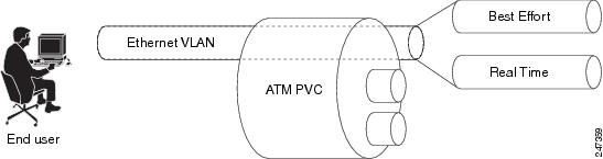
VLAN-based service differentiation allows service providers to offer a range of broadband-enabled services and applications to end users. It supports IP connectivity applications that require real-time network performance and applications that use best-effort, or Internet-grade, performance.
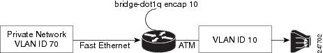
The original VLAN tag in an inbound packet is changed to the value configured by the bridge-dot1q encap command before the tag leaves the router. For example, if you enter the command bridge-dot1q encap 10, a VLAN tag of 70 in a packet inbound from the local network is changed to a value of 10 in the egress packet. Any 802.1P value is changed to 0, and frames without VLAN tags are sent out over ATM with an added VLAN header as shown in Figure 3.
From an Ethernet perspective, this service is carried over a dedicated VLAN from the hand-over point to the end-user premises. This VLAN-based service differentiation at PVC level is shown in Figure 1.
Figure 1 VLAN-Based Service Differentiation at PVC Level
The Ethernet VLAN used by the voice, video, and data services must be identified at the customer premises by an 802.1Q VLAN ID configured using the bridge-dot1q encap command. The VLAN is identified at the service provider's end by a service-provider-assigned 802.1ad customer VLAN ID.
The bridge-dot1q encap command changes the local VLAN ID to the VLAN ID required by the service provider. The operation of this command is shown in Figure 2.
Figure 2 Operation of the bridge-dot1q encap Command
Figure 3 and Figure 4 show the PDU data structure in greater detail.
Transporting 802.1P Marked 802.1Q Tags
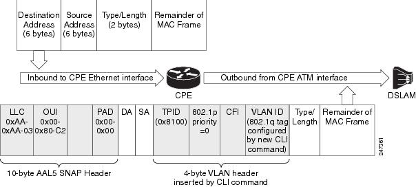
An 802.1Q VLAN tag is inserted into the MAC Protocol Data Unit (PDU), and this PDU is sent to the Digital Subscriber Line Access Multiplexer (DSLAM). Incoming and outgoing PDU structures are shown in Figure 3 and in Figure 4.
Figure 3 shows the packet structure when the incoming Ethernet frames do not have a VLAN header.
Figure 3 Incoming and Outgoing Packet Structures When No Incoming VLAN ID Is Present
Figure 3 shows that a 4-byte VLAN header has been inserted in the outgoing packet, with an 802.1P value. The VLAN ID value is configured by the bridge-dot1q encap command.
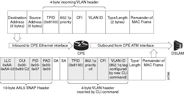
Figure 4 shows the incoming packet structure when the incoming Ethernet packets contain a VLAN header.
Figure 4 Incoming and Outgoing Packet Structures When an Incoming VLAN ID Is Present
The outgoing packet structure is the same as in Figure 3.
Note
The CPE is connected to the DSLAM via an ATM interface that is configured as the bridging interface. The CPE establishes a PPP over Ethernet (PPPoE) session over the bridging ATM interface with the service provider. The VLAN and voice traffic enter customer devices via VLAN ports or a Switched Virtual Interface (SVI).
In the CPE, the packet is classified as data or voice traffic based on the VLAN ID, Differentiated Services Code Point (DSCP), protocol, source MAC address, or port. The packets are marked with the quality of service (QoS) group, and routed from VLAN via the Bridge Virtual Interface (BVI) to the ATM PVC bridging interface.
If the packet requires encapsulation, ATM provides the default VLAN ID. If there is a QoS service policy attached to the PVC, packets are classified against the QoS group. QoS marks the corresponding VLAN ID and 802.1P or CoS value into the packet VLAN header. The QoS VLAN ID overwrites the default VLAN ID. If there is no service policy attached in PVC, the packets are sent out with the default VLAN ID and default CoS marking.
Packets returning from the service provider's network and destined to the customer's network carry VLAN tags. The ATM PVC interface removes the VLAN tag before passing it for further processing. These packets do not require classification or QoS marking.
Using PPPoE, the CPE device acts as a PPPoE Dialer client and gets the IP address dynamically from the service provider using the Point-to-Point Protocol. The Dialer interface has to be configured and associated with the ATM PVC interface. The packets are sent out with the default VLAN ID as PPPoE supports only one VLAN ID per PVC. PPP control packets such as PPPoE Active Discovery Initiation (PADI), PPPoE Active Discovery Request (PADR), PPPoE Active Discovery Terminate (PADT) and keepalive packets are marked with higher priority CoS markings similar to the real-time traffic. The VLAN header has to be removed from the packet at the ingress interface (ATM PVC) when the packet returns.
Benefits of Preserve 802.1Q Tagging with 802.1P Marking over ATM PVCs for xDSL Uplinks Feature
This feature offers the following benefits:
•
•
•
How to Configure the Preserve 802.1Q Tagging with 802.1P Marking over ATM PVCs for xDSL Uplinks Feature
Perform this task to configure the Preserve 802.1Q Tagging with 802.1P Marking over ATM PVCs for xDSL Uplinks feature.
Restrictions
Only one bridge-dot1q encap vlan-id command can be configured under a PVC. Only one VLAN ID is allowed per session using PPPoE. The PPPoE session can be disconnected if the configured VLAN ID (set using the set vlan-inner or bridge-dot1q encap vlanid command) differs from the default VLAN ID.
SUMMARY STEPS
1.
2.
3.
4.
5.
6.
7.
8.
9.
10.
11.
12.
13.
14.
15.
16.
17.
18.
19.
20.
21.
22.
23.
DETAILED STEPS
Troubleshooting Tips
You need to verify that the bridge-dot1q encap and encapsulation aal5snap commands are configured to carry the tagged VLAN traffic if the 802.1P marked 802.1Q tags are not transported in the MAC PDUs sent to the DSLAM.
Configuration Examples for Preserve 802.1Q Tagging with 802.1P Marking over ATM PVCs for xDSL Uplinks
This section provides the following configuration examples:
•
•
Example: Traffic from Multiple Incoming VLANs Bridged to a Single Outgoing VLAN
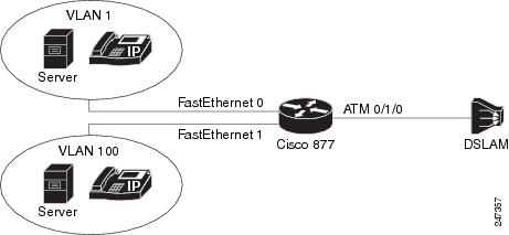
This example shows how the traffic from multiple incoming VLANs is bridged to a single outgoing VLAN. The traffic is arriving on Layer-2 Fast Ethernet ports, and a DHCP server assigns IP addresses on the private network. Network Address Translation (NAT) is enabled. A static IP address is used on the outgoing Bridge-Group Virtual Interface (BVI) interface.
This topology is shown in Figure 5.
Figure 5 Topology: Traffic from Multiple Incoming VLANs Bridged to a Single Outgoing VLAN
The following configuration is for the Cisco 877 router.
ip dhcp excluded-address 192.168.10.1ip dhcp excluded-address 192.168.20.1!ip dhcp pool test_pool1network 192.168.10.0 255.255.255.0default-router 192.168.10.1!ip dhcp pool test_pool2network 192.168.20.0 255.255.255.0default-router 192.168.20.1!!bridge irb!!interface ATM0no ip addressno atm ilmi-keepalive!interface ATM0.1 point-to-pointbridge-group 1bridge-group 1 spanning-disabledpvc 0/110bridge-dot1q encap 10encapsulation aal5snap!interface FastEthernet0switchport access vlan 1!interface FastEthernet1switchport access vlan 100!interface Vlan1ip address 192.168.10.1 255.255.255.0ip nat insideip virtual-reassembly!interface Vlan100ip address 192.168.20.1 255.255.255.0ip nat insideip virtual-reassembly!interface BVI1ip address 12.0.0.1 255.0.0.0ip nat outsideip virtual-reassembly!ip forward-protocol ndip route 0.0.0.0 0.0.0.0 12.0.0.2ip nat pool test 12.0.0.1 12.0.0.1 netmask 255.0.0.0ip nat inside source list 101 pool test overloadip nat inside source list 102 pool test overload!access-list 101 permit ip 192.168.10.0 0.0.0.255 any logaccess-list 102 permit ip 192.168.20.0 0.0.0.255 any log!bridge 1 protocol ieeebridge 1 route ip!Example: Traffic from Multiple VLANs Arrive at Router over Layer-3 Port
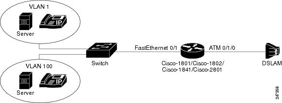
This example shows how traffic from multiple VLANs arrive at the router over a Layer-3 port. All this traffic is bridged over a single ATM virtual circuit to the service provider's DSLAM and tagged with a single VLAN tag. Both WAN and LAN IP addresses are provided by DHCP servers.
This topology is shown in Figure 6.
Figure 6 Topology: Traffic From Multiple VLANs Arrive at Router over Layer-3 Port
The following configuration is for the Cisco 877 router.
ip dhcp excluded-address 192.168.10.1ip dhcp excluded-address 192.168.20.1!ip dhcp pool test_pool1network 192.168.10.0 255.255.255.0default-router 192.168.10.1!ip dhcp pool test_pool2network 192.168.20.0 255.255.255.0default-router 192.168.20.1!bridge irb!!interface FastEthernet0/1no ip addressduplex autospeed auto!interface FastEthernet0/1.1encapsulation dot1Q 100ip address 192.168.10.1 255.255.255.0ip nat insideip virtual-reassembly!interface FastEthernet0/1.2encapsulation dot1Q 1 nativeip address 192.168.20.1 255.255.255.0ip nat insideip virtual-reassembly!interface ATM0/1/0no ip addressno atm ilmi-keepalive!!interface ATM0/1/0.1 point-to-pointbridge-group 1bridge-group 1 spanning-disabledpvc 9/117bridge-dot1q encap 10encapsulation aal5snap!!interface BVI1ip address dhcpip nat outsideip virtual-reassembly!ip forward-protocol nd!ip nat inside source list 101 interface BVI1 overloadip nat inside source list 102 interface BVI1 overload!access-list 101 permit ip 192.168.10.0 0.0.0.255 any logaccess-list 102 permit ip 192.168.20.0 0.0.0.255 any log!bridge 1 protocol ieeebridge 1 route ipAdditional References
Related Documents
ATM commands: complete command syntax, command mode, command history, usage guidelines, and examples.
Standards
MIBs
None
To locate and download MIBs for selected platforms, Cisco IOS releases, and feature sets, use Cisco MIB Locator found at the following URL:
RFCs
Technical Assistance
Feature Information for Preserve 802.1Q Tagging with 802.1P Marking over ATM PVCs for xDSL Uplinks
Table 2 lists the features in this module and provides links to specific configuration information.
Use Cisco Feature Navigator to find information about platform support and software image support. Cisco Feature Navigator enables you to determine which software images support a specific software release, feature set, or platform. To access Cisco Feature Navigator, go to http://www.cisco.com/go/cfn. An account on Cisco.com is not required.
Note
Glossary
802.1ad—An amendment to IEEE 802.1Q that enables a service provider to offer bridged VLANs over its network.
802.1P—A 3-bit field within an Ethernet frame header when using IEEE 802.1Q on an IEEE 802.1D network. It specifies a priority value of between 0 and 7 inclusive that can be used by quality of service (QoS) disciplines to differentiate traffic.
802.1Q—A networking standard written by the IEEE 802.1 workgroup allowing multiple bridged networks to transparently share the same physical network link without leakage of information between networks. 802.1Q is commonly referred to as VLAN tagging.
AAL5SNAP—ATM Adaptation Layer 5 Subnetwork Protocol Access Protocol. A type of network encapsulation that supports multiplexing of two or more protocols over a virtual circuit.
ATM—Asynchronous Transfer Mode. The international standard for cell relay in which multiple service types (such as voice, video, or data) are conveyed in fixed-length (53-byte) cells. Fixed-length cells allow cell processing to occur in hardware, thereby reducing transit delays. ATM is designed to take advantage of high-speed transmission media, such as E3, SONET, and T3.
BVI—Bridge Group Virtual Interface. Logical Layer 3-only interface associated with a bridge group when IRB is configured.
CPE—customer premises equipment. Terminating equipment, such as terminals, telephones, and modems, supplied by the telephone company, installed at customer sites, and connected to the telephone company network. This term can also refer to any telephone equipment residing on the customer site.
CVLAN—Customer Virtual Local Area Network.
DSL—digital subscriber line. Public network technology that delivers high bandwidth over conventional copper wiring at limited distances. There are four types of DSL: ADSL, HDSL, SDSL, and VDSL.
DSLAM—digital subscriber line access multiplexer. A device that connects many digital subscriber lines to a network by multiplexing the DSL traffic onto one or more network trunk lines.
IRB—integrated routing and bridging. Integrated Services Digital Network (ISDN) User Part. An upper-layer application supported by Signalling System 7 for connection set up and tear down.
NAT—Network Address Translation. Mechanism for reducing the need for globally unique IP addresses. NAT allows an organization with addresses that are not globally unique to connect to the Internet by translating those addresses into globally routable address space. Also known as Network Address Translator.
PVC—permanent virtual circuit (or connection). A virtual circuit that is permanently established. PVCs save bandwidth associated with circuit establishment and tear down in situations where certain virtual circuits must exist all the time. In ATM terminology, this is called a permanent virtual connection.
VoIP—Voice over IP. The capability to carry normal telephony-style voice over an IP-based internet with POTS-like functionality, reliability, and voice quality.
Cisco and the Cisco Logo are trademarks of Cisco Systems, Inc. and/or its affiliates in the U.S. and other countries. A listing of Cisco's trademarks can be found at www.cisco.com/go/trademarks. Third party trademarks mentioned are the property of their respective owners. The use of the word partner does not imply a partnership relationship between Cisco and any other company. (1005R)
Any Internet Protocol (IP) addresses and phone numbers used in this document are not intended to be actual addresses and phone numbers. Any examples, command display output, network topology diagrams, and other figures included in the document are shown for illustrative purposes only. Any use of actual IP addresses or phone numbers in illustrative content is unintentional and coincidental.
©2009-2010 Cisco Systems, Inc. All rights reserved.