Feedback
Table Of Contents
Configuring Token Ring LAN Emulation for Multiprotocol over ATM
Token Ring LANE for MPOA Configuration Task List
Token Ring LANE Configuration Examples
MPOA Token Ring LANE Configuration in an IP-Routed Domain Example
MPOA Token Ring LANE Configuration in an IP SRB-Routed Domain Example
Configuring Token Ring LAN Emulation for Multiprotocol over ATM
This chapter describes the required and optional tasks for configuring the MPOA for Token Ring Networks feature.
For a complete description of the commands in this chapter, refer to the the Cisco IOS Switching Services Command Reference. To locate documentation of other commands that appear in this chapter, use the command reference master index or search online.
To identify the hardware platform or software image information associated with a feature, use the Feature Navigator on Cisco.com to search for information about the feature or refer to the software release notes for a specific release. For more information, see the section "Identifying Supported Platforms" in the chapter "Using Cisco IOS Software."
The MPOA for Token Ring Networks feature allows Token Ring hosts on an ATM network to communicate over direct paths (called shortcuts) through the ATM network. These shortcuts bypass the intermediate router hops that otherwise would be encountered in the default path.
How Token Ring MPOA Works
Token Ring Multiprotocol over ATM (MPOA) is an extension to LAN Emulation (LANE). It allows Token Ring LANE clients to forward IP packets between subnets to other Token Ring LANE clients through a shortcut in the ATM network. The Token Ring LANE clients have an MPOA client (MPC) communicating with an MPOA server (MPS) to establish this shortcut.
Token Ring LANE for MPOA Configuration Task List
To configure Token Ring LANE for MPOA, perform the tasks described in the following sections:
•
Configuring the LECS Database
Configuring a Token Ring LEC
For MPOA operation, a LEC must be associated with an MPS, an MPC, or both. Once a LEC is bound to a particular MPS/MPC, it cannot be bound to another MPS/MPC at the same time.
The LEC must also be associated with a physical interface or subinterface, which may be different from the physical interface associated with the MPS or MPC. For proper operation, all interfaces must belong to the same ATM network.
To configure a Token Ring LEC, use the following commands beginning in global configuration mode:
Configuring the LECS Database
To configure the LECS database, use the following commands in beginning global configuration mode:
Configuring the LES/BUS
To configure the LES/BUS, use the following commands in beginning global configuration mode:
Token Ring LANE Configuration Examples
This section provides the following sample configurations of MPOA in a Token Ring LANE environment:
•
•
MPOA Token Ring LANE Configuration in an IP-Routed Domain Example
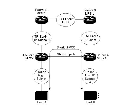
Figure 36 illustrates MPOA in a Token Ring LANE environment where MPC-to-MPC shortcuts are established between Token Ring LANE edge routers that reside in different IP-routed domains.
Figure 36 Token Ring MPOA—MPC to MPC Shortcut in an IP Routed Environment
The following commands show a sample configuration for Router-1 in Figure 36:
hostname Router-1!ip routing!! Define the MPOA Client (mpc-1) configuration.!mpoa client config name mpc-1!! Configure an IP address on the Token Ring interface.!interface TokenRing1/0ip address 5.5.5.2 255.255.255.0ring-speed 16!! Configure a config-server and bind it to its database (mpoa-db).! Attach the MPOA client mpc-1 to its ATM interface.!interface ATM2/0no ip addressatm pvc 1 0 5 qsaalatm pvc 2 0 16 ilmilane config auto-config-atm-addresslane config database mpoa-dbmpoa client name mpc-1!! Configure a LANE server-bus and LANE client on ELAN 1. Bind the! LANE client to its MPOA Client (mpc-1).!interface ATM2/0.1 multipointip address 1.1.1.1 255.255.255.0lane server-bus tokenring 1lane client mpoa client name mpc-1lane client tokenring 1!router eigrp 1network 1.0.0.0network 5.0.0.0!endThe following commands show a sample configuration for Router-2 in Figure 36:
hostname Router-2!ip routing!! Configure the config-server database mpoa-db with configuration! for ELANs 1 to 3!lane database mpoa-dbname 1 server-atm-address 47.0091810000000060705BFA01.00000CA05F41.01name 1 local-seg-id 1000name 1 elan-id 100name 2 server-atm-address 47.0091810000000060705BFA01.00000CA05B41.01name 2 local-seg-id 2000name 2 elan-id 200name 3 server-atm-address 47.0091810000000060705BFA01.00000CA05B41.03name 3 local-seg-id 3000name 3 elan-id 300!! Define the MPOA Server (mps-1) configuration.mpoa server config name mps-1!! Configure the signalling and ILMI PVCs. Also configure a config-server! and attach the MPOA server (mps-1) to its ATM interface.!interface ATM4/0no ip addressatm pvc 1 0 5 qsaalatm pvc 2 0 16 ilmilane config auto-config-atm-addresslane config database mpoa-dbmpoa server name mps-1!! Configure a Token Ring LANE client on ELAN 1 and bind the LANE! client to its MPOA server (mps-1).!interface ATM4/0.1 multipointip address 1.1.1.2 255.255.255.0lane client mpoa server name mps-1lane client tokenring 1!! Configure a Token Ring LANE client on ELAN 2 and bind the LANE! client to its MPOA server (mps-1)!interface ATM4/0.2 multipointip address 2.2.2.1 255.255.255.0lane client mpoa server name mps-1lane client tokenring 2!router eigrp 1network 1.0.0.0network 2.0.0.0!endThe following commands show a sample configuration for Router-3 in Figure 36:
hostname Router-3!ip routing!! Defines the MPOA Server (mps-2) configuration.mpoa server config name mps-2!! Configure the signalling and ILMI PVCs and attach the MPOA! server (mps-2) to its ATM interface.!interface ATM2/0no ip addressatm pvc 1 0 5 qsaalatm pvc 2 0 16 ilmimpoa server name mps-2!! Configure a Token Ring LANE client and LANE server-bus on ELAN 2! and bind the LANE client to its MPOA server (mps-2)!interface ATM2/0.1 multipointip address 2.2.2.2 255.255.255.0lane server-bus tokenring 2lane client mpoa server name mps-2lane client tokenring 2!! Configure a Token Ring LANE client on ELAN 3 and bind the LANE! client to its MPOA server (mps-2)!interface ATM2/0.3 multipointip address 3.3.3.1 255.255.255.0lane server-bus tokenring 3lane client mpoa server name mps-2lane client tokenring 3!router eigrp 1network 2.0.0.0network 3.0.0.0!endThe following commands show a sample configuration for Router-4 in Figure 36:
hostname Router-4!ip routing!! Define the MPOA client (mpc-2) configuration.!mpoa client config name mpc-2!! Configure the Token Ring interface!interface TokenRing1/0ip address 4.4.4.1 255.255.255.0ring-speed 16!! Configure the signalling and ILMI PVCs and attach the MPOA! client to its ATM interface.!interface ATM2/0atm pvc 1 0 5 qsaalatm pvc 2 0 16 ilmimpoa client name mpc-2!! Configure a Token Ring LANE client on ELAN 3 and bind the LANE! client to its MPOA client (mpc-2).!interface ATM2/0.1 multipointip address 3.3.3.2 255.255.255.0lane client mpoa client name mpc-2lane client tokenring 3!router eigrp 1network 3.0.0.0network 4.0.0.0!endMPOA Token Ring LANE Configuration in an IP SRB-Routed Domain Example
Figure 37 illustrates MPOA in a Token Ring LANE environment where MPC-to-MPC shortcuts are established between a Token Ring LANE edge device and a Token Ring LANE router that reside in an IP SRB domain and IP-routed domains.
Figure 37 Token Ring MPOA—MPC to MPC Shortcut in an IP SRB-Routed Environment
The following commands show a sample configuration for Router-1 in Figure 37:
hostname Router-1!ip routing!! Configure the config-server database mpoa-db with configuration! for ELANs 1 to 3lane database mpoa-dbname 1 server-atm-address 47.0091810000000060705BFA01.00000CA05F41.01name 1 local-seg-id 1000name 1 elan-id 100name 2 server-atm-address 47.0091810000000060705BFA01.00000CA05B41.01name 2 local-seg-id 2000name 2 elan-id 200name 3 server-atm-address 47.0091810000000060705BFA01.00000CA05B41.03name 3 local-seg-id 3000name 3 elan-id 300!! Define the MPOA Server (mps-1) configuration.mpoa server config name mps-1!! Configure the signalling and ILMI PVCs. Also configure a config-server! and attach the MPOA server (mps-1) to its ATM interface.interface ATM4/0no ip addressatm pvc 1 0 5 qsaalatm pvc 2 0 16 ilmilane config auto-config-atm-addresslane config database mpoa-dbmpoa server name mps-1!! Configure a Token Ring LANE client on ELAN 1 and bind the LANE! client to its MPOA server (mps-1). The multiring ip configuration! is required to terminate the RIF for IP packets on the ELAN.interface ATM4/0.1 multipointip address 1.1.1.2 255.255.255.0lane client mpoa server name mps-1lane client tokenring 1multiring ip!! Configure a Token Ring LANE client on ELAN 2 and bind the LANE! client to its MPOA server (mps-1)!interface ATM4/0.2 multipointip address 2.2.2.1 255.255.255.0lane client mpoa server name mps-1lane client tokenring 2!!router eigrp 1network 1.0.0.0network 2.0.0.0!endThe following commands show a sample configuration for Router-2 in Figure 37:
hostname Router-2!ip routing!! Defines the MPOA Server (mps-2) configuration.mpoa server config name mps-2!!! Configure the signalling and ILMI PVCs and attach the MPOA! server (mps-2) to its ATM interface.interface ATM2/0no ip addressatm pvc 1 0 5 qsaalatm pvc 2 0 16 ilmimpoa server name mps-2!! Configure a Token Ring LANE client and LANE server-bus on ELAN 2! and bind the LANE client to its MPOA server (mps-2)!interface ATM2/0.1 multipointip address 2.2.2.2 255.255.255.0lane server-bus tokenring 2lane client mpoa server name mps-2lane client tokenring 2!! Configure a Token Ring LANE client on ELAN 3 and bind the LANE! client to its MPOA server (mps-2)!interface ATM2/0.3 multipointip address 3.3.3.1 255.255.255.0lane server-bus tokenring 3lane client mpoa server name mps-2lane client tokenring 3!router eigrp 1network 2.0.0.0network 3.0.0.0!endThe following commands show a sample configuration for Router-3 in Figure 37:
hostname Router-3!ip routing!! Define the MPOA client (mpc-2) configuration.mpoa client config name mpc-2!!! Configure the Token Ring interfaceinterface TokenRing1/0ip address 4.4.4.1 255.255.255.0ring-speed 16!! Configure the signalling and ILMI PVCs and attach the MPOA! client to its ATM interface.!interface ATM2/0atm pvc 1 0 5 qsaalatm pvc 2 0 16 ilmimpoa client name mpc-2!! Configure a Token Ring LANE client on ELAN 3 and bind the LANE! client to its MPOA client (mpc-2).!interface ATM2/0.1 multipointip address 3.3.3.2 255.255.255.0lane client mpoa client name mpc-2lane client tokenring 3!router eigrp 1network 3.0.0.0network 4.0.0.0!end
Any Internet Protocol (IP) addresses used in this document are not intended to be actual addresses. Any examples, command display output, and figures included in the document are shown for illustrative purposes only. Any use of actual IP addresses in illustrative content is unintentional and coincidental.
© 2007 Cisco Systems, Inc. All rights reserved.