Feedback
Table Of Contents
LANE Implementation Considerations
Method of Automatically Assigning ATM Addresses
Rules for Assigning Components to Interfaces and Subinterfaces
Creating a LANE Plan and Worksheet
Configuring the Prefix on the Switch
Setting Up the Signalling and ILMI PVCs
Displaying LANE Default Addresses
Entering the LECS's ATM Address on the Cisco Switch
Entering the ATM Addresses on the Cisco LightStream 1010 ATM Switch
Entering the ATM Addresses on the Cisco LightStream 100 ATM Switch
Setting Up the LECS's Database
Setting Up the Database for the Default ELAN Only
Setting Up the Database for Unrestricted-Membership Emulated LANs
Setting Up the Database for Restricted-Membership LANs
Setting Up the Server, BUS, and a Client on a Subinterface
Setting Up Only a Client on a Subinterface
Disabling the LE_FLUSH Process of LAN Emulation Clients
Setting Up LANE Clients for MPOA
Configuring Fault-Tolerant Operation
Simple Server Redundancy Requirements
Fast Simple Server Redundancy Requirements
Redundant Configuration Servers
SSRP Changes to Reduce Network Flap
Monitoring and Maintaining the LANE Components
Default Configuration for a Single Ethernet ELAN Example
Default Configuration for a Single Ethernet ELAN with a Backup LECS and LES Example
Multiple Token Ring ELANs with Unrestricted Membership Example
Multiple Token Ring ELANs with Restricted Membership Example
TR-LANE with 2-Port SRB Example
TR-LANE with Multiport SRB Example
Routing Between Token Ring and Ethernet Emulated LANs Example
Disabling LANE Flush Process Example
Configuring LAN Emulation
This chapter describes how to configure LAN emulation (LANE) on the following platforms that are connected to an ATM switch or switch cloud:
•
ATM Interface Processor (AIP) on the Cisco 7500 series routers
•
•
Note
This chapter contains these sections:
•
For a complete description of the commands in this chapter, refer to the the Cisco IOS Switching Services Command Reference. To locate documentation of other commands that appear in this chapter, use the command reference master index or search online.
To identify the hardware platform or Cisco IOS image information associated with a feature, use the Feature Navigator on Cisco.com to search for information about the feature or refer to the Cisco IOS release notes for a specific release. For more information, see the section "Identifying Supported Platforms" in the chapter "Using Cisco IOS Software."
LANE on ATM
LANE emulates an IEEE 802.3 Ethernet or IEEE 802.5 Token Ring LAN using ATM technology. LANE provides a service interface for network-layer protocols that is identical to existing MAC layers. No changes are required to existing upper layer protocols and applications. With LANE, Ethernet and Token Ring packets are encapsulated in the appropriate ATM cells and sent across the ATM network. When the packets reach the other side of the ATM network, they are deencapsulated. LANE essentially bridges LAN traffic across ATM switches.
Benefits of LANE
ATM is a cell-switching and multiplexing technology designed to combine the benefits of circuit switching (constant transmission delay and guaranteed capacity) with those of packet switching (flexibility and efficiency for intermittent traffic).
LANE allows legacy Ethernet and Token Ring LAN users to take advantage of ATM's benefits without modifying end-station hardware or software. ATM uses connection-oriented service with point-to-point signalling or multicast signalling between source and destination devices. However, LANs use connectionless service. Messages are broadcast to all devices on the network. With LANE, routers and switches emulate the connectionless service of a LAN for the endstations.
By using LANE, you can scale your networks to larger sizes while preserving your investment in LAN technology.
LANE Components
A single emulated LAN (ELAN) consists of the following entities: A LECS, a BUS, a LES, and LANE clients.
•
•
•
•
ELAN entities coexist on one or more Cisco routers. On Cisco routers, the LES and the BUS are combined into a single entity.
Other LANE components include ATM switches—any ATM switch that supports the Interim Local Management Interface (ILMI) and signalling. Multiple emulated LANs can coexist on a single ATM network.
Simple Server Redundancy
LANE relies on three servers: the LECS, the LES, and the BUS. If any one of these servers fails, the ELAN cannot fully function.
Cisco has developed a fault tolerance mechanism known as simple server redundancy that eliminates these single points of failure. Although this scheme is proprietary, no new protocol additions have been made to the LANE subsystems.
Simple server redundancy uses multiple LECSs and multiple broadcast-and-unknown and LESs. You can configure servers as backup servers, which will become active if a master server fails. The priority levels for the servers determine which servers have precedence.
Refer to the "Configuring Fault-Tolerant Operation" section for details and notes on the Simple Server Redundancy Protocol (SSRP).
LANE Implementation Considerations
The following sections contain information relevant to implementation:
•
•
•
•
Network Support
In this release, Cisco supports the following networking features:
•
–
–
–
•
–
–
–
–
–
–
–
Cisco's implementation of LAN Emulation over 802.5 uses existing terminology and configuration options for Token Rings, including SRB. For more information about configuring SRB, see the chapter "Configuring Source-Route Bridging" in the Cisco IOS Bridging and IBM Networking Configuration Guide. Transparent bridging and Advanced Peer-to-Peer Networking (APPN) are not supported at this time.
•
For information about configuring APPN over Ethernet LANE, refer to the "Configuring APPN" chapter in the Cisco IOS Bridging and IBM Networking Configuration Guide.
Hardware Support
This release of LANE is supported on the following platforms:
•
•
•
Note
The router must contain an ATM Interface Processor (AIP), ATM port adapter, or an NP-1A ATM Network Processor Module (NPM). These modules provide an ATM network interface for the routers. Network interfaces reside on modular interface processors, which provide a direct connection between the high-speed Cisco Extended Bus (CxBus) and the external networks. The maximum number of AIPs, ATM port adapters, or NPMs that the router supports depends on the bandwidth configured. The total bandwidth through all the AIPs, ATM port adapters, or NPMs in the system should be limited to 200 Mbps full duplex—two Transparent Asynchronous Transmitter/Receiver Interfaces (TAXIs), one Synchronous Optical Network (SONET) and one E3, or one SONET and one lightly used SONET.
This feature also requires one of the following switches:
•
•
•
TR-LANE requires Cisco IOS Release 3.1(2) or later on the LightStream 100 switch and Cisco IOS Release 11.1(8) or later on the LightStream 1010.
For a complete description of the routers, switches, and interfaces, refer to your hardware documentation.
Addressing
On a LAN, packets are addressed by the MAC-layer address of the destination and source stations. To provide similar functionality for LANE, MAC-layer addressing must be supported. Every LANE client must have a MAC address. In addition, every LANE component (server, client, BUS, and LECS) must have an ATM address that is different from that of all the other components.
All LANE clients on the same interface have the same, automatically assigned MAC address. That MAC address is also used as the end-system identifier (ESI) part of the ATM address, as explained in the next section. Although client MAC addresses are not unique, all ATM addresses are unique.
LANE ATM Addresses
A LANE ATM address has the same syntax as an NSAP, but it is not a network-level address. It consists of the following:
•
–
–
–
–
–
–
–
•
•
Method of Automatically Assigning ATM Addresses
We provide the following standard method of constructing and assigning ATM and MAC addresses for use in a LECS's database. A pool of MAC addresses is assigned to each ATM interface on the router. On the Cisco 7200 series routers, Cisco 7500 series routers, Cisco 4500 routers, and Cisco 4700 routers, the pool contains eight MAC addresses. For constructing ATM addresses, the following assignments are made to the LANE components:
•
•
•
•
•
•
Because the LANE components are defined on different subinterfaces of an ATM interface, the value of the selector field in an ATM address is different for each component. The result is a unique ATM address for each LANE component, even within the same router. For more information about assigning components to subinterfaces, see the "Rules for Assigning Components to Interfaces and Subinterfaces" section later in this chapter.
For example, if the MAC addresses assigned to an interface are 0800.200C.1000 through 0800.200C.1007, the ESI part of the ATM addresses is assigned to LANE components as follows:
•
•
•
•
Refer to the "Multiple Token Ring ELANs with Unrestricted Membership Example" and the "Multiple Token Ring ELANs with Restricted Membership Example" sections for examples using MAC address values as ESI field values in ATM addresses and for examples using subinterface numbers as selector field values in ATM addresses.
Using ATM Address Templates
ATM address templates can be used in many LANE commands that assign ATM addresses to LANE components (thus overriding automatically assigned ATM addresses) or that link client ATM addresses to emulated LANs. The use of templates can greatly simplify the use of these commands. The syntax of address templates, the use of address templates, and the use of wildcard characters within an address template for LANE are very similar to those for address templates of ISO CLNS.
Note
LANE ATM address templates can use two types of wildcards: an asterisk (*) to match any single character, and an ellipsis (...) to match any number of leading or trailing characters.
In LANE, a prefix template explicitly matches the prefix but uses wildcards for the ESI and selector fields. An ESI template explicitly matches the ESI field but uses wildcards for the prefix and selector. Table 14 indicates how the values of unspecified digits are determined when an ATM address template is used:
Table 14 Values of Unspecified Digits in ATM Address Templates
Prefix (first 13 bytes)
Obtained from ATM switch via Interim Local Management Interface (ILMI)
ESI (next 6 bytes)
Filled with the slot MAC address1 plus
•
•
•
•
Selector field (last 1 byte)
Subinterface number, in the range 0 through 255.
1 The lowest of the pool of MAC addresses assigned to the ATM interface plus a value that indicates the LANE component. For the Cisco 7200 series routers, Cisco 7500 series routers, Cisco 4500 routers, and Cisco 4700 routers, the pool has eight MAC addresses.
Rules for Assigning Components to Interfaces and Subinterfaces
The following rules apply to assigning LANE components to the major ATM interface and its subinterfaces in a given router:
•
The assignment of any other component to the major interface is identical to assigning that component to the 0 subinterface.
•
•
•
LANE Configuration Task List
Before you begin to configure LANE, you must decide whether you want to set up one or multiple emulated LANs. If you set up multiple emulated LANs, you must also decide where the servers and clients will be located, and whether to restrict the clients that can belong to each ELAN. Bridged emulated LANs are configured just like any other LAN, in terms of commands and outputs. Once you have made those basic decisions, you can proceed to configure LANE.
To configure LANE, perform the tasks described in the following sections:
•
•
•
•
•
•
Once LANE is configured, you can configure Multiprotocol over ATM (MPOA). For MPOA to work with LANE, a LANE client must have an ELAN ID to work properly, a LANE client must have an ELAN ID. To set up a LANE client for MPOA and give an ELAN ID perform the tasks described in the following section:
•
Although the sections described contain information about configuring SSRP fault tolerance, refer to the "Configuring Fault-Tolerant Operation" section for detailed information about requirements and implementation considerations.
Once LANE is configured, you can monitor and maintain the components in the participating routers by completing the tasks described in the "Monitoring and Maintaining the LANE Components" section.
For configuration examples, see the "LANE Configuration Examples" section at the end of this chapter.
Creating a LANE Plan and Worksheet
Draw up a plan and a worksheet for your own LANE scenario, showing the following information and leaving space for noting the ATM address of each of the LANE components on each subinterface of each participating router:
•
•
•
•
•
•
The last three items in this list are very important; they determine how you set up each ELAN in the LECS's database.
Configuring the Prefix on the Switch
Before you configure LANE components on any Cisco 7200 series router, Cisco 7500 series router, Cisco 4500 router, or Cisco 4700 router, you must configure the Cisco ATM switch with the ATM address prefix to be used by all LANE components in the switch cloud. On the Cisco switch, the ATM address prefix is called the node ID. Prefixes must be 26 digits long. If you provide fewer than 26 digits, zeros are added to the right of the specified value to fill it to 26 digits.
To set the ATM address prefix on the Cisco LightStream 1010 Switch, use the following commands on the switch beginning in global configuration mode:
To set the ATM address prefix on the Cisco LightStream 100, use the following commands on the Cisco switch:
On the switches, you can display the current prefix by using the show network EXEC command.
Note
Setting Up the Signalling and ILMI PVCs
You must set up the signalling permanent virtual circuit (PVC) and the PVC that will communicate with the ILMI on the major ATM interface of any router that participates in LANE.
Complete this task only once for a major interface. You do not need to repeat this task on the same interface even though you might configure LESs and clients on several of its subinterfaces.
To set up these PVCs, use the following commands beginning in global configuration mode:
Displaying LANE Default Addresses
You can display the LANE default addresses to make configuration easier. Complete this task for each router that participates in LANE. This command displays default addresses for all ATM interfaces present on the router. Write down the displayed addresses on your worksheet.
To display the default LANE addresses, use the following command in EXEC mode:
Entering the LECS's ATM Address on the Cisco Switch
You must enter the LECS's ATM address into the Cisco LightStream 100 or Cisco Lightstream 1010 ATM switch and save it permanently so that the value is not lost when the switch is reset or powered off.
You must specify the full 40-digit ATM address. Use the addresses on your worksheet that you obtained from the previous task.
If you are configuring SSRP or Fast Simple Server Redundancy Protocol (FSSRP), enter the multiple LECS addresses into the end ATM switches. The switches are used as central locations for the list of LECS addresses. LANE components connected to the switches obtain the global list of LECS addresses from the switches.
Depending on which type of switch you are using, perform one of the tasks in the following sections:
•
•
Entering the ATM Addresses on the Cisco LightStream 1010 ATM Switch
On the Cisco LightStream 1010 ATM switch, the LECS address can be specified for a port or for the entire switch.
To enter the LECS addresses on the Cisco LightStream 1010 ATM switch for the entire switch, use the following commands beginning in global configuration mode:
Step 1
Router(config)# atm lecs-address-default lecsaddress [sequence #]1
Specifies the LECS's ATM address for the entire switch. If you are configuring SSRP, include the ATM addresses of all the LECSs.
Step 2
Router(config)# exit
Exits global configuration mode.
Step 3
Router# copy system:running-config nvram:startup-config
Saves the configuration value permanently.
1 Refer to the LightStream 1010 ATM Switch Command Reference for further information about this command.
To enter the LECS addresses on the Cisco LightStream 1010 ATM switch per port, use the following commands beginning in interface configuration mode:
Step 1
Router(config-if)# atm lecs-address lecsaddress [sequence #]1
Specifies the LECS's ATM address for a port. If you are configuring SSRP, include the ATM addresses of all the LECSs.
Step 2
Router(config-if)# Ctrl-Z
Exits interface configuration mode.
Step 3
Router# copy system:running-config nvram:startup-config
Saves the configuration value permanently.
1 Refer to the LightStream 1010 ATM Switch Command Reference for further information about this command.
Entering the ATM Addresses on the Cisco LightStream 100 ATM Switch
To enter the LECS's ATM address into the Cisco LightStream 100 ATM switch and save it permanently, use the following commands in privileged EXEC mode:
Setting Up the LECS's Database
The LECS's database contains information about each ELAN, including the ATM addresses of the LESs.
You can specify one default ELAN in the database. The LECS will assign any client that does not request a specific ELAN to the default ELAN.
Emulated LANs are either restricted or unrestricted. The LECS will assign a client to an unrestricted ELAN if the client specifies that particular ELAN in its configuration. However, the LECS will only assign a client to a restricted ELAN if the client is specified in the database of the LECS as belonging to that ELAN. The default ELAN must have unrestricted membership.
If you are configuring fault tolerance, you can have any number of servers per ELAN. Priority is determined by entry order; the first entry has the highest priority, unless you override it with the index option.
To set up the database, complete the tasks in the following sections as appropriate for your ELAN plan and scenario:
•
•
•
Setting Up the Database for the Default ELAN Only
When you configure a router as the LECS for one default ELAN, you provide a name for the database, the ATM address of the LES for the ELAN, and a default name for the ELAN. In addition, you indicate that the LECS's ATM address is to be computed automatically.
When you configure a database with only a default unrestricted ELAN, you do not have to specify where the LANE clients are located. That is, when you set up the LECS's database for a single default ELAN, you do not have to provide any database entries that link the ATM addresses of any clients with the ELAN name. All of the clients will be assigned to the default ELAN.
To set up the LECS for the default ELAN, use the following commands beginning in global configuration mode:
In Step 2, enter the ATM address of the server for the specified ELAN, as noted in your worksheet and obtained in the "Displaying LANE Default Addresses" section.
You can have any number of servers per ELAN for fault tolerance. Priority is determined by entry order. The first entry has the highest priority unless you override it with the index option.
If you are setting up only a default ELAN, the elan-name value in Steps 2 and 3 is the same as the default ELAN name you provide in Step 4.
To set up fault-tolerant operation, see the "Configuring Fault-Tolerant Operation" section later in this chapter.
Setting Up the Database for Unrestricted-Membership Emulated LANs
When you set up a database for unrestricted emulated LANs, you create database entries that link the name of each ELAN to the ATM address of its server.
However, you may choose not to specify where the LANE clients are located. That is, when you set up the LECS's database, you do not have to provide any database entries that link the ATM addresses or MAC addresses of any clients with the ELAN name. The LECS will assign the clients to the emulated LANs specified in the client's configurations.
To configure a router as the LECS for multiple emulated LANs with unrestricted membership, use the following commands beginning in global configuration mode:
In the preceding steps, enter the ATM address of the server for the specified ELAN, as noted in your worksheet and obtained in the "Displaying LANE Default Addresses" section.
To set up fault-tolerant operation, see the "Configuring Fault-Tolerant Operation" section later in this chapter.
Setting Up the Database for Restricted-Membership LANs
When you set up the database for restricted-membership emulated LANs, you create database entries that link the name of each ELAN to the ATM address of its server.
However, you must also specify where the LANE clients are located. That is, for each restricted-membership ELAN, you provide a database entry that explicitly links the ATM address or MAC address of each client of that ELAN with the name of that ELAN.
The client database entries specify which clients are allowed to join the ELAN. When a client requests to join an ELAN, the LECS consults its database and then assigns the client to the ELAN specified in the LECS's database.
When clients for the same restricted-membership ELAN are located in multiple routers, each client's ATM address or MAC address must be linked explicitly with the name of the ELAN. As a result, you must configure as many client entries (at Steps 6 and 7, in the following procedure) as you have clients for emulated LANs in all the routers. Each client will have a different ATM address in the database entries.
To set up the LECS for emulated LANs with restricted membership, use the following commands beginning in global configuration mode:
To set up fault-tolerant operation, see the "Configuring Fault-Tolerant Operation" section later in this chapter.
Enabling the LECS
Once you have created the database, you can enable the LECS on the selected ATM interface and router by using the following commands beginning in global configuration mode:
Setting Up LESs and Clients
For each router that will participate in LANE, set up the necessary servers and clients for each ELAN; then display and record the server and client ATM addresses. Be sure to keep track of the router interface where the LECS will eventually be located.
You can set up servers for more than one ELAN on different subinterfaces or on the same interface of a router, or you can place the servers on different routers.
When you set up a server and BUS on a router, you can combine them with a client on the same subinterface, a client on a different subinterface, or no client at all on the router.
Where you put the clients is important because any router with clients for multiple emulated LANs can route frames between those emulated LANs.
Depending on where your clients and servers are located, perform one of the following tasks for each LANE subinterface.
•
•
Setting Up the Server, BUS, and a Client on a Subinterface
To set up the server, BUS, and (optionally) clients for an ELAN, use the following commands beginning in global configuration mode:
Step 1
Router(config)# interface atm slot/0.subinterface-number
Router(config)# interface atm slot/port-adapter/0.subinterface-number
Router(config)# interface atm number.subinterface-numberSpecifies the subinterface for the ELAN on this router.
•
•
•
Step 2
Router(config-if)# lane server-bus {ethernet | tokenring} elan-name
Enables a LES and a LANE BUS for the ELAN.
Step 3
Router(config-if)# lane client {ethernet | tokenring} [elan-name] [elan-id id]
(Optional) Enables a LANE client for the ELAN.
To participate in MPOA, configures the LES and a LANE BUS for the ELAN with the ELAN ID.
Step 4
Router(config-if)# ip address mask1
Provides a protocol address for the client.
Step 5
Router(config-if)# Ctrl-Z
Returns to EXEC mode.
Step 6
Router# copy system:running-config nvram:startup-config
Saves the configuration.
1 The command or commands depend on the routing protocol used. If you are using IPX or AppleTalk, see the relevant protocol chapter (IPX or AppleTalk) in the Cisco IOS AppleTalk and Novell IPX Configuration Guide for the commands to use.
If the ELAN in Step 3 is intended to have restricted membership, consider carefully whether you want to specify its name here. You will specify the name in the LECS's database when it is set up. However, if you link the client to an ELAN in this step, and through some mistake it does not match the database entry linking the client to an ELAN, this client will not be allowed to join this ELAN or any other.
If you do decide to include the name of the ELAN linked to the client in Step 3 and later want to associate that client with a different ELAN, make the change in the LECS's database before you make the change for the client on this subinterface.
Each ELAN is a separate subnetwork. In Step 4 make sure that the clients of the same ELAN are assigned protocol addresses on the same subnetwork and that clients of different emulated LANs are assigned protocol addresses on different subnetworks.
Setting Up Only a Client on a Subinterface
On any given router, you can set up one client for one ELAN or multiple clients for multiple emulated LANs. You can set up a client for a given ELAN on any routers you choose to participate in that ELAN. Any router with clients for multiple emulated LANs can route packets between those emulated LANs.
You must first set up the signalling and ILMI PVCs on the major ATM interface, as described earlier in the "Setting Up the Signalling and ILMI PVCs" section, before you set up the client.
To set up only a client for an emulated LANs, use the following commands beginning in interface configuration mode:
Step 1
Router(config)# interface atm slot/0.subinterface-number
Router(config)# interface atm slot/port-adapter/0.subinterface-number
Router(config)# interface atm number.subinterface-numberSpecifies the subinterface for the ELAN on this router.
•
•
•
Step 2
Router(config-if)# ip address mask1
Provides a protocol address for the client on this subinterface.
Step 3
Router(config-if)# lane client {ethernet | tokenring} [elan-name]
Enables a LANE client for the ELAN.
Step 4
Router(config-if)# Ctrl-Z
Returns to EXEC mode.
Step 5
Router# copy system:running-config nvram:startup-config
Saves the configuration.
1 The command or commands depend on the routing protocol used. If you are using IPX or AppleTalk, see the relevant protocol chapter (IPX or AppleTalk) in the Cisco IOS AppleTalk and Novell IPX Configuration Guide for the commands to use.
Each ELAN is a separate subnetwork. In Step 2, make sure that the clients of the same ELAN are assigned protocol addresses on the same subnetwork and that clients of different emulated LANs are assigned protocol addresses on different subnetworks.
Disabling the LE_FLUSH Process of LAN Emulation Clients
Disable the LE_FLUSH process and make the transition from using the BUS to using a data direct virtual channel connection (VCC). Disabling the LE_FLUSH process is recommended to prevent the initial packet drops during the establishment of LANE Direct VC. With the LE_FLUSH process disabled, LAN Emulation Clients (LECs) in the node will not send a flush request and will directly use a data direct VCC for data transfer.
Note
To keep LECs from sending LE_FLUSH messages to the remote LEC, use the following command in interface configuration mode:
Setting Up LANE Clients for MPOA
For Multiprotocol over ATM (MPOA) to work properly, a LANE client must have an ELAN ID for all ELANs represented by the LANE client. To configure an ELAN ID, use one of the following commands in LANE database configuration mode or in interface configuration mode when starting up the LES for that ELAN:
Caution
For more information on configuring the MPOA client, refer to the "Configuring the Multiprotocol over ATM Client" chapter.
Configuring Fault-Tolerant Operation
The LANE simple server redundancy feature creates fault tolerance using standard LANE protocols and mechanisms. If a failure occurs on the LECS or on the LES/BUS, the ELAN can continue to operate using the services of a backup LES. This protocol is called the SSRP.
This section describes how to configure simple server redundancy for fault tolerance on an ELAN.
Note
Simple Server Redundancy Requirements
For simple LANE service replication or fault tolerance to work, the ATM switch must support multiple LES addresses. This mechanism is specified in the LANE standard. The LE servers establish and maintain a standard control circuit that enables the server redundancy to operate.
LANE simple server redundancy is supported on Cisco IOS Release 11.2 and later. Older LANE configuration files continue to work with this new software.
This redundancy feature works only with Cisco LECSs and LES/BUS combinations. Third-party LANE Clients can be used with the SSRP, but third-party configuration servers, LE servers, and BUS do not support SSRP.
For server redundancy to work correctly:
•
•
The LANE protocol does not specify where any of the ELAN server entities should be located, but for the purpose of reliability and performance, Cisco implements these server components on its routers.
Fast Simple Server Redundancy Requirements
Fast Simple Server Replication Protocol (FSSRP) differs from LANE SSRP in that all configured LE servers of an ELAN are always active. FSSRP-enabled LANE clients have virtual circuits (VCs) established to a maximum of four LE servers and broadcast and unknown servers (BUSs) at one time. If a single LES goes down, the LANE client quickly switches over to the next LES and BUS resulting in no data or LE-ARP table entry loss and no extraneous signalling.
Due to the increase in LAN client connections to all LE servers in an ELAN, FSSRP increases the number of VCs in your network. On a per client basis, up to 12 additional VCs will be added. These include the additional control direct, control distribute, multicast send and multicast forward VCs (times the 3 extra LE servers and BUSs), which totals 12 additional VCs.
Users should take care to calculate whether or not the number of existing VCs in their network can be maintained with additional VC connections to the secondary LE servers and BUSs.
A LANE client may connect to up to only 4 LE servers and BUSs at a time.
Redundant Configuration Servers
To enable redundant LECSs, enter the multiple LECS addresses into the end ATM switches. LANE components can obtain the list of LECS addresses from the ATM switches through the Interim Local Management Interface (ILMI).
Refer to the "Entering the LECS's ATM Address on the Cisco Switch" section for more details.
Redundant Servers and BUSs
The LECS turns on server/BUS redundancy by adjusting its database to accommodate multiple server ATM addresses for a particular ELAN. The additional servers serve as backup servers for that ELAN.
To activate the feature, you add an entry for the hierarchical list of servers that will support the given ELAN. All database modifications for the ELAN must be identical on all LECSs.
Refer to the "Setting Up the LECS's Database" section for more details.
Implementation Considerations
The following is a list of LANE implementation restrictions:
•
•
•
•
•
•
•
•
•
•
–
–
–
Caution
•
•
–
–
–
–
–
SSRP Changes to Reduce Network Flap
SSRP was originally designed so that when a higher LES came on line, all the LECs in that ELAN flipped over to the higher LES. This caused unnecessary disruptions in large networks. Now SSRP is designed to eliminate unnecessary flapping. If the current LES is healthy, the flapping can be eliminated by changing the SSRP behavior so that the ELAN does not flip over to another LES. Obviously, if the currently active LES goes down, all the LECs will then be switched over to the first available highest LES in the list. This is now the default behavior.
If ELANs are now configured in the new way, an LECS switchover may or may not cause a network flap depending on how quickly each LES now reconnects to the new master LECS. If the old active LES connects first, the flap will not occur. However, if another LES connects first (since now the criteria is that the first connected LES is assumed the master LES, rather than the highest ranking one), then the network will still flap.
For customers who would specifically like to maintain the old SSRP behavior, they can use the new LECS name elan-name preempt LANE database configuration command. This command will force the old behavior to be maintained. This feature can be enabled/disabled on a per individual ELAN basis from the LECS database. In the older scheme (preempt), the LES switchover caused network flap.
To enable network flap and set the ELAN preempt for a LES, use the following command in LANE database configuration mode:
Monitoring and Maintaining the LANE Components
After configuring LANE components on an interface or any of its subinterfaces, on a specified subinterface, or on an ELAN, you can display their status. To show LANE information, use the following commands in EXEC mode:
LANE Configuration Examples
The examples in the following sections describe how to configure LANE for the following cases:
•
•
•
•
•
•
•
•
All examples use the automatic ATM address assignment method described in the "Method of Automatically Assigning ATM Addresses" section earlier in this chapter. These examples show the LANE configurations, not the process of determining the ATM addresses and entering them.
Default Configuration for a Single Ethernet ELAN Example
The following example configures four Cisco 7500 series routers for one Ethernet ELAN. Router 1 contains the LECS, the server, the BUS, and a client. The remaining routers each contain a client for the ELAN. This example accepts all default settings that are provided. For example, it does not explicitly set ATM addresses for the different LANE components that are collocated on the router. Membership in this LAN is not restricted.
Router 1 Configuration
lane database example1name eng server-atm-address 39.000001415555121101020304.0800.200c.1001.01default-name enginterface atm 1/0atm pvc 1 0 5 qsaalatm pvc 2 0 16 ilmilane config auto-config-atm-addresslane config database example1interface atm 1/0.1ip address 172.16.0.1 255.255.255.0lane server-bus ethernet englane client ethernetRouter 2 Configuration
interface atm 1/0atm pvc 1 0 5 qsaalatm pvc 2 0 16 ilmiinterface atm 1/0.1ip address 172.16.0.3 255.255.255.0lane client ethernetRouter 3 Configuration
interface atm 2/0atm pvc 1 0 5 qsaalatm pvc 2 0 16 ilmiinterface atm 2/0.1ip address 172.16.0.4 255.255.255.0lane client ethernetRouter 4 Configuration
interface atm 1/0atm pvc 1 0 5 qsaalatm pvc 2 0 16 ilmiinterface atm 1/0.3ip address 172.16.0.5 255.255.255.0lane client ethernetDefault Configuration for a Single Ethernet ELAN with a Backup LECS and LES Example
This example configures four Cisco 7500 series routers for one ELAN with fault tolerance. Router 1 contains the LECS, the server, the BUS, and a client. Router 2 contains the backup LECS and the backup LES for this ELAN and another client. Routers 3 and 4 contain clients only. This example accepts all default settings that are provided. For example, it does not explicitly set ATM addresses for the various LANE components collocated on the router. Membership in this LAN is not restricted.
Router 1 Configuration
lane database example1name eng server-atm-address 39.000001415555121101020304.0800.200c.1001.01name eng server-atm-address 39.000001415555121101020304.0612.200c 2001.01default-name enginterface atm 1/0atm pvc 1 0 5 qsaalatm pvc 2 0 16 ilmilane config auto-config-atm-addresslane config database example1interface atm 1/0.1ip address 172.16.0.1 255.255.255.0lane server-bus ethernet englane client ethernetRouter 2 Configuration
lane database example1_backupname eng server-atm-address 39.000001415555121101020304.0800.200c.1001.01name eng server-atm-address 39.000001415555121101020304.0612.200c 2001.01 (backup LES)default-name enginterface atm 1/0atm pvc 1 0 5 qsaalatm pvc 2 0 16 ilmilane config auto-config-atm-addresslane config database example1_backupinterface atm 1/0.1ip address 172.16.0.3 255.255.255.0lane server-bus ethernet englane client ethernetRouter 3 Configuration
interface atm 2/0atm pvc 1 0 5 qsaalatm pvc 2 0 16 ilmiinterface atm 2/0.1ip address 172.16.0.4 255.255.255.0lane client ethernetRouter 4 Configuration
interface atm 1/0atm pvc 1 0 5 qsaalatm pvc 2 0 16 ilmiinterface atm 1/0.3ip address 172.16.0.5 255.255.255.0lane client ethernetMultiple Token Ring ELANs with Unrestricted Membership Example
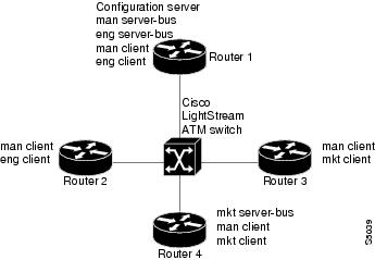
The following example configures four Cisco 7500 series routers for three emulated LANS for Engineering, Manufacturing, and Marketing, as shown in Figure 17. This example does not restrict membership in the emulated LANs.
Figure 17 Multiple Emulated LANs
In this example, Router 1 has the following LANE components:
•
•
•
•
•
Router 2 has the following LANE components:
•
•
Router 3 has the following LANE components:
•
•
Router 4 has the following LANE components:
•
•
•
For the purposes of this example, the four routers are assigned ATM address prefixes and end system identifiers (ESIs) as shown in Table 15 (the ESI part of the ATM address is derived from the first MAC address of the AIP shown in the example).
Router 1 Configuration
Router 1 has the LECS and its database, the server and BUS for the Manufacturing ELAN, the server and BUS for the Engineering ELAN, a client for Manufacturing, and a client for Engineering. Router 1 is configured as shown in this example:
!The following lines name and configure the configuration server's database.lane database example2name eng server-atm-address 39.000001415555121101020304.0800.200c.1001.02name eng local-seg-id 1000name man server-atm-address 39.000001415555121101020304.0800.200c.1001.01name man local-seg-id 2000name mkt server-atm-address 39.000001415555121101020304.0800.200c.4001.01name mkt local-seg-id 3000default-name man!! The following lines bring up the configuration server and associate! it with a database name.interface atm 1/0atm pvc 1 0 5 qsaalatm pvc 2 0 16 ilmilane config auto-config-atm-addresslane config database example2!! The following lines configure the "man" server, broadcast-and-unknown server,! and the client on atm subinterface 1/0.1. The client is assigned to the default! emulated lan.interface atm 1/0.1ip address 172.16.0.1 255.255.255.0lane server-bus tokenring manlane client tokenring man!! The following lines configure the "eng" server, broadcast-and-unknown server,! and the client on atm subinterface 1/0.2. The client is assigned to the! engineering emulated lan. Each emulated LAN is a different subnetwork, so the "eng"! client has an IP address on a different subnetwork than the "man" client.interface atm 1/0.2ip address 172.16.1.1 255.255.255.0lane server-bus tokenring englane client tokenring engRouter 2 Configuration
Router 2 is configured for a client of the Manufacturing ELAN and a client of the Engineering ELAN. Because the default ELAN name is man, the first client is linked to that ELAN name by default. Router 2 is configured as follows:
interface atm 1/0atm pvc 1 0 5 qsaalatm pvc 2 0 16 ilmiinterface atm 1/0.1ip address 172.16.0.2 255.255.255.0lane client tokenringinterface atm 1/0.2ip address 172.16.1.2 255.255.255.0lane client tokenring engRouter 3 Configuration
Router 3 is configured for a client of the Manufacturing ELAN and a client of the Marketing ELAN. Because the default ELAN name is man, the first client is linked to that ELAN name by default. Router 3 is configured as shown here:
interface atm 2/0atm pvc 1 0 5 qsaalatm pvc 2 0 16 ilmiinterface atm 2/0.1ip address 172.16.0.3 255.255.255.0lane client tokenringinterface atm 2/0.2ip address 172.16.2.3 255.255.255.0lane client tokenring mktRouter 4 Configuration
Router 4 has the server and BUS for the Marketing ELAN, a client for Marketing, and a client for Manufacturing. Because the default ELAN name is man, the second client is linked to that ELAN name by default. Router 4 is configured as shown here:
interface atm 3/0atm pvc 1 0 5 qsaalatm pvc 2 0 16 ilmiinterface atm 3/0.1ip address 172.16.2.4 255.255.255.0lane server-bus tokenring mktlane client tokenring mktinterface atm 3/0.2ip address 172.16.0.4 255.255.255.0lane client tokenringMultiple Token Ring ELANs with Restricted Membership Example
The following example, shown in Figure 18, configures a Cisco 7500 series router for three emulated LANS for Engineering, Manufacturing, and Marketing.
The same components are assigned to the four routers as in the previous example. The ATM address prefixes and MAC addresses are also the same as in the previous example.
However, this example restricts membership for the Engineering and Marketing emulated LANs. The LECS's database has explicit entries binding the ATM addresses of LANE clients to specified, named emulated LANs. In such cases, the client requests information from the LECS about which ELAN it should join; the LECS checks its database and replies to the client. Since the Manufacturing ELAN is unrestricted, any client not in the LECS's database is allowed to join it.
Figure 18 Multiple Emulated LANs with Restricted Membership
Router 1 Configuration
Router 1 has the LECS and its database, the server and BUS for the Manufacturing ELAN, the server and BUS for the Engineering ELAN, a client for Manufacturing, and a client for Engineering. It also has explicit database entries binding the ATM addresses of LANE clients to specified, named emulated LANs. Router 1 is configured as shown here:
! The following lines name and configure the configuration server's database.lane database example3name eng server-atm-address 39.000001415555121101020304.0800.200c.1001.02 restrictedname eng local-seg-id 1000name man server-atm-address 39.000001415555121101020304.0800.200c.1001.01name man local-seg-id 2000name mkt server-atm-address 39.000001415555121101020304.0800.200c.4001.01 restrictedname mkt local-seg-id 3000!! The following lines add database entries binding specified client ATM! addresses to emulated LANs. In each case, the Selector byte corresponds! to the subinterface number on the specified router.! The next command binds the client on Router 1's subinterface 2 to the eng ELAN.client-atm-address 39.0000014155551211.0800.200c.1000.02 name eng! The next command binds the client on Router 2's subinterface 2 to the eng ELAN.client-atm-address 39.0000014155551211.0800.200c.2000.02 name eng! The next command binds the client on Router 3's subinterface 2 to the mkt ELAN.client-atm-address 39.0000014155551211.0800.200c.3000.02 name mkt! The next command binds the client on Router 4's subinterface 1 to the mkt ELAN.client-atm-address 39.0000014155551211.0800.200c.4000.01 name mktdefault-name man!! The following lines bring up the configuration server and associate! it with a database name.interface atm 1/0atm pvc 1 0 5 qsaalatm pvc 2 0 16 ilmilane config auto-config-atm-addresslane config database example3!! The following lines configure the "man" server/broadcast-and-unknown server,! and the client on atm subinterface 1/0.1. The client is assigned to the default! emulated lan.interface atm 1/0.1ip address 172.16.0.1 255.255.255.0lane server-bus tokenring manlane client tokenring!! The following lines configure the "eng" server/broadcast-and-unknown server! and the client on atm subinterface 1/0.2. The configuration server assigns the! client to the engineering emulated lan.interface atm 1/0.2ip address 172.16.1.1 255.255.255.0lane server-bus tokenring englane client tokenring engRouter 2 Configuration
Router 2 is configured for a client of the Manufacturing ELAN and a client of the Engineering ELAN. Because the default ELAN name is man, the first client is linked to that ELAN name by default. Router 2 is configured as shown in this example:
interface atm 1/0atm pvc 1 0 5 qsaalatm pvc 2 0 16 ilmi! This client is not in the configuration server's database, so it will be! linked to the "man" ELAN by default.interface atm 1/0.1ip address 172.16.0.2 255.255.255.0lane client tokenring! A client for the following interface is entered in the configuration! server's database as linked to the "eng" ELAN.interface atm 1/0.2ip address 172.16.1.2 255.255.255.0lane client tokenring engRouter 3 Configuration
Router 3 is configured for a client of the Manufacturing ELAN and a client of the Marketing ELAN. Because the default ELAN name is man, the first client is linked to that ELAN name by default. The second client is listed in the database as linked to the mkt ELAN. Router 3 is configured as shown in this example:
interface atm 2/0atm pvc 1 0 5 qsaalatm pvc 2 0 16 ilmi! The first client is not entered in the database, so it is linked to the! "man" ELAN by default.interface atm 2/0.1ip address 172.16.0.3 255.255.255.0lane client tokenring man! The second client is explicitly entered in the configuration server's! database as linked to the "mkt" ELAN.interface atm 2/0.2ip address 172.16.2.3 255.255.255.0lane client tokenring mktRouter 4 Configuration
Router 4 has the server and BUS for the Marketing ELAN, a client for Marketing, and a client for Manufacturing. The first client is listed in the database as linked to the mkt emulated LANs. The second client is not listed in the database, but is linked to the man ELAN name by default. Router 4 is configured as shown here:
interface atm 3/0atm pvc 1 0 5 qsaalatm pvc 2 0 16 ilmi! The first client is explicitly entered in the configuration server's! database as linked to the "mkt" ELAN.interface atm 3/0.1ip address 172.16.2.4 255.255.255.0lane server-bus tokenring mktlane client tokenring mkt! The following client is not entered in the database, so it is linked to the! "man" ELAN by default.interface atm 3/0.2ip address 172.16.0.4 255.255.255.0lane client tokenringTR-LANE with 2-Port SRB Example
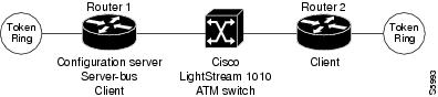
The following example configures two Cisco 7500 series routers for one emulated Token-Ring LAN using SRB, as shown in Figure 19. This example does not restrict membership in the emulated LANs.
Figure 19 2-Port SRB TR-LANE
Router 1 Configuration
Router 1 contains the LECS, the server and BUS, and a client. Router 1 is configured as shown in this example:
hostname Router1!! The following lines configure the database cisco_eng.lane database cisco_engname elan1 server-atm-address 39.020304050607080910111213.00000CA05B41.01name elan1 local-seg-id 2048default-name elan1!interface Ethernet0/0ip address 10.6.10.4 255.255.255.0!! The following lines configure a configuration server using the cisco_eng database on! the interface. No IP address is needed since we are using source-route bridging.interface ATM2/0no ip addressatm pvc 1 0 5 qsaalatm pvc 2 0 16 ilmilane config auto-config-atm-addresslane config database cisco_eng!! The following lines configure the server-bus and the client on the subinterface and! specify source-route bridging information.interface ATM2/0.1 multipointlane server-bus tokenring elan1lane client tokenring elan1source-bridge 2048 1 1source-bridge spanning!! The following lines configure source-route bridging on the Token Ring interface.interface TokenRing3/0/0no ip addressring-speed 16source-bridge 1 1 2048source-bridge spanning!router igrp 65529network 10.0.0.0Router 2 Configuration
Router 2 contains only a client for the ELAN. Router 2 is configured as shown here:
hostname Router2!interface Ethernet0/0ip address 10.6.10.5 255.255.255.0!! The following lines configure source-route bridging on the Token Ring interface.interface TokenRing1/0no ip addressring-speed 16source-bridge 2 2 2048source-bridge spanning!! The following lines set up the signalling and ILMI PVCs.interface ATM2/0no ip addressatm pvc 1 0 5 qsaalatm pvc 2 0 16 ilmi!! The following lines set up a client on the subinterface and configure! source-route bridging.interface ATM2/0.1 multipointip address 1.1.1.2 255.0.0.0lane client tokenring elan1source-bridge 2048 2 2source-bridge spanning!router igrp 65529network 10.0.0.0TR-LANE with Multiport SRB Example
The following example configures two Cisco 7500 series routers for one emulated Token-Ring LAN using SRB, as shown in Figure 20. Since each router connects to three rings (the two Token Rings and the ELAN "ring"), a virtual ring must be configured on the router. This example does not restrict membership in the emulated LANs.
Figure 20 Multiport SRB Token Ring ELAN
Router 1 Configuration
Router 1 contains the LECS, the server and BUS, and a client. Router 1 is configured as shown in this example:
hostname Router1!! The following lines configure the database with the information about the! elan1 emulated Token Ring LAN.lane database cisco_engname elan1 server-atm-address 39.020304050607080910111213.00000CA05B41.01name elan1 local-seg-id 2048default-name elan1!! The following line configures virtual ring 256 on the router.source-bridge ring-group 256!interface Ethernet0/0ip address 10.6.10.4 255.255.255.0!! The following lines configure the configuration server to use the cisco_eng database.! The Signalling and ILMI PVCs are also configured.interface ATM2/0no ip addressatm pvc 1 0 5 qsaalatm pvc 2 0 16 ilmilane config auto-config-atm-addresslane config database cisco_eng!! The following lines configure the server and broadcast-and-unknown server and a client! on the interface. The lines also specify source-route bridging information.interface ATM2/0.1 multipointlane server-bus tokenring elan1lane client tokenring elan1source-bridge 2048 5 256source-bridge spanning!! The following lines configure the Token Ring interfaces.interface TokenRing3/0no ip addressring-speed 16source-bridge 1 1 256source-bridge spanninginterface TokenRing3/1no ip addressring-speed 16source-bridge 2 2 256source-bridge spanning!router igrp 65529network 10.0.0.0Router 2 Configuration
Router 2 contains only a client for the ELAN. Router 2 is configured as follows:
hostname Router2!! The following line configures virtual ring 512 on the router.source-bridge ring-group 512!interface Ethernet0/0ip address 10.6.10.5 255.255.255.0!! The following lines configure the Token Ring interfaces.interface TokenRing1/0no ip addressring-speed 16source-bridge 3 3 512source-bridge spanninginterface TokenRing1/1no ip addressring-speed 16source-bridge 4 4 512source-bridge spanning!! The following lines configure the signalling and ILMI PVCs.interface ATM2/0no ip addressatm pvc 1 0 5 qsaalatm pvc 2 0 16 ilmi!! The following lines configure the client. Source-route bridging is also configured.interface ATM2/0.1 multipointip address 1.1.1.2 255.0.0.0lane client tokenring elan1source-bridge 2048 6 512source-bridge spanning!router igrp 65529network 10.0.0.0Routing Between Token Ring and Ethernet Emulated LANs Example
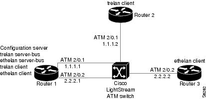
This example, shown in Figure 21, configures routing between a Token Ring ELAN (trelan) and an Ethernet ELAN (ethelan) on the same ATM interface. Router 1 contains the LECS, a LES and BUS for each ELAN, and a client for each ELAN. Router 2 contains a client for trelan (Token Ring); Router 3 contains a client for ethelan (Ethernet).
Figure 21 Routing Between Token Ring and Ethernet Emulated LANs
Router 1 Configuration
Router 1 contains the LECS, a LES and BUS for each ELAN, and a client for each ELAN. Router 1 is configured as shown in this example:
hostname router1!! The following lines name and configures the configuration server's database.! The server addresses for trelan and ethelan and the ELAN ring number for! trelan are entered into the database. The default ELAN is trelan.lane database cisco_engname trelan server-atm-address 39.020304050607080910111213.00000CA05B41.01name trelan local-seg-id 2048name ethelan server-atm-address 39.020304050607080910111213.00000CA05B41.02default-name trelan!! The following lines enable the configuration server and associate it! with the cisco_eng database.interface ATM2/0no ip addressatm pvc 1 0 5 qsaalatm pvc 2 0 16 ilmilane config auto-config-atm-addresslane config database cisco_eng!! The following lines configure the tokenring LES/BUS and LEC for trelan! on subinterface atm2/0.1 and assign an IP address to the subinterface.interface ATM2/0.1 multipointip address 10.1.1.1 255.255.255.0lane server-bus tokenring trelanlane client tokenring trelan!! The following lines configure the Ethernet LES/BUS and LEC for ethelan! on subinterface atm2/0.2 and assign an IP address to the subinterface.interface ATM2/0.2 multipointip address 20.2.2.1 255.255.255.0lane server-bus ethernet ethelanlane client ethernet ethelan!! The following lines configure the IGRP routing protocol to enable routing! between ELANS.router igrp 1network 10.0.0.0network 20.0.0.0Router 2 Configuration
Router 2 contains a client for trelan (Token Ring). Router 2 is configured as follows:
hostname router2!! The following lines set up the signalling and ILMI PVCs for the interface.interface ATM2/0no ip addressno keepaliveatm pvc 1 0 5 qsaalatm pvc 2 0 16 ilmi!! The following lines configure a Token Ring LEC on atm2/0.1 and assign! an IP address to the subinterface.interface ATM2/0.1 multipointip address 10.1.1.2 255.255.255.0lane client tokenring trelan!! The following lines configure the IGRP routing protocol to enable routing! between ELANS.router igrp 1network 10.0.0.0network 20.0.0.0Router 3 Configuration
Router 3 contains a client for ethelan (Ethernet). Router 3 is configured as follows:
hostname router3!! The following lines set up the signalling and ILMI PVCs for the interface.interface ATM2/0no ip addressno ip mroute-cacheatm pvc 1 0 5 qsaalatm pvc 2 0 16 ilmi!! The following lines configure an Ethernet LEC on atm2/0.1 and assign! an IP address to the subinterface.interface ATM2/0.1 multipointip address 20.2.2.2 255.255.255.0lane client ethernet ethelan!! The following lines configure the IGRP routing protocol to enable routing! between ELANS.router igrp 1network 10.0.0.0network 20.0.0.0Disabling LANE Flush Process Example
The following example shows a running configuration and the LE_FLUSH process disabled for all LECs:
more system:running-configBuilding configuration...Current configuration :496 bytes!! Last configuration change at 11:36:21 UTC Thu Dec 20 2001!version 12.1service timestamps debug uptimeservice timestamps log uptimeno service password-encryption!hostname donner_b!no lane client flush!interface ATM0atm preferred phy Aatm pvc 1 0 5 qsaalatm pvc 2 0 16 ilmino atm ilmi-keepalive!interface ATM0.1 multipointlane config-atm-address 47.009181000000001007385101.0050A2FEBC43.00lane client ethernet 100 elan1!line con 0line vty 0 4no login!end
Any Internet Protocol (IP) addresses used in this document are not intended to be actual addresses. Any examples, command display output, and figures included in the document are shown for illustrative purposes only. Any use of actual IP addresses in illustrative content is unintentional and coincidental.
© 2007 Cisco Systems, Inc. All rights reserved.