Feedback
Table Of Contents
Prerequisites for L2VPN Pseudowire Redundancy
Restrictions for L2VPN Pseudowire Redundancy
Information About L2VPN Pseudowire Redundancy
Introduction to L2VPN Pseudowire Redundancy
How to Configure L2VPN Pseudowire Redundancy
Configuring L2VPN Pseudowire Redundancy
Forcing a Manual Switchover to the Backup Pseudowire VC
Verifying the L2VPN Pseudowire Redundancy Configuration
Configuration Examples for L2VPN Pseudowire Redundancy
L2VPN Pseudowire Redundancy and AToM (Like to Like): Examples
L2VPN Pseudowire Redundancy and L2VPN Interworking: Examples
L2VPN Pseudowire Redundancy with Layer 2 Local Switching: Examples
backup delay (L2VPN local switching)
xconnect backup force-switchover
Feature Information for L2VPN Pseudowire Redundancy
L2VPN Pseudowire Redundancy
First Published: April 20, 2005Last Updated: February 19, 2007The L2VPN Pseudowire Redundancy feature enables you to configure your network to detect a failure in the network and reroute the Layer 2 (L2) service to another endpoint that can continue to provide service. This feature provides the ability to recover from a failure either of the remote provider edge (PE) router or of the link between the PE and customer edge (CE) routers.
Finding Feature Information in This Module
Your Cisco IOS software release may not support all of the features documented in this module. To reach links to specific feature documentation in this module and to see a list of the releases in which each feature is supported, use the "Feature Information for L2VPN Pseudowire Redundancy" section.
Finding Support Information for Platforms and Cisco IOS and Catalyst OS Software Images
Use Cisco Feature Navigator to find information about platform support and Cisco IOS and Catalyst OS software image support. To access Cisco Feature Navigator, go to http://www.cisco.com/go/cfn. An account on Cisco.com is not required.
Contents
•
Prerequisites for L2VPN Pseudowire Redundancy
•
•
•
•
•
Prerequisites for L2VPN Pseudowire Redundancy
•
–
–
•
–
–
–
Restrictions for L2VPN Pseudowire Redundancy
•
•
•
•
•
•
•
•
•
•
•
Information About L2VPN Pseudowire Redundancy
Before configuring L2VPN Pseudowire Redundancy, you should understand the following concept:
•
Introduction to L2VPN Pseudowire Redundancy
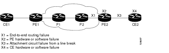
L2VPNs can provide pseudowire resiliency through their routing protocols. When connectivity between end-to-end PE routers fails, an alternative path to the directed LDP session and the user data can take over. However, there are some parts of the network where this rerouting mechanism does not protect against interruptions in service. Figure 1 shows those parts of the network that are vulnerable to an interruption in service.
Figure 1 Points of Potential Failure in an L2VPN Network
The L2VPN Pseudowire Redundancy feature provides the ability to ensure that the CE2 router in Figure 1 can always maintain network connectivity, even if one or all the failures in the figure occur.
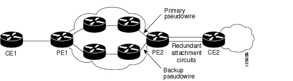
The L2VPN Pseudowire Redundancy feature enables you to set up backup pseudowires. You can configure the network with redundant pseudowires (PWs) and redundant network elements, which are shown in the following figures.
Figure 2 shows a network with redundant pseudowires and redundant attachment circuits.
Figure 2 L2 VPN Network with Redundant PWs and Attachment Circuits
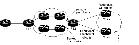
Figure 3 shows a network with redundant pseudowires, attachment circuits, and CE routers.
Figure 3 L2 VPN Network with Redundant PWs, Attachment Circuits, and CE Routers
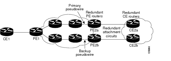
Figure 4 shows a network with redundant pseudowires, attachment circuits, CE routers, and PE routers.
Figure 4 L2 VPN Network with Redundant PWs, Attachment Circuits, CE Routers,
and PE Routers
How to Configure L2VPN Pseudowire Redundancy
The L2VPN Pseudowire Redundancy feature enables you to configure a backup pseudowire in case the primary pseudowire fails. When the primary pseudowire fails, the PE router can switch to the backup pseudowire. You can have the primary pseudowire resume operation after it comes back up.
The following sections explain how to configure the L2VPN Pseudowire Redundancy feature:
•
•
•
•
Configuring the Pseudowire
The successful transmission of the Layer 2 frames between PE routers is due to the configuration of the PE routers. You set up the connection, called a pseudowire, between the routers.
The pseudowire-class configuration group specifies the characteristics of the tunneling mechanism, which are:
•
•
•
You must specify the encapsulation mpls command as part of the pseudowire class for the AToM VCs to work properly. If you omit the encapsulation mpls command as part of the xconnect command, you receive the following error:
% Incomplete command.Perform this task to configure a pseudowire class.
SUMMARY STEPS
1.
2.
3.
4.
5.
DETAILED STEPS
Configuring L2VPN Pseudowire Redundancy
Use the following steps to configure the L2VPN Pseudowire Redundancy feature.
Prerequisites
For each transport type, the xconnect command is configured slightly differently. The following configuration steps use Ethernet VLAN over MPLS, which is configured in subinterface configuration mode. See Any Transport over MPLS to determine how to configure the xconnect command for other transport types.
SUMMARY STEPS
1.
2.
3.
4.
5.
6.
7.
DETAILED STEPS
Forcing a Manual Switchover to the Backup Pseudowire VC
To force the router switch over to the backup or primary pseudowire, you can enter the xconnect backup force switchover command in privileged EXEC mode. You can specify either the interface of the primary attachment circuit (AC) to switch to or the IP-address and VC ID of the peer router.
A manual switchover can be made only if the interface or peer specified in the command is actually available and the xconnect will move to the fully active state when the command is entered.
SUMMARY STEPS
1.
2.
DETAILED STEPS
Verifying the L2VPN Pseudowire Redundancy Configuration
Use the following commands to verify that the L2VPN Pseudowire Redundancy feature is correctly configured.
SUMMARY STEPS
1.
2.
3.
DETAILED STEPS
Step 1
In this example, the primary attachment circuit is up. The backup attachment circuit is available, but not currently selected. The show output displays as follows:
Router# show mpls l2transport vcLocal intf Local circuit Dest address VC ID Status------------- ----------------------- --------------- ---------- ----------Et0/0.1 Eth VLAN 101 10.0.0.2 101 UPEt0/0.1 Eth VLAN 101 10.0.0.3 201 DOWNRouter# show mpls l2transport vc detailLocal interface: Et0/0.1 up, line protocol up, Eth VLAN 101 upDestination address 10.0.0.2 VC ID: 101, VC status UP...Local interface: Et0/0.1 down, line protocol down, Eth VLAN 101 downDestination address 10.0.0.3 VC ID: 201, VC status down...Step 2
In this example, the topology is Attachment Circuit 1 to Pseudowire 1 with a Pseudowire 2 as a backup:
Router# show xconnect allLegend: XC ST=Xconnect State, S1=Segment1 State, S2=Segment2 StateUP=Up, DN=Down, AD=Admin Down, IA=Inactive, NH=No HardwareXC ST Segment 1 S1 Segment 2 S2------+---------------------------------+--+---------------------------------+--UP pri ac Et0/0(Ethernet) UP mpls 10.55.55.2:1000 UPIA sec ac Et0/0(Ethernet) UP mpls 10.55.55.3:1001 DNIn this example, the topology is Attachment Circuit 1 to Attachment Circuit 2 with a Pseudowire backup for Attachment Circuit 2:
Router# show xconnect allLegend: XC ST=Xconnect State, S1=Segment1 State, S2=Segment2 StateUP=Up, DN=Down, AD=Admin Down, IA=Inactive, NH=No HardwareXC ST Segment 1 S1 Segment 2 S2------+---------------------------------+--+---------------------------------+--UP pri ac Se6/0:150(FR DLCI) UP ac Se8/0:150(FR DLCI) UPIA sec ac Se6/0:150(FR DLCI) UP mpls 10.55.55.3:7151 DNStep 3
In addition to the show mpls l2transport vc command and the show xconnect command, you can use the xconnect logging redundancy command to track the status of the xconnect redundancy group:
Router(config)# xconnect logging redundancyWhen this command is configured, the following messages will be generated during switchover events:
Activating the primary member:
00:01:07: %XCONNECT-5-REDUNDANCY: Activating primary member 10.55.55.2:1000Activating the backup member:
00:01:05: %XCONNECT-5-REDUNDANCY: Activating secondary member 10.55.55.3:1001Configuration Examples for L2VPN Pseudowire Redundancy
The following sections show the L2VPN Pseudowire Redundancy feature examples. These configuration examples show how the L2VPN Pseudowire Redundancy feature can be configured with the AToM (like-to-like), L2VPN Interworking, and Layer 2 Local Switching features.
•
•
•
Each of the configuration examples refers to one of the following pseudowire classes:
•
pseudowire-class mplsencapsulation mpls•
pseudowire-class mpls-ipencapsulation mplsinterworking ipL2VPN Pseudowire Redundancy and AToM (Like to Like): Examples
The following example shows a High-Level Data Link Control (HDLC) attachment circuit xconnect with a backup pseudowire:
interface Serial4/0xconnect 10.55.55.2 4000 pw-class mplsbackup peer 10.55.55.3 4001 pw-class mplsThe following example shows a Frame Relay attachment circuit xconnect with a backup pseudowire:
connect fr-fr-pw Serial6/0 225 l2transportxconnect 10.55.55.2 5225 pw-class mplsbackup peer 10.55.55.3 5226 pw-class mplsL2VPN Pseudowire Redundancy and L2VPN Interworking: Examples
The following example shows an Ethernet attachment circuit xconnect with L2VPN IP interworking and a backup pseudowire:
interface Ethernet0/0xconnect 10.55.55.2 1000 pw-class mpls-ipbackup peer 10.55.55.3 1001 pw-class mpls-ipThe following example shows an Ethernet VLAN attachment circuit xconnect with L2VPN IP interworking and a backup pseudowire:
interface Ethernet1/0.1encapsulation dot1Q 200no ip directed-broadcastxconnect 10.55.55.2 5200 pw-class mpls-ipbackup peer 10.55.55.3 5201 pw-class mpls-ipThe following example shows a Frame Relay attachment circuit xconnect with L2VPN IP interworking and a backup pseudowire:
connect fr-ppp-pw Serial6/0 250 l2transportxconnect 10.55.55.2 8250 pw-class mpls-ipbackup peer 10.55.55.3 8251 pw-class mpls-ipThe following example shows a PPP attachment circuit xconnect with L2VPN IP interworking and a backup pseudowire:
interface Serial7/0encapsulation pppxconnect 10.55.55.2 2175 pw-class mpls-ipbackup peer 10.55.55.3 2176 pw-class mpls-ipL2VPN Pseudowire Redundancy with Layer 2 Local Switching: Examples
The following example shows an Ethernet VLAN-VLAN local switching xconnect with a pseudowire backup for Ethernet segment E2/0.2. If the subinterface associated with E2/0.2 goes down, the backup pseudowire is activated.
connect vlan-vlan Ethernet1/0.2 Ethernet2/0.2backup peer 10.55.55.3 1101 pw-class mplsThe following example shows a Frame Relay-to-Frame Relay local switching connect with a pseudowire backup for Frame Relay segment S8/0 150. If data-link connection identifier (DLCI) 150 on S8/0 goes down, the backup pseudowire is activated.
connect fr-fr-ls Serial6/0 150 Serial8/0 150backup peer 10.55.55.3 7151 pw-class mplsAdditional References
The following sections provide references related to the L2VPN Pseudowire Redundancy feature.
Related Documents
Any Transport over MPLS
High Availability for AToM
L2VPN Interworking
Layer 2 Local Switching
PWE3 MIB
Pseudowire Emulation Edge-to-Edge MIBs for Ethernet and Frame Relay Services
Packet Sequencing
Standards
MIBs
None
To locate and download MIBs for selected platforms, Cisco IOS releases, and feature sets, use Cisco MIB Locator found at the following URL:
RFCs
Technical Assistance
Command Reference
This section documents modified commands only.
•
•
backup delay (L2VPN local switching)
To specify how long a backup pseudowire virtual circuit (VC) should wait before resuming operation after the primary pseudowire VC goes down, use the backup delay command in interface configuration mode or xconnect configuration mode.
backup delay enable-delay {disable-delay | never}
Syntax Description
Command Default
If a failover occurs, the xconnect redundancy algorithm will immediately switch over or fall back to the backup or primary member in the redundancy group.
Command Modes
Interface configuration
Xconnect configurationCommand History
Examples
The following example shows a Multiprotocol Label Switching (MPLS) xconnect with one redundant peer. Once a switchover to the secondary VC occurs, there will be no fallback to the primary VC unless the secondary VC fails.
Router(config)# pseudowire-class mplsRouter(config-pw-class)# encapsulation mplsRouter(config)# connect frpw1 serial0/1 50 l2transportRouter(config-if)# xconnect 10.0.0.1 50 pw-class mplsRouter(config-if-xconn)# backup peer 10.0.0.2 50Router(config-if-xconn)# backup delay 0 neverThe following example shows an MPLS xconnect with one redundant peer. The switchover will not begin unless the Layer 2 Tunnel Protocol (L2TP) pseudowire has been down for 3 seconds. After a switchover to the secondary VC occurs, there will be no fallback to the primary until the primary VC has been reestablished and is up for 10 seconds.
Router(config)# pseudowire-class mplsRouter(config-pw-class)# encapsulation mplsRouter(config)# connect frpw1 serial0/1 50 l2transportRouter(config-if)# xconnect 10.0.0.1 50 pw-class mplsRouter(config-if-xconn)# backup peer 10.0.0.2 50Router(config-if-xconn)# backup delay 3 10Related Commands
backup peer
To specify a redundant peer for a pseudowire virtual circuit (VC), use the backup peer command in interface configuration mode or xconnect configuration mode. To remove the redundant peer, use the no form of this command.
backup peer peer-router-ip-addr vcid [pw-class pw-class-name]
no backup peer peer-router-ip-addr vcid
Syntax Description
Command Default
No redundant peer is established.
Command Modes
Interface configuration
Xconnect configurationCommand History
Usage Guidelines
The combination of the peer-router-ip-addr and vcid arguments must be unique on the router.
Examples
The following example shows a Multiprotocol Label Switching (MPLS) xconnect with one redundant peer:
Router(config)# pseudowire-class mplsRouter(config-pw-class)# encapsulation mplsRouter(config)# interface serial0/0Router(config-if)# xconnect 10.0.0.1 100 pw-class mplsRouter(config-if-xconn)# backup peer 10.0.0.2 200The following example shows a local-switched connection between ATM and Frame Relay using Ethernet interworking. The Frame Relay circuit is backed up by an MPLS pseudowire.
Router(config)# pseudowire-class mplsRouter(config-pw-class)# encapsulation mplsRouter(config-pw-class)# interworking ethernetRouter(config)# connect atm-fr atm1/0 100/100 s2/0 100 interworking ethernetRouter(config-if)# backup peer 10.0.0.2 100 pw-class mplsRelated Commands
backup delay
Specifies how long the backup pseudowire VC should wait before resuming operation after the primary pseudowire VC goes down.
show xconnect
To display information about xconnect attachment circuits and pseudowires, use the show xconnect command in privileged EXEC mode.
show xconnect {all | interface interface | peer ip-address {all | vcid vcid}} [detail]
Syntax Description
Command Modes
Privileged EXEC
Command History
Usage Guidelines
The show xconnect command can be used to display, sort, and filter basic information about all xconnect attachment circuits and pseudowires.
You can use the show xconnect command output to help determine the appropriate steps to take to troubleshoot an xconnect configuration problem. More specific information about a particular type of xconnect can be displayed using the commands listed in the "Related Commands" table.
Examples
The following example shows show xconnect all command output in the brief (default) display format:
Router# show xconnect allLegend: XC ST=Xconnect State, S1=Segment1 State, S2=Segment2 StateUP=Up, DN=Down, AD=Admin Down, IA=Inactive, NH=No HardwareXC ST Segment 1 S1 Segment 2 S2------+---------------------------------+--+---------------------------------+--UP ac Et0/0(Ethernet) UP mpls 10.55.55.2:1000 UPUP ac Se7/0(PPP) UP mpls 10.55.55.2:2175 UPUP pri ac Se6/0:230(FR DLCI) UP mpls 10.55.55.2:2230 UPIA sec ac Se6/0:230(FR DLCI) UP mpls 10.55.55.3:2231 DNUP ac Se4/0(HDLC) UP mpls 10.55.55.2:4000 UPUP ac Se6/0:500(FR DLCI) UP l2tp 10.55.55.2:5000 UPUP ac Et1/0.1:200(Eth VLAN) UP mpls 10.55.55.2:5200 UPUP pri ac Se6/0:225(FR DLCI) UP mpls 10.55.55.2:5225 UPIA sec ac Se6/0:225(FR DLCI) UP mpls 10.55.55.3:5226 DNIA pri ac Et1/0.2:100(Eth VLAN) UP ac Et2/0.2:100(Eth VLAN) UPUP sec ac Et1/0.2:100(Eth VLAN) UP mpls 10.55.55.3:1101 UPUP ac Se6/0:150(FR DLCI) UP ac Se8/0:150(FR DLCI) UPTable 1 describes the significant fields shown in the display.
The following example shows show xconnect all command output in the detailed display format:
Router# show xconnect all detailLegend: XC ST=Xconnect State, S1=Segment1 State, S2=Segment2 StateUP=Up, DN=Down, AD=Admin Down, IA=Inactive, NH=No HardwareXCST Segment 1 S1 Segment 2 S2------+---------------------------------+--+---------------------------------+--UP ac Et0/0(Ethernet) UP mpls 10.55.55.2:1000 UPInterworking: ip Local VC label 16Remote VC label 16pw-class: mpls-ipUP ac Se7/0(PPP) UP mpls 10.55.55.2:2175 UPInterworking: ip Local VC label 22Remote VC label 17pw-class: mpls-ipUP pri ac Se6/0:230(FR DLCI) UP mpls 10.55.55.2:2230 UPInterworking: ip Local VC label 21Remote VC label 18pw-class: mpls-ipIA sec ac Se6/0:230(FR DLCI) UP mpls 10.55.55.3:2231 DNInterworking: ip Local VC label unassignedRemote VC label 19pw-class: mpls-ipUP ac Se4/0(HDLC) UP mpls 10.55.55.2:4000 UPInterworking: none Local VC label 18Remote VC label 19pw-class: mplsUP ac Se6/0:500(FR DLCI) UP l2tp 10.55.55.2:5000 UPInterworking: none Session ID: 34183Tunnel ID: 62083Peer name: pe-iou2Protocol State: UPRemote Circuit State: UPpw-class: l2tpUP ac Et1/0.1:200(Eth VLAN) UP mpls 10.55.55.2:5200 UPInterworking: ip Local VC label 17Remote VC label 20pw-class: mpls-ipUP pri ac Se6/0:225(FR DLCI) UP mpls 10.55.55.2:5225 UPInterworking: none Local VC label 19Remote VC label 21pw-class: mplsIA sec ac Se6/0:225(FR DLCI) UP mpls 10.55.55.3:5226 DNInterworking: none Local VC label unassignedRemote VC label 22pw-class: mplsIA pri ac Et1/0.2:100(Eth VLAN) UP ac Et2/0.2:100(Eth VLAN) UPInterworking: none Interworking: noneUP sec ac Et1/0.2:100(Eth VLAN) UP mpls 10.55.55.3:1101 UPInterworking: none Local VC label 23Remote VC label 17pw-class: mplsUP ac Se6/0:150(FR DLCI) UP ac Se8/0:150(FR DLCI) UPInterworking: none Interworking: noneThe additional fields displayed in the detailed output are self-explanatory.
Related Commands
xconnect backup force-switchover
To manually force a switchover to an attachment circuit or a pseudowire peer, use the xconnect backup force-switchover command in privileged EXEC mode.
xconnect backup force-switchover interface {interface-info | peer ip-address vcid}
Syntax Description
interface
interface-Specifies the interface to be used for the switchover.
peer
ip-address vcidSpecifies the IP address and virtual circuit (VC) ID of the VC to be used for the switchover.
Command Default
The pseudowire VC will not be changed.
Command Modes
Privileged EXEC
Command History
Usage Guidelines
You can perform a switchover only to an available member in the redundancy group. That is, if the member being specified in the xconnect backup force-switchover command is not available, the command will be rejected.
Examples
The following example shows a Multiprotocol Label Switching (MPLS) xconnect with two redundant peers. The primary xconnect is using IP address 10.55.55.1, VC ID 500.
Router(config)# interface fastethernet1/0Router(config-if)# xconnect 10.55.55.1 500 encapsulation mplsRouter(config-if-xconn)# backup peer 10.55.55.2 501!Router# xconnect backup force-switchover peer 10.55.55.2 501Entering the xconnect backup force-switchover command will cause the router to switch to the pseudowire with an IP address of 10.55.55.2, VC ID 501.
To switch back to the primary pseudowire, enter the following command:
Router# xconnect backup force-switchover peer 10.55.55.1 500If the xconnect cannot be switched over to the redundant pseudowire specified by the user, the standard redundancy algorithm will run and select either the primary or the highest secondary VC, depending on current availability.
The following example shows a local switching connection with two redundant peers. The primary xconnect is VLAN subinterface FastEthernet0/1.1 using dot1q tag 10. The xconnect is currently established with one of the backup peers when the manual switchover is issued to the primary xconnect.
Router(config)# interface FastEthernet0/0!Router(config)# interface FastEthernet0/1.1Router(config-if)# encapsulation dot1Q 10!Router(config)# connect eth-vln FastEthernet0/0 FastEthernet0/1.1 interworking ethernetRouter(config-if)# backup peer 10.55.55.2 501!Router# xconnect backup force-switchover interface FastEthernet0/1.1Entering the xconnect backup force-switchover command will cause the router to switch back to the VLAN subinterface FastEthernet0/1.1. If the xconnect cannot be switched over to the primary VLAN subinterface specified by the user, the standard redundancy algorithm will run and select the highest secondary VC, depending on current availability.
Related Commands
xconnect logging redundancy
To enable system message log (syslog) reporting of the status of the xconnect redundancy group, use the xconnect logging redundancy command in global configuration mode. To disable syslog reporting of the status of the xconnect redundancy group, use the no form of this command.
xconnect logging redundancy
no xconnect logging redundancy
Syntax Description
This command has no arguments or keywords.
Command Default
Syslog reporting of the status of the xconnect redundancy group is disabled.
Command Modes
Global configuration
Command History
Usage Guidelines
Use this command to enable syslog reporting of the status of the xconnect redundancy group.
Examples
The following example enables syslog reporting of the status of the xconnect redundancy group and shows the messages that are generated during switchover events:
Router(config)# xconnect logging redundancyActivating the primary member:
00:01:07: %XCONNECT-5-REDUNDANCY: Activating primary member 10.55.55.2:1000Activating the backup member:
00:01:05: %XCONNECT-5-REDUNDANCY: Activating secondary member 10.55.55.3:1001Related Commands
xconnect
Binds an Ethernet, 802.1q VLAN, or Frame Relay attachment circuit to an L2TPv3 pseudowire for xconnect service and enters xconnect configuration mode.
Feature Information for L2VPN Pseudowire Redundancy
Table 2 lists the release history for this feature.
Not all commands may be available in your Cisco IOS software release. For release information about a specific command, see the command reference documentation.
Use Cisco Feature Navigator to find information about platform support and software image support. Cisco Feature Navigator enables you to determine which Cisco IOS and Catalyst OS software images support a specific software release, feature set, or platform. To access Cisco Feature Navigator, go to http://www.cisco.com/go/cfn. An account on Cisco.com is not required.
Note
Table 2 Feature Information for L2VPN Pseudowire Redundancy
L2VPN Pseudowire Redundancy
12.0(31)S
12.2(28)SB
12.4(11)T
12.2(33)SRBThis feature enables you to set up your network to detect a failure in the network and reroute the Layer 2 service to another endpoint that can continue to provide service.
In 12.0(31)S, the L2VPN Pseudowire Redundancy feature was introduced for Any Transport over MPLS (AToM) on the Cisco 12000 series routers.
This feature was integrated into Cisco IOS Release 12.2(28)SB.
This feature was integrated into Cisco IOS Release 12.4(11)T.
Use Cisco Feature Navigator to find information about platform support and Cisco IOS software image support.
CCVP, the Cisco Logo, and the Cisco Square Bridge logo are trademarks of Cisco Systems, Inc.; Changing the Way We Work, Live, Play, and Learn is a service mark of Cisco Systems, Inc.; and Access Registrar, Aironet, BPX, Catalyst, CCDA, CCDP, CCIE, CCIP, CCNA, CCNP, CCSP, Cisco, the Cisco Certified Internetwork Expert logo, Cisco IOS, Cisco Press, Cisco Systems, Cisco Systems Capital, the Cisco Systems logo, Cisco Unity, Enterprise/Solver, EtherChannel, EtherFast, EtherSwitch, Fast Step, Follow Me Browsing, FormShare, GigaDrive, GigaStack, HomeLink, Internet Quotient, IOS, iPhone, IP/TV, iQ Expertise, the iQ logo, iQ Net Readiness Scorecard, iQuick Study, LightStream, Linksys, MeetingPlace, MGX, Networking Academy, Network Registrar, Packet, PIX, ProConnect, RateMUX, ScriptShare, SlideCast, SMARTnet, StackWise, The Fastest Way to Increase Your Internet Quotient, and TransPath are registered trademarks of Cisco Systems, Inc. and/or its affiliates in the United States and certain other countries.
All other trademarks mentioned in this document or Website are the property of their respective owners. The use of the word partner does not imply a partnership relationship between Cisco and any other company. (0612R)
Any Internet Protocol (IP) addresses used in this document are not intended to be actual addresses. Any examples, command display output, and figures included in the document are shown for illustrative purposes only. Any use of actual IP addresses in illustrative content is unintentional and coincidental.
© 2005-2007 Cisco Systems, Inc. All rights reserved.