Table Of Contents
L2VPN Interworking
Contents
Prerequisites for L2VPN Interworking
Restrictions for L2VPN Interworking
General Restrictions
Cisco 7200 and 7500 Series Routers Supported Port Adapters
Cisco 7200 Series Routers Supported Interface Processors
Cisco 7500 Series Routers Supported Interface Processors
Cisco 10720 Internet Router Supported Line Cards
Cisco 12000 Series Router Restrictions
Cisco 12000 Series Routers Supported Line Cards
Cisco 7600 Series Router Supported Line Cards
Cisco 7600 Series Routers Restrictions
Unsupported Hardware
ATM AAL5 Interworking Restrictions
Ethernet/VLAN Interworking Restrictions
Frame Relay Interworking Restrictions
PPP Interworking Restrictions
Information About L2VPN Interworking
Overview of L2VPN Interworking
L2VPN Interworking Modes
Ethernet Interworking
IP Interworking
How to Configure L2VPN Interworking
Configuring L2VPN Interworking
Configuring Static IP Addresses for L2VPN Interworking for PPP
Verifying the L2VPN Interworking Configuration
Configuration Examples for L2VPN Interworking
Ethernet to VLAN over L2TPV3 (Bridged): Example
Ethernet to VLAN over AToM (Bridged): Example
Frame Relay to VLAN over L2TPV3 (Routed): Example
Frame Relay to VLAN over AToM (Routed): Example
Frame Relay to ATM AAL5 over AToM (Routed): Example
VLAN to ATM AAL5 over AToM (Bridged): Example
Frame Relay to PPP over L2TPv3 (Routed): Example
Frame Relay to PPP over AToM (Routed): Example
Ethernet/VLAN to PPP over AToM (Routed): Example
Additional References
Related Documents
Standards
MIBs
RFCs
Technical Assistance
Command Reference
debug frame-relay pseudowire
debug ssm
interworking
mtu
show l2tun session
show l2tun tunnel
show mpls l2transport vc
Feature Information for L2VPN Interworking
L2VPN Interworking
First Published: August 26, 2003
Last Updated: February 15, 2007
This feature module explains how to configure the following Layer 2 Virtual Private Network (L2VPN) Interworking features:
•
Ethernet/VLAN to ATM AAL5 Interworking
•
Ethernet/VLAN to Frame Relay Interworking
•
Ethernet/VLAN to PPP Interworking
•
Ethernet to VLAN Interworking
•
Frame Relay to ATM AAL5 Interworking
•
Frame Relay to PPP Interworking
Finding Feature Information in This Module
Your Cisco IOS software release may not support all of the features documented in this module. To reach links to specific feature documentation in this module and to see a list of the releases in which each feature is supported, use the "Feature Information for L2VPN Interworking" section.
Finding Support Information for Platforms and Cisco IOS Software Images
Use Cisco Feature Navigator to find information about platform support and Cisco IOS software image support. Access Cisco Feature Navigator at http://www.cisco.com/go/fn. You must have an account on Cisco.com. If you do not have an account or have forgotten your username or password, click Cancel at the login dialog box and follow the instructions that appear.
Contents
•
Prerequisites for L2VPN Interworking
•
Restrictions for L2VPN Interworking
•
Information About L2VPN Interworking
•
How to Configure L2VPN Interworking
•
Configuration Examples for L2VPN Interworking
•
Additional References
•
Command Reference
•
Feature Information for L2VPN Interworking
Prerequisites for L2VPN Interworking
Before you configure L2VPN Interworking on a router:
•
You must enable Cisco Express Forwarding .
•
On the Cisco 12000 series Internet router, before you configure Layer 2 Tunnel Protocol version 3 (L2TPv3) for L2VPN Interworking on an IP Services Engine (ISE/Engine 3) or Engine 5 interface, you must also enable the L2VPN feature bundle on the line card. To enable the feature bundle, enter the hw-module slot np mode feature command in global configuration mode as follows:
Router# configure terminal
Router(config)# hw-module slot slot-number np mode feature
Restrictions for L2VPN Interworking
The following sections list the L2VPN Interworking restrictions:
•
General Restrictions
•
Cisco 7200 and 7500 Series Routers Supported Port Adapters
•
Cisco 7200 Series Routers Supported Interface Processors
•
Cisco 7500 Series Routers Supported Interface Processors
•
Cisco 10720 Internet Router Supported Line Cards
•
Cisco 12000 Series Router Restrictions
•
Cisco 12000 Series Routers Supported Line Cards
•
Cisco 7600 Series Router Supported Line Cards
•
Cisco 7600 Series Router Supported Line Cards
•
Cisco 7600 Series Routers Restrictions
•
Unsupported Hardware
•
ATM AAL5 Interworking Restrictions
•
Ethernet/VLAN Interworking Restrictions
•
Frame Relay Interworking Restrictions
•
PPP Interworking Restrictions
General Restrictions
This section lists general restrictions that apply to L2VPN Interworking. Other restrictions that are platform- or device-specific are listed in the following sections.
•
The interworking type on one provider edge (PE) router must match the interworking type on the peer PE router.
•
Distributed Cisco Express Forwarding switching is supported on the Cisco 7500.
•
Although Layer 2 quality of service (QoS) is supported extensively on Cisco 12000 series routers (details are given in Any Transport over MPLS (AToM): Layer 2 QoS (Quality of Service) for the Cisco 12000 Series Router), on other platforms only the following QoS features are supported with L2VPN Interworking:
–
Static IP type of service (ToS) or Multiprotocol Label Switching (MPLS) experimental bit (EXP) setting in tunnel header
–
IP ToS reflection in tunnel header (Layer 2 Tunnel Protocol Version 3 (L2TPv3) only)
–
Frame Relay policing
–
Frame Relay data-link connection identifier (DLCI)-based congestion management (Cisco 7500/Versatile Interface Processor (VIP))
–
One-to-one mapping of VLAN priority bits to MPLS EXP bits
Cisco 7200 and 7500 Series Routers Supported Port Adapters
L2VPN Interworking is supported only on the following port adapters in the Cisco 7200 and 7500 series routers:
•
PA-FE-TX (single-port Fast Ethernet 100BASE-TX)
•
PA-FE-FX (single-port Fast Ethernet 100BASE-FX)
•
PA-2FE-TX (dual-port Fast Ethernet 100BASE-TX)
•
PA-2FE-FX (dual-port Fast Ethernet 100BASE-FX)
•
PA-8E (8-port Ethernet Adapter) [7200 only, L2TPv3 only]
•
PA-4E (4-port Ethernet Adapter) [7200 only, L2TPv3 only]
•
PA-12E/2FE (12-port Ethernet/2-port FE Adapter) [7200 only, L2TPv3 only]
•
PA-GE (Gigabit Ethernet Port Adapter) [7200 only]
•
PA-4T (4-port synchronous serial port adapter)
•
PA-4T+ (enhanced 4-port synchronous serial port adapter)
•
PA-8T (8-port synchronous serial port adapter)
•
PA-H—single-port High-Speed Serial Interface (HSSI) adapter
•
PA-2H (dual-port HSSI adapter)
•
PA-MC-8E1 (8-port multichannel E1 G.703/G.704 120-ohm interfaces)
•
PA-MC-2EI (2-port multichannel E1 G.703/G.704 120-ohm interfaces)
•
PA-MC-8T1—8-port multichannel T1 with integrated channel service unit (CSU) and data service unit (DSUs)
•
PA-MC-4T1 (4-port multichannel T1 with integrated CSUs and DSUs)
•
PA-MC-2T1 (2-port multichannel T1 with integrated CSUs and DSUs)
•
PA-MC-8TE1+ (8-port multichannel T1/E1)
•
PA-MC-T3 (1-port multichannel T3 interface)
•
PA-MC-E3 (1-port multichannel E3 interface)
•
PA-MC-2T3+ (2-port enhanced multichannel T3 port adapter)
•
PA-MC-STM1 (1-port multichannel STM-1 port adapter)
•
PA-T3 (single-port T3 port adapter)
•
PA-E3 (single-port E3 port adapter)
•
PA-2E3 (2-port T3 port adapter)
•
PA-2T3 (2-port T3 port adapter)
•
PA-POS-OC3SML- (single-port Packet over SONET (POS), Single-mode, long reach)
•
PA-POS-OC3SMI- (single-port POS, Single-mode, intermediate reach)
•
PA-POS-OC3MM- (single-port POS, Multimode)
•
PA-A3-OC3 (1-port ATM OC-3/STM-1 port adapter, enhanced)
•
PA-A3-OC12 (1-port ATM OC-12/STM-4 port adapter, enhanced)
•
PA-A3-T3 (DS3 high-speed interface)
•
PA-A3-E3 (E3 medium-speed interface)
•
PA-A3-8T1IMA (ATM inverse multiplexer over ATM port adapter with 8 T1 ports)
•
PA-A3-8E1IMA (ATM inverse multiplexer over ATM port adapter with 8 E1 ports)
•
PA-A6 (Cisco ATM Port Adapter)
Cisco 7200 Series Routers Supported Interface Processors
L2VPN Interworking is supported only on the following Cisco 7200 series router interface processors:
•
C7200-I/O-2FE
•
C7200-I/O-GE+E (Only the Gigabit Ethernet port of this port adapter is supported.)
•
C7200-I/O-FE
•
PA-GE
Cisco 7500 Series Routers Supported Interface Processors
L2VPN Interworking is supported only on the following Cisco 7500 series router interface processors:
•
GEIP (Gigabit Ethernet interface processor)
•
GEIP+ (enhanced Gigabit Ethernet interface processor)
Cisco 10720 Internet Router Supported Line Cards
L2VPN Interworking is supported only on the following Cisco 10720 Internet router line cards:
•
10720-FE-TX
•
10720-FE-FX-SM
•
10720-FE-FX-MM
•
10720-GE-FE-TX
•
10720-GE-SFP-SX
•
10720-GE-SFP-LH
Cisco 12000 Series Router Restrictions
Frame Relay to PPP and High-Level Data Link Control (HDLC). Interworking
The Cisco 12000 series Internet router does not support L2VPN Interworking with PPP and HDLC transport types in Cisco IOS releases earlier than 12.0(32)S.
Starting in Cisco IOS Release 12.0(32)S, the Cisco 12000 series Internet router supports L2VPN interworking for Frame Relay over MPLS and PPP and HDLC over MPLS only on the following shared port adapters (SPAs):
•
ISE/Engine 3 SPAs:
–
SPA-2XCT3/DS0 (2-port channelized T3 to DS0)
–
SPA-4XCT3/DS0 (4-port channelized T3 to DS0)
•
Engine 5 SPAs:
–
SPA-1XCHSTM1/OC-3 (1-port channelized STM-1c/OC-3c to DS0)
–
SPA-8XCHT1/E1 (8-port channelized T1/E1)
–
SPA-2XOC-48-POS/RPR (2-port OC-48/STM16 POS/RPR)
–
SPA-OC-192POS-LR (1-port OC-192/STM64 POS/RPR)
–
SPA-OC-192POS-XFP (1-port OC-192/STM64 POS/RPR)
L2VPN Interworking over L2TPv3
On the Cisco 12000 series Internet router, Ethernet (bridged) interworking is not supported for L2TPv3. Only IP (routed) interworking is supported.
IP (routed) interworking is not supported in an L2TPv3 pseudowire that is configured for data sequencing (using the sequencing command).
Starting in Cisco IOS Release 12.0(32)SY, the Cisco 12000 series Internet router supports L2VPN Interworking over L2TPv3 tunnels in IP mode on ISE and Engine 5 line cards as follows:
•
On an ISE interface configured for L2TPv3 tunneling, the following Layer 2 encapsulations are supported:
–
ATM Adaptation Layer Type-5 (AAL5)
–
Ethernet
–
802.1q (VLAN)
–
Frame Relay DLCI
•
On an Engine 5 interface configured for L2TPv3 tunneling, the following Layer 2 encapsulations are supported:
–
Ethernet
–
802.1q (VLAN)
–
Frame Relay DLCI
For more information, refer to Layer 2 Tunnel Protocol Version 3.
The only frame format supported for L2TPv3 interworking on Engine 5 Ethernet SPAs is Ethernet Version 2 (also known as Ethernet II) with the Ether type 0x0800 value set as Internet Protocol Payload and (optionally) 802.1q VLAN. Ethernet packets with other Ethernet frame formats are dropped.
Remote Ethernet Port Shutdown Support
The Cisco Remote Ethernet Port Shutdown feature (which minimizes potential data loss after a remote link failure) is supported only on the following Engine 5 Ethernet SPAs:
•
SPA-8XFE (8-port Fast Ethernet)
•
SPA-2X1GE (2-port Gigabit Ethernet)
•
SPA-5X1GE (5-port Gigabit Ethernet)
•
SPA-10X1GE (10-port Gigabit Ethernet)
•
SPA-1X10GE (1-port 10-Gigabit Ethernet)
For more information about this feature, refer to Any Transport over MPLS (AToM): Remote Ethernet Port Shutdown.
L2VPN Any-to-Any Interworking on Engine 5 Line Cards
Table 1 shows the different combinations of transport types supported for L2VPN interworking on Engine 3 and Engine 5 SPA interfaces connected through an attachment circuit over MPLS or L2TPv3.
Table 1 Engine 3 and Engine 5 Line Cards/SPAs Supported for L2VPN Interworking
Attachment Circuit 1 (AC1)
|
Attachment Circuit 2 (AC2)
|
Interworking Mode
|
AC1 Engine Type and Line Card/SPA
|
AC2 Engine Type and Line Card/SPA
|
Frame Relay
|
Frame Relay
|
IP
|
Engine 5 POS and channelized
|
Engine 3 ATM line cards
|
Frame Relay
|
ATM
|
Ethernet
|
Engine 5 POS and channelized
|
Engine 3 ATM line cards
|
Frame Relay
|
ATM
|
IP
|
Engine 5 POS and channelized
|
Engine 3 ATM line cards
|
Frame Relay
|
Ethernet
|
Ethernet
|
Engine 5 POS and channelized
|
Engine 5 Gigabit Ethernet
|
Frame Relay
|
Ethernet
|
IP
|
Engine 5 POS and channelized
|
Engine 5 Gigabit Ethernet
|
Frame Relay
|
VLAN
|
Ethernet
|
Engine 5 POS and channelized
|
Engine 5 Gigabit Ethernet
|
Frame Relay
|
VLAN
|
IP
|
Engine 5 POS and channelized
|
Engine 5 Gigabit Ethernet
|
Ethernet
|
Ethernet
|
Ethernet
|
Engine 5 Gigabit Ethernet
|
Engine 5 Gigabit Ethernet
|
Ethernet
|
Ethernet
|
IP
|
Engine 5 Gigabit Ethernet
|
Engine 5 Gigabit Ethernet
|
Ethernet
|
VLAN
|
Ethernet
|
Engine 5 Gigabit Ethernet
|
Engine 5 Gigabit Ethernet
|
Ethernet
|
VLAN
|
IP
|
Engine 5 Gigabit Ethernet
|
Engine 5 Gigabit Ethernet
|
ATM
|
Ethernet
|
Ethernet
|
Engine 3 ATM line cards
|
Engine 5 Gigabit Ethernet
|
ATM
|
Ethernet
|
IP
|
Engine 3 ATM line cards
|
Engine 5 Gigabit Ethernet
|
Cisco 12000 Series Routers Supported Line Cards
L2VPN Interworking is supported only on the following Cisco 12000 series router line cards:
•
4GE-SFP-LC
•
4OC-12X/ATM-MM-SC
•
4OC-12X/ATM-IR-SC
•
4OC-3X/ATM-IR-SC
•
4OC-3X/POS-MM-MJ-B
•
4OC-3X/POS-IR-LC-B
•
4OC-3X/POS-LR-LC-B
•
8OC-3X/POS-MM-MJ-B
•
8OC-3X/POS-IR-LC-B
•
16OC-3X/POS-M-MJ-B
•
16OC-3X/POS-I-LC-B
•
4OC-12X/POS-M-SC-B
•
4OC-12X/POS-I-SC-B
•
OC-48X/POS-SR-SC
•
OC-48X/POS-LR-SC
•
ISE Engine 3 SPAs:
–
SPA-2XCT3/DS0 (2-port channelized T3 to DS0)
–
SPA-4XCT3/DS0 (4-port channelized T3 to DS0)
–
SPA-2XT3/E3 (2-port T3/E3 Serial)
–
SPA-4XT3/E3 (4-port T3/E3 Serial)
•
Engine 5 SPAs:
–
SPA-1XCHSTM1/OC-3 (1-port channelized STM-1c/OC-3c to DS0)
–
SPA-8XCHT1/E1 (8-port channelized T1/E1)
–
SPA-1XTENGE-XFP (1-port 10-Gigabit Ethernet)
–
SPA-1X10GE-L-V2 (1-port 10-Gigabit Ethernet)
–
SPA-2X1GE (2-port Gigabit Ethernet)
–
SPA-2X1GE-V2 (2-port Gigabit Ethernet)
–
SPA-5X1GE (5-port Gigabit Ethernet)
–
SPA-5X1GE-V2 (5-port Gigabit Ethernet)
–
SPA-10X1GE (10-port Gigabit Ethernet)
–
SPA-10X1GE-V2 (10-port Gigabit Ethernet)
–
SPA-8XFE (8-port Fast Ethernet)
–
SPA-8X1FE-TX-V2 (8-port 10/100 Ethernet)
–
SPA-4XOC-3-POS-V2 (4-port OC-3/STM-4 POS)
–
SPA-8XOC-3-POS (8-port OC-3/STM-4 POS)
–
SPA-2XOC-12-POS (2-port OC-12/STM-4 POS)
–
4SPA-4XOC-12-POS (4-port OC-12/STM-4 POS)
–
SPA-8XOC-12-POS (8-port OC-12/STM-4 POS)
–
SPA-2XOC-48-POS/RPR (2-port OC-48/STM-16 POS/RPR)
–
SPA-OC-192POS-VSR (1-port OC-192/STM-64 POS/RPR)
–
SPA-OC-192POS-LR (1-port OC-192/STM-64 POS/RPR)
–
SPA-OC-192POS-XFP (1-port OC-192/STM-64 POS/RPR)
•
SPA Interface Processors (SIPs):
–
12000-SIP-400 (2.5G ISE SPA Interface Processor)
–
12000-SIP-600 (10G Engine 5 SPA Interface Processor
–
12000-SIP-401 (2.5G multiservice engine SPA Interface Processor)
–
12000-SIP-501 (5G multiservice engine SPA Interface Processor)
–
12000-SIP-601 (10G multiservice engine SPA Interface Processor)
Cisco 7600 Series Router Supported Line Cards
The following line cards are supported on the Cisco 7600 series router. Table 2 shows the line cards that are supported on the WAN (ATM, Frame Relay, or PPP) side of the interworking link. Table 3 shows the line cards that are supported on the Ethernet side of the interworking link.
Table 2 Cisco 7600 Series Routers: Supported Line Cards for the WAN Side
Interworking Type
|
Core-Facing Line Cards
|
Customer-Edge Line Cards
|
Ethernet (Bridged)
(ATM and Frame Relay)
|
Any
|
EflexWAN
SIP-200
|
IP (Routed)
(ATM, Frame Relay, and PPP)
|
Any
|
EflexWAN
SIP-200
|
Table 3 Cisco 7600 Series Routers: Supported Line Cards for the Ethernet Side
Interworking Type
|
EoMPLS Mode
|
Core-Facing Line Cards
|
Customer-Edge Line Cards
|
Ethernet (Bridged)
|
PFC-based
|
Any, except optical service module (OSM)
|
Catalyst LAN SIP-600
|
Ethernet (Bridged)
|
WAN-based
|
EflexWAN SIP-200 SIP-400 SIP-600
|
Catalyst LAN EflexWAN (with MPB) SIP-200 (with MPB) SIP-400 (with MPB) SIP-600
|
Ethernet (Bridged)
|
Scalable (with E-MPB)
|
Any, except OSM
|
SIP-600 with gigabit Ethernet (GE) SPA
|
IP (Routed)
|
PFC-based
|
Catalyst LAN SIP-600
|
Catalyst LAN SIP-600
|
IP (Routed)
|
WAN-based
|
EflexWAN SIP-200
|
Catalyst LAN EflexWAN (with MPB) SIP-200 (with MPB) SIP-400 (with MPB) SIP-600
|
Cisco 7600 Series Routers Restrictions
•
The Cisco 7600 series routers do not support L2VPN Interworking over L2TPv3.
•
Cisco 7600 series routers support only the following interworking types:
–
Ethernet/VLAN to Frame Relay (IP and Ethernet modes)
–
Ethernet/VLAN to ATM AAL5SNAP (IP and Ethernet modes)
–
Ethernet/VLAN to PPP (IP only)
–
Ethernet to VLAN Interworking
•
Cisco 7600 series routers do not support the following interworking types:
–
Ethernet/VLAN to ATM AAL5MUX
–
Frame Relay to PPP Interworking
–
Frame Relay to ATM AAL5 Interworking
•
Both ends of the interworking link must be configured with the same encapsulation and interworking type:
–
If you use Ethernet encapsulation, you must use the Ethernet (bridged) interworking type. If you are not using Ethernet encapsulation, you can use a bridging mechanism, such as routed bridge encapsulation (RBE).
–
If you use an IP encapsulation (such as ATM or Frame Relay), you must use the IP (routed) interworking type. The PE routers negotiate the process for learning and resolving addresses.
Unsupported Hardware
The following hardware is not supported:
•
Cisco 7200—non-VXR chassis
•
Cisco 7500—RSP1 and RSP2
•
Cisco 7500—Cisco Versatile Interface Processor 2, Model 40 (VIP2-40) and earlier
•
Cisco 10720—OC-48c/STM-16c Spatial Reuse Protocol (SRP)/PoS) uplink modules
ATM AAL5 Interworking Restrictions
The following restrictions apply to ATM AAL5 Interworking:
•
Cisco 12000 series Engine 5 line cards do not support L2VPN interworking on ATM. On other line cards and platforms, only ATM AAL5 VC mode is supported; ATM VP and port mode are not supported.
•
Switched virtual circuits (SVCs) are not supported.
•
Inverse ARP is not supported with IP interworking.
•
Customer edge (CE) routers must use point-to-point subinterfaces or static maps.
•
Both AAL5MUX and AAL5SNAP encapsulation are supported. In the case of AAL5MUX, no translation is needed.
•
On the Cisco 12000 series Engine 3 line card, Network Layer Protocol ID (NLPID) encapsulation is not supported in routed mode; and neither NLPID nor AAL5MUX is supported in bridged mode.
•
In the Ethernet end-to-end over ATM scenario, the following translations are supported:
–
Ethernet without LAN frame check sequence (FCS) (AAAA030080C200070000)
–
Spanning tree (AAAA030080c2000E)
Everything else is dropped.
•
In the IP over ATM scenario, the IPv4 (AAAA030000000800) translation is supported. Everything else is dropped.
•
Operation, Administation, and Management (OAM) emulation for L2VPN Interworking is the same as like-to-like. The end-to-end F5 loopback cells are looped back on the PE router. When the pseudowire is down, an F5 end-to-end segment Alarm Indication Signal (AIS)/Remote Defect Identification (RDI) is sent from the PE router to the CE router.
•
Interim Local Management Interface (ILMI) can manage virtual circuits (VCs) and permanent virtual circuits (PVCs). To enable ILMI management, configure ILMI PVC 0/16 on the PE router's ATM interface. If a PVC is provisioned or deleted, an ilmiVCCChange trap is sent to the CE router. Only the user side of the User-Network Interface (UNI) is supported; the network side of the UNI is not supported.
Ethernet/VLAN Interworking Restrictions
The following restrictions apply to Ethernet/VLAN interworking:
•
On the Cisco 12000 series Internet router, Ethernet (bridged) interworking is not supported for L2TPv3.
In an L2VPN Interworking configuration, after you configure L2TPv3 tunnel encapsulation for a pseudowire using the encapsulation l2tpv3 command, you cannot enter the interworking ethernet command.
•
On Ethernet SPAs on the Cisco 12000 series Internet router, the only frame format supported for L2TPv3 interworking is Ethernet Version 2 (also known as Ethernet II) with the Ether type 0x0800 value set as Internet Protocol Payload and [optionally] 802.1q VLAN.
Ethernet packets with other Ethernet frame formats are dropped.
•
The Cisco 10720 Internet router supports Ethernet to VLAN Interworking Ethernet only over L2TPv3.
•
Ethernet interworking for a raw Ethernet port or a VLAN trunk is not supported. Traffic streams are not kept separate when traffic is sent between transport types.
•
In routed mode, only one CE router can be attached to an Ethernet PE router.
•
There must be a one-to-one relationship between an attachment circuit and the pseudowire. Point-to-multipoint or multipoint-to-point configurations are not supported.
•
Configure routing protocols for point-to-point operation on the CE routers when configuring an Ethernet to non-Ethernet setup.
•
In the IP interworking mode, the IPv4 (0800) translation is supported. The PE router captures ARP (0806) packets and responds with its own MAC address (proxy ARP). Everything else is dropped.
•
The Ethernet or VLAN must contain only two IP devices: PE router and CE router. The PE router performs proxy ARP and responds to all ARP requests it receives. Therefore, only one CE and one PE router should be on the Ethernet or VLAN segment.
•
If the CE routers are doing static routing, you can perform the following tasks:
–
The PE router needs to learn the MAC address of the CE router to correctly forward traffic to it. The Ethernet PE router sends an Internet Control Message Protocol (ICMP) Router discovery protocol (RDP) solicitation message with the source IP address as zero. The Ethernet CE router responds to this solicitation message. To configure the Cisco CE router's Ethernet or VLAN interface to respond to the ICMP RDP solicitation message, issue the ip irdp command in interface configuration mode. If you do not configure the CE router, traffic is dropped until the CE router sends traffic toward the PE router.
–
To disable the CE routers from running the router discovery protocol, issue the ip irdp maxadvertinterval 0 command in interface mode.
•
When the PE router on the Ethernet side receives a VLAN tagged packet from the CE router, the PE router removes the VLAN tag from the Ethernet frame from the CE router. In the reverse direction, the PE router adds the VLAN tag to the frames before sending the frame to the CE router. The VLAN tag needs to be inserted or removed in this way when you configure VLAN to Ethernet interworking, VLAN to Frame Relay, or ATM using Ethernet (bridged) interworking.
This restriction applies if you configure interworking between Ethernet and VLAN with Catalyst switches as the CE routers. The spanning tree protocol is supported for Ethernet interworking. Ethernet interworking between an Ethernet port and a VLAN supports spanning tree protocol only on VLAN 1. Configure VLAN 1 as a nonnative VLAN.
•
In bridged interworking from VLAN to Frame Relay, the Frame Relay PE router does not strip off VLAN tags from the Ethernet traffic it receives.
•
When you change the interworking configuration on an Ethernet PE router, clear the ARP entry on the adjacent CE router so that it can learn the new MAC address. Otherwise, you might experience traffic drops.
Frame Relay Interworking Restrictions
The following restrictions apply to Frame Relay interworking:
•
The attachment circuit maximum transmission unit (MTU) sizes must match when you connect them over MPLS. By default, the MTU size associated with a Frame Relay DLCI is the interface MTU. This may cause problems, for example, when connecting some DLCIs on a PoS interface (with a default MTU of 4470 bytes) to Ethernet or VLAN (with a default MTU of 1500 bytes) and other DLCIs on the same PoS interface to ATM (with a default MTU of 4470 bytes). To avoid reducing all the interface MTUs to the lowest common denominator (1500 bytes in this case), you can specify the MTU for individual DLCIs using the mtu command.
•
Only DLCI mode is supported. Port mode is not supported.
•
Configure Frame Relay switching to use DCE or Network-to-Network Interface (NNI). DTE mode does not report status in the Local Management Interface (LMI) process. If a Frame Relay over MPLS circuit goes down and the PE router is in DTE mode, the CE router is never informed of the disabled circuit. You must configure the frame-relay switching command in global configuration mode in order to configure DCE or NNI.
•
Frame Relay policing is nondistributed on the Cisco 7500 series routers. If you enable Frame Relay policing, traffic is sent to the RSP for processing.
•
Inverse ARP is not supported with IP interworking. CE routers must use point-to-point subinterfaces or static maps.
•
The PE router automatically supports translation of both the Cisco encapsulations and the
Internet Engineering Task Force (IETF) encapsulations that come from the CE, but translates only to IETF when sending to the CE router. This is not a problem for the Cisco CE router, because it can handle IETF encapsulation on receipt even if it is configured to send Cisco encapsulation.
•
With Ethernet interworking, the following translations are supported:
–
Ethernet without LAN FCS (0300800080C20007 or 6558)
–
Spanning tree (0300800080C2000E or 4242)
All other translations are dropped.
•
With IP interworking, the IPv4 (03CC or 0800) translation is supported. All other translations are dropped.
•
PVC status signaling works the same way as in like-to-like case. The PE router reports the PVC status to the CE router, based on the availability of the pseudowire. PVC status detected by the PE router will also be reflected into the pseudowire. LMI to OAM interworking is supported when you connect Frame Relay to ATM.
PPP Interworking Restrictions
The following restrictions apply to PPP interworking:
•
There must be a one-to-one relationship between a PPP session and the pseudowire. Multiple PPP sessions multiplexing over the pseudowire is not supported.
•
There must be a one-to-one relationship between a PPP session and a Frame Relay DLCI. Each Frame Relay PVC must have only one PPP session.
•
Only IP (IPv4 (0021) interworking is supported. Link Control Protocol (LCP) packets and Internet Protocol Control Protocol (IPCP) packets are terminated at the PE router. Everything else is dropped.
•
Proxy IPCP is automatically enabled on the PE router when IP interworking is configured on the pseudowire.
•
By default, the PE router assumes that the CE router knows the remote CE router's IP address.
•
Password Authentication Protocol (PAP) and Challenge-Handshake Authentication Protocol (CHAP) authentication are supported.
Information About L2VPN Interworking
The following sections provide an introduction to L2VPN interworking.
•
Overview of L2VPN Interworking
•
L2VPN Interworking Modes
Overview of L2VPN Interworking
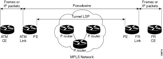
Layer 2 transport over MPLS and IP already exists for like-to-like attachment circuits, such as Ethernet-to-Ethernet or PPP-to-PPP. L2VPN Interworking builds on this functionality by allowing disparate attachment circuits to be connected. An interworking function facilitates the translation between the different Layer 2 encapsulations. Figure 1 is an example of Layer 2 interworking, where ATM and Frame Relay packets travel over the MPLS cloud.
Figure 1 ATM to Frame Relay Interworking Example
The L2VPN Interworking feature supports Ethernet, 802.1Q (VLAN), Frame Relay, ATM AAL5, and PPP attachment circuits over MPLS and L2TPv3. The features and restrictions for like-to-like functionality also apply to L2VPN Interworking.
L2VPN Interworking Modes
L2VPN Interworking works in either Ethernet ("bridged") mode or IP ("routed") mode. You specify the mode by issuing the interworking {ethernet | ip} command in pseudowire-class configuration mode.
The interworking command causes the attachment circuits to be terminated locally. The two keywords perform the following functions:
•
The ethernet keyword causes Ethernet frames to be extracted from the attachment circuit and sent over the pseudowire. Ethernet end-to-end transmission is assumed. Attachment circuit frames that are not Ethernet are dropped. In the case of VLAN, the VLAN tag is removed, leaving an untagged Ethernet frame.
•
The ip keyword causes IP packets to be extracted from the attachment circuit and sent over the pseudowire. Attachment circuit frames that do not contain IPv4 packets are dropped.
The supported L2VPN Interworking features are listed in Table 4.
Table 4 L2VPN Interworking Supported Features
Feature
|
MPLS or L2TPv3 Support
|
IP or Ethernet Support
|
Ethernet/VLAN to ATM AAL5
|
MPLS L2TPv3 (12000 series only)
|
IP Ethernet
|
Ethernet/VLAN to Frame Relay
|
MPLS L2TPv3
|
IP Ethernet
|
Ethernet/VLAN to PPP
|
MPLS
|
IP
|
Ethernet to VLAN
|
MPLS L2TPv3
|
IP Ethernet
|
Frame Relay to ATM AAL5
|
MPLS L2TPv3 (12000 series only)
|
IP
|
Frame Relay to Ethernet or VLAN
|
MPLS L2TPv3
|
IP Ethernet
|
Frame Relay to PPP
|
MPLS L2TPv3
|
IP
|
Note: On the Cisco 12000 series Internet router:
• Ethernet (bridged) interworking is not supported for L2TPv3.
• IP (routed) interworking is not supported in an L2TPv3 pseudowire configured for data sequencing (using the sequencing command).
|
Note
The Cisco 7600 series routers do not support L2VPN Interworking over L2TPv3.
The following sections explain more about Ethernet and IP interworking modes.
Ethernet Interworking
As mentioned earlier, Ethernet Interworking is also called bridged interworking. Ethernet frames are bridged across the pseudowire. The CE routers could be natively bridging Ethernet or could be routing using a bridged encapsulation model, such as Bridge Virtual Interface (BVI) or RBE. The PE routers operate in Ethernet like-to-like mode.
This mode is used to offer the following services:
•
LAN services—An example is an enterprise that has several sites, where some sites have Ethernet connectivity to the service provider (SP) network and others have ATM connectivity. The enterprise wants LAN connectivity to all its sites. In this case, traffic from the Ethernet or VLAN of one site can be sent through the IP/MPLS network and encapsulated as bridged traffic over an ATM VCof another site.
•
Connectivity services—An example is an enterprise that has different sites that are running an Internal Gateway Protocol (IGP) routing protocol, which has incompatible procedures on broadcast and nonbroadcast links. The enterprise has several sites that are running an IGP, such as Open Shortest Path First (OSPF) or Intermediate System to Intermediate System (IS-IS), between the sites. In this scenario, some of the procedures (such as route advertisement or designated router) depend on the underlying Layer 2 protocol and are different for a point-to-point ATM connection versus a broadcast Ethernet connection. Therefore, the bridged encapsulation over ATM can be used to achieve homogenous Ethernet connectivity between the CE routers running the IGP.
IP Interworking
IP Interworking is also called routed interworking. The CE routers encapsulate IP on the link between the CE and PE routers. A new VC type is used to signal the IP pseudowire in MPLS and L2TPv3. Translation between the Layer 2 and IP encapsulations across the pseudowire is required. Special consideration needs to be given to address resolution and routing protocol operation, because these are handled differently on different Layer 2 encapsulations.
This mode is used to provide IP connectivity between sites, regardless of the Layer 2 connectivity to these sites. It is different from a layer 3 VPN because it is point-to-point in nature and the service provider does not maintain any customer routing information.
Address resolution is encapsulation dependent:
•
Ethernet uses ARP
•
Frame Relay and ATM use Inverse ARP
•
PPP uses IPCP
Therefore, address resolution must be terminated on the PE router. End-to-end address resolution is not supported.
Routing protocols operate differently over broadcast and point-to-point media. For Ethernet, the CE routers must either use static routing or configure the routing protocols to treat the Ethernet side as a point-to-point network.
How to Configure L2VPN Interworking
The following sections explain the tasks you can perform to configure L2VPN Interworking:
•
Configuring L2VPN Interworking (required)
•
Configuring Static IP Addresses for L2VPN Interworking for PPP (optional)
•
Verifying the L2VPN Interworking Configuration (optional)
Configuring L2VPN Interworking
Configuring the L2VPN Interworking feature requires that you add the interworking command to the list of commands that comprise the pseudowire. The steps for configuring the pseudowire for L2VPN Interworking are included in this section. You use the interworking command as part of the overall AToM or L2TPv3 configuration. For specific instructions on configuring Any Transport over MPLS (AToM) or L2TPv3, see the following documents:
•
Layer 2 Tunnel Protocol Version 3
•
Any Transport over MPLS
SUMMARY STEPS
1.
enable
2.
configure terminal
3.
hw-module slot slot-number np mode feature
4.
pseudowire-class name
5.
encapsulation {mpls | l2tpv3}
6.
interworking {ethernet | ip}
DETAILED STEPS
| |
Command or Action
|
Purpose
|
Step 1
|
enable
Example:
Router> enable
|
Enables privileged EXEC mode.
• Enter your password if prompted.
|
Step 2
|
configure terminal
Example:
Router# configure terminal
|
Enters global configuration mode.
|
Step 3
|
hw-module slot slot-number np mode feature
Example:
Router(config)# hw-module slot 3 np mode
feature
|
(Optional) Enter this command only on a Cisco 12000 series Internet router if you use L2TPv3 for L2VPN Interworking on an ISE (Engine 3) or Engine 5 interface.
In this case, you must first enable the L2VPN feature bundle on the line card by entering the hw-module slot slot-number np mode feature command.
|
Step 4
|
pseudowire-class name
Example:
Router(config)# pseudowire-class class1
|
Establishes a pseudowire class with a name that you specify and enters pseudowire class configuration mode.
|
Step 5
|
encapsulation {mpls | l2tpv3}
Example:
Router(config-pw)# encapsulation mpls
|
Specifies the tunneling encapsulation, which is either mpls or l2tpv3.
|
Step 6
|
interworking {ethernet | ip}
Example:
Router(config-pw)# interworking ip
|
Specifies the type of pseudowire and the type of traffic that can flow across it.
Note On the Cisco 12000 series Internet router, Ethernet (bridged) interworking is not supported for L2TPv3. After you configure the L2TPv3 tunnel encapsulation for the pseudowire using the encapsulation l2tpv3 command, you cannot enter the interworking ethernet command.
|
Configuring Static IP Addresses for L2VPN Interworking for PPP
If the PE router needs to perform address resolution with the local CE router for PPP, you can configure the remote CE router's IP address on the PE router. Issue the ppp ipcp address proxy command with the remote CE router's IP address on the PE router's xconnect PPP interface. The following example shows a sample configuration:
pseudowire-class ip-interworking
xconnect 10.0.0.2 200 pw-class ip-interworking
ppp ipcp address proxy 10.65.32.14
You can also configure the remote CE router's IP address on the local CE router with the peer default ip address command if the local CE router performs address resolution.
Verifying the L2VPN Interworking Configuration
To verify the L2VPN Interworking configuration, you can use the following commands.
SUMMARY STEPS
1.
show l2tun session all (L2TPv3 only)
2.
show arp
3.
ping
4.
show l2tun session interworking (L2TPv3 only)
5.
show mpls l2transport vc detail (AToM only)
DETAILED STEPS
Step 1
show l2tun session all (L2TPv3 only)
For L2TPv3, you can verify the L2VPN Interworking configuration using the show l2tun session all command on the PE routers. In the following example, the interworking type is shown in bold.
PE1
|
PE2
|
Router# show l2tun session all
Session Information Total tunnels 1 sessions 1
Session id 15736 is up, tunnel id 35411
Call serial number is 4035100045
Remote tunnel name is PE2
Internet address is 10.9.9.9
Session is L2TP signalled
Session state is established, time since
change 1d22h
16 Packets sent, 16 received
1518 Bytes sent, 1230 received
Receive packets dropped:
out-of-order: 0
total: 0
Send packets dropped:
exceeded session MTU: 0
total: 0
Session vcid is 123
Session Layer 2 circuit, type is Ethernet,
name is FastEthernet1/1/0
Circuit state is UP
Remote session id is 26570, remote tunnel
id 46882
DF bit off, ToS reflect disabled, ToS value
0, TTL value 255
No session cookie information available
FS cached header information:
encap size = 24 bytes
00000000 00000000 00000000 00000000
00000000 00000000
Sequencing is off
|
Router# show l2tun session all
Session Information Total tunnels 1 sessions 1
Session id 26570 is up, tunnel id 46882
Call serial number is 4035100045
Remote tunnel name is PE1
Internet address is 10.8.8.8
Session is L2TP signalled
Session state is established, time since change 1d22h
16 Packets sent, 16 received
1230 Bytes sent, 1230 received
Receive packets dropped:
out-of-order: 0
total: 0
Send packets dropped:
exceeded session MTU: 0
total: 0
Session vcid is 123
Session Layer 2 circuit, type is Ethernet Vlan, name is
FastEthernet2/0.1:10
Circuit state is UP, interworking type is Ethernet
Remote session id is 15736, remote tunnel id 35411
DF bit off, ToS reflect disabled, ToS value 0, TTL
value 255
No session cookie information available
FS cached header information:
encap size = 24 bytes
00000000 00000000 00000000 00000000
00000000 00000000
Sequencing is off
|
Step 2
show arp
You can issue show arp command between the CE routers to ensure that data is being sent:
Protocol Address Age (min) Hardware Addr Type Interface
Internet 10.1.1.5 134 0005.0032.0854 ARPA FastEthernet0/0
Internet 10.1.1.7 - 0005.0032.0000 ARPA FastEthernet0/0
Step 3
ping
You can issue ping command between the CE routers to ensure that data is being sent:
Type escape sequence to abort.
Sending 5, 100-byte ICMP Echos to 10.1.1.5, timeout is 2 seconds:
Success rate is 100 percent (5/5), round-trip min/avg/max = 1/2/4 ms
Step 4
show l2tun session interworking
To verify that the interworking type is correctly set, use the show l2tun session interworking command. Enter the command on the PE routers that are performing the interworking translation.
•
In Example 1, the PE router performs the raw Ethernet translation. Tthe command output displays the interworking type with a dash (-).
•
In Example 2, the PE router performs the Ethernet VLAN translation. The command output displays the interworking type as ETH.
Example 1 Command Output for Raw Ethernet Translation
Router# show l2tun session interworking
Session Information Total tunnels 1 sessions 1
LocID TunID Peer-address Type IWrk Username, Intf/Vcid, Circuit
15736 35411 10.9.9.9 ETH - 123, Fa1/1/0
Example 2 Command Output for Ethernet VLAN Translation
Router# show l2tun session interworking
Session Information Total tunnels 1 sessions 1
LocID TunID Peer-address Type IWrk Username, Intf/Vcid, Circuit
26570 46882 10.8.8.8 VLAN ETH 123, Fa2/0.1:10
Step 5
show mpls l2transport vc detail
You can verify the AToM configuration by using the show mpls l2transport vc detail command. In the following example, the interworking type is shown in bold.
PE1
|
PE2
|
Router# show mpls l2transport vc detail
Local interface: Fa1/1/0 up, line protocol up,
Ethernet up
Destination address: 10.9.9.9, VC ID: 123, VC
status: up
Preferred path: not configured
Default path: active
Tunnel label: 17, next hop 10.1.1.3
Output interface: Fa4/0/0, imposed label
stack {17 20}
Create time: 01:43:50, last status change time:
01:43:33
Signaling protocol: LDP, peer 10.9.9.9:0 up
MPLS VC labels: local 16, remote 20
Group ID: local 0, remote 0
MTU: local 1500, remote 1500
Remote interface description:
Sequencing: receive disabled, send disabled
VC statistics:
packet totals: receive 15, send 4184
byte totals: receive 1830, send 309248
packet drops: receive 0, send 0
|
Router# show mpls l2transport vc detail
Local interface: Fa2/0.3 up, line protocol up, Eth VLAN
10 up
MPLS VC type is Ethernet, interworking type is
Ethernet
Destination address: 10.8.8.8, VC ID: 123, VC status:
up
Preferred path: not configured
Default path: active
Tunnel label: 16, next hop 10.1.1.3
Output interface: Fa6/0, imposed label stack {16 16}
Create time: 00:00:26, last status change time:
00:00:06
Signaling protocol: LDP, peer 10.8.8.8:0 up
MPLS VC labels: local 20, remote 16
Group ID: local 0, remote 0
MTU: local 1500, remote 1500
Remote interface description:
Sequencing: receive disabled, send disabled
VC statistics:
packet totals: receive 5, send 0
byte totals: receive 340, send 0
packet drops: receive 0, send 0
|
Configuration Examples for L2VPN Interworking
The following sections show examples of L2VPN Interworking:
•
Ethernet to VLAN over L2TPV3 (Bridged): Example
•
Ethernet to VLAN over AToM (Bridged): Example
•
Frame Relay to VLAN over L2TPV3 (Routed): Example
•
Frame Relay to VLAN over AToM (Routed): Example
•
Frame Relay to ATM AAL5 over AToM (Routed): Example
•
VLAN to ATM AAL5 over AToM (Bridged): Example
•
Frame Relay to PPP over L2TPv3 (Routed): Example
•
Frame Relay to PPP over AToM (Routed): Example
•
Ethernet/VLAN to PPP over AToM (Routed): Example
Ethernet to VLAN over L2TPV3 (Bridged): Example
The following example shows the configuration of Ethernet to VLAN over L2TPv3:
PE1
|
PE2
|
ip cef
!
l2tp-class interworking-class
authentication
hostname PE1
password 0 lab
!
pseudowire-class inter-ether-vlan
encapsulation l2tpv3
interworking ethernet
protocol l2tpv3 interworking-class
ip local interface Loopback0
!
interface Loopback0
ip address 10.8.8.8 255.255.255.255
!
interface FastEthernet1/0
xconnect 10.9.9.9 1 pw-class inter-ether-vlan
|
ip cef
!
l2tp-class interworking-class
authentication
hostname PE2
password 0 lab
!
pseudowire-class inter-ether-vlan
encapsulation l2tpv3
interworking ethernet
protocol l2tpv3 interworking-class
ip local interface Loopback0
!
interface Loopback0
ip address 10.9.9.9 255.255.255.255
!
interface FastEthernet0/0
no ip address
!
interface FastEthernet0/0.3
encapsulation dot1Q 10
xconnect 10.8.8.8 1 pw-class inter-ether-vlan
|
Ethernet to VLAN over AToM (Bridged): Example
The following example shows the configuration of Ethernet to VLAN over AToM:
PE1
|
PE2
|
ip cef
!
mpls label protocol ldp
mpls ldp router-id Loopback0 force
!
pseudowire-class atom-eth-iw
encapsulation mpls
interworking ethernet
!
interface Loopback0
ip address 10.8.8.8 255.255.255.255
!
interface FastEthernet1/0.1
encapsulation dot1q 100
xconnect 10.9.9.9 123 pw-class atom-eth-iw
|
ip cef
!
mpls label protocol ldp
mpls ldp router-id Loopback0 force
!
pseudowire-class atom
encapsulation mpls
!
interface Loopback0
ip address 10.9.9.9 255.255.255.255
!
interface FastEthernet0/0
no ip address
!
interface FastEthernet1/0
xconnect 10.9.9.9 123 pw-class atom
|
Frame Relay to VLAN over L2TPV3 (Routed): Example
PE1
|
PE2
|
configure terminal
ip cef
frame-relay switching
!
!
interface loopback 0
ip address 10.8.8.8 255.255.255.255
no shutdown
!
pseudowire-class ip
encapsulation l2tpv3
interworking ip
ip local interface loopback0
!
interface POS1/0
encapsulation frame-relay
clock source internal
logging event dlci-status-change
no shutdown
no fair-queue
!
connect fr-vlan POS1/0 206 l2transport
xconnect 10.9.9.9 6 pw-class ip
!
router ospf 10
network 10.0.0.2 0.0.0.0 area 0
network 10.8.8.8 0.0.0.0 area 0
|
configure terminal
ip routing
ip cef
frame-relay switching
!
interface loopback 0
ip address 10.9.9.9 255.255.255.255
no shutdown
!
pseudowire-class ip
encapsulation l2tpv3
interworking ip
ip local interface loopback0
!
interface FastEthernet1/0/1
speed 10
no shutdown
!
interface FastEthernet1/0/1.6
encapsulation dot1Q 6
xconnect 10.8.8.8 6 pw-class ip
no shutdown
!
router ospf 10
network 10.0.0.2 0.0.0.0 area 0
network 10.9.9.9 0.0.0.0 area 0
|
The following example shows the configuration of Frame Relay to VLAN over L2TPv3:
Frame Relay to VLAN over AToM (Routed): Example
The following example shows the configuration of Frame Relay to VLAN over AToM:
PE1
|
PE2
|
configure terminal
ip cef
frame-relay switching
!
mpls label protocol ldp
mpls ldp router-id loopback0
mpls ip
!
pseudowire-class atom
encapsulation mpls
interworking ip
!
interface loopback 0
ip address 10.8.8.8 255.255.255.255
no shutdown
!
connect fr-vlan POS1/0 206 l2transport
xconnect 10.9.9.9 6 pw-class atom
|
configure terminal
ip routing
ip cef
frame-relay switching
!
mpls label protocol ldp
mpls ldp router-id loopback0
mpls ip
!
pseudowire-class atom
encapsulation mpls
interworking ip
!
interface loopback 0
ip address 10.9.9.9 255.255.255.255
no shutdown
!
interface FastEthernet1/0/1.6
encapsulation dot1Q 6
xconnect 10.8.8.8 6 pw-class atom
no shutdown
|
Frame Relay to ATM AAL5 over AToM (Routed): Example
Note
Frame Relay to ATM AAL5 is available only with AToM in IP mode.
The following example shows the configuration of Frame Relay to ATM AAL5 over AToM:
PE1
|
PE2
|
ip cef
frame-relay switching
mpls ip
mpls label protocol ldp
mpls ldp router-id loopback0 force
pseudowire-class fratmip
encapsulation mpls
interworking ip
interface Loopback0
ip address 10.33.33.33 255.255.255.255
interface serial 2/0
encapsulation frame-relay ietf
frame-relay intf-type dce
connect fr-eth serial 2/0 100 l2transport
xconnect 10.22.22.22 333 pw-class fratmip
interface POS1/0
ip address 10.1.7.3 255.255.255.0
crc 32
clock source internal
mpls ip
mpls label protocol ldp
router ospf 10
passive-interface Loopback0
network 10.33.33.33 0.0.0.0 area 10
network 10.1.7.0 0.0.0.255 area 10
|
ip cef
mpls ip
mpls label protocol ldp
mpls ldp router-id loopback0 force
pseudowire-class fratmip
encapsulation mpls
interworking ip
interface Loopback0
ip address 10.22.22.22 255.255.255.255
interface ATM 2/0
pvc 0/203 l2transport
encapsulation aa5snap
xconnect 10.33.33.33 333 pw-class fratmip
interface POS1/0
ip address 10.1.1.2 255.255.255.0
crc 32
clock source internal
mpls ip
mpls label protocol ldp
router ospf 10
passive-interface Loopback0
network 10.22.22.22 0.0.0.0 area 10
network 10.1.1.0 0.0.0.255 area 10
|
VLAN to ATM AAL5 over AToM (Bridged): Example
The following example shows the configuration of VLAN to ATM AAL5 over AToM:
PE1
|
PE2
|
ip cef
!
mpls ip
mpls label protocol ldp
mpls ldp router-id Loopback0
!
pseudowire-class inter-ether
encapsulation mpls
interworking ethernet
!
interface Loopback0
ip address 10.8.8.8 255.255.255.255
!
interface ATM1/0.1 point-to-point
pvc 0/100 l2transport
encapsulation aal5snap
xconnect 10.9.9.9 123 pw-class inter-ether
!
interface FastEthernet1/0
xconnect 10.9.9.9 1 pw-class inter-ether
!
router ospf 10
log-adjacency-changes
network 10.8.8.8 0.0.0.0 area 0
network 10.1.1.1 0.0.0.0 area 0
|
ip cef
!
mpls ip
mpls label protocol ldp
mpls ldp router-id Loopback0
!
pseudowire-class inter-ether
encapsulation mpls
interworking ethernet
!
interface Loopback0
ip address 10.9.9.9 255.255.255.255
!
interface FastEthernet0/0
no ip address
!
interface FastEthernet0/0.1
encapsulation dot1Q 10
xconnect 10.8.8.8 123 pw-class inter-ether
!
router ospf 10
log-adjacency-changes
network 10.9.9.9 0.0.0.0 area 0
network 10.1.1.2 0.0.0.0 area 0
|
Frame Relay to PPP over L2TPv3 (Routed): Example
The following example shows the configuration of Frame Relay to PPP over L2TPv3:
PE1
|
PE2
|
ip cef
ip routing
!
!
!
pseudowire-class ppp-fr
encapsulation l2tpv3
interworking ip
ip local interface Loopback0
!
interface Loopback0
ip address 10.1.1.1 255.255.255.255
!
interface FastEthernet1/0/0
ip address 10.16.1.1 255.255.255.0
!
interface Serial3/0/0
no ip address
encapsulation ppp
ppp authentication chap
!
ip route 10.0.0.0 255.0.0.0 10.16.1.2
!
xconnect 10.2.2.2 1 pw-class ppp-fr
ppp ipcp address proxy 10.65.32.14
|
ip cef
ip routing
!
frame-relay switching
!
pseudowire-class ppp-fr
encapsulation l2tpv3
interworking ip
ip local interface Loopback0
!
interface Loopback0
ip address 10.2.2.2 255.255.255.255
!
interface FastEthernet1/0/0
ip address 10.16.2.1 255.255.255.0
!
interface Serial3/0/0
no ip address
encapsulation frame-relay
frame-relay intf-type dce
!
ip route 10.0.0.0 255.0.0.0 10.16.2.2
!
connect ppp-fr Serial3/0/0 100 l2transport
xconnect 10.1.1.1 100 pw-class ppp-fr
|
Frame Relay to PPP over AToM (Routed): Example
The following example shows the configuration of Frame Relay to PPP over AToM:
PE1
|
PE2
|
ip cef
ip routing
mpls label protocol ldp
mpls ldp router-id loopback0 force
!
!
!
pseudowire-class ppp-fr
encapsulation mpls
interworking ip
ip local interface Loopback0
!
interface Loopback0
ip address 10.1.1.1 255.255.255.255
!
interface FastEthernet1/0/0
ip address 10.16.1.1 255.255.255.0
mpls ip
label protocol ldp
!
interface Serial3/0/0
no ip address
encapsulation ppp
ppp authentication chap
xconnect 10.2.2.2 1 pw-class ppp-fr
ppp ipcp address proxy 10.65.32.14
!
ip route 10.0.0.0 255.0.0.0 10.16.1.2
|
ip cef
ip routing
mpls label protocol ldp
mpls ldp router-id loopback0 force
!
frame-relay switching
!
pseudowire-class ppp-fr
encapsulation mpls
interworking ip
ip local interface Loopback0
!
interface Loopback0
ip address 10.2.2.2 255.255.255.255
!
interface FastEthernet1/0/0
ip address 10.16.2.1 255.255.255.0
mpls ip
mpls label protocol ldp
!
interface Serial3/0/0
no ip address
encapsulation frame-relay
frame-relay intf-type dce
!
ip route 10.0.0.0 255.0.0.0 10.16.2.2
!
connect ppp-fr Serial3/0/0 100 l2transport
xconnect 10.1.1.1 100 pw-class ppp-fr
|
Ethernet/VLAN to PPP over AToM (Routed): Example
The following example shows the configuration of Ethernet VLAN to PPP over AToM:
PE1
|
PE2
|
configure terminal
mpls label protocol ldp
mpls ldp router-id Loopback0
mpls ip
!
pseudowire-class ppp-ether
encapsulation mpls
interworking ip
!
interface Loopback0
ip address 10.8.8.8 255.255.255.255
no shutdown
!
interface POS2/0/1
no ip address
encapsulation ppp
no peer default ip address
ppp ipcp address proxy 10.10.10.1
xconnect 10.9.9.9 300 pw-class ppp-ether
no shutdown
|
configure terminal
mpls label protocol ldp
mpls ldp router-id Loopback0
mpls ip
!
pseudowire-class ppp-ether
encapsulation mpls
interworking ip
!
interface Loopback0
ip address 10.9.9.9 255.255.255.255
no shutdown
!
interface vlan300
mtu 4470
no ip address
xconnect 10.8.8.8 300 pw-class ppp-ether
no shutdown
!
interface GigabitEthernet6/2
switchport
switchport trunk encapsulation dot1q
switchport trunk allowed vlan 300
switchport mode trunk
no shut
|
Additional References
The following sections provide references related to the L2VPN Interworking feature.
Related Documents
Standards
Standards
|
Title
|
draft-ietf-l2tpext-l2tp-base-03.txt
|
Layer Two Tunneling Protocol (Version 3) 'L2TPv3'
|
draft-martini-l2circuit-trans-mpls-09.txt
|
Transport of Layer 2 Frames Over MPLS
|
draft-ietf-pwe3-frame-relay-03.txt.
|
Encapsulation Methods for Transport of Frame Relay over MPLS Networks
|
draft-martini-l2circuit-encap-mpls-04.txt.
|
Encapsulation Methods for Transport of Layer 2 Frames Over IP and MPLS Networks
|
draft-ietf-pwe3-ethernet-encap-08.txt.
|
Encapsulation Methods for Transport of Ethernet over MPLS Networks
|
draft-ietf-pwe3-hdlc-ppp-encap-mpls-03.txt.
|
Encapsulation Methods for Transport of PPP/HDLC over MPLS Networks
|
draft-ietf-ppvpn-l2vpn-00.txt.
|
An Architecture for L2VPNs
|
MIBs
MIBs
|
MIBs Link
|
No new or modified MIBs are supported by this feature, and support for existing MIBs has not been modified by this feature.
|
To locate and download MIBs for selected platforms, Cisco IOS releases, and feature sets, use Cisco MIB Locator found at the following URL:
http://www.cisco.com/go/mibs
|
RFCs
RFCs
|
Title
|
No new or modified RFCs are supported by this feature, and support for existing RFCs has not been modified by this feature.
|
—
|
Technical Assistance
Description
|
Link
|
The Cisco Technical Support & Documentation website contains thousands of pages of searchable technical content, including links to products, technologies, solutions, technical tips, tools, and technical documentation. Registered Cisco.com users can log in from this page to access even more content.
|
http://www.cisco.com/techsupport
|
Command Reference
This section documents new and modified commands.
•
debug frame-relay pseudowire
•
debug ssm
•
interworking
•
mtu
•
show l2tun session
•
show l2tun tunnel
•
show mpls l2transport vc
debug frame-relay pseudowire
To display events and error conditions that occur when binding a Frame Relay data-link connection identifier (DLCI) to a pseudowire, use the debug frame-relay pseudowire command in privileged EXEC mode. To disable the display of these events and error conditions, use the no form of this command.
debug frame-relay pseudowire
no debug frame-relay pseudowire
Syntax Description
This command contains no arguments or keywords.
Defaults
DLCI events and errors are not displayed.
Command Modes
Privileged EXEC
Command History
Release
|
Modification
|
12.0(26)S
|
This command was introduced.
|
12.2(25)S
|
This command was integrated into Cisco IOS Release 12.2(25)S.
|
12.2(33)SRA
|
This command was integrated into Cisco IOS Release 12.2(33)SRA.
|
12.4(11)T
|
This command was integrated into Cisco IOS Release 12.4(11)T.
|
Usage Guidelines
The following are examples of Frame Relay pseudowire events:
•
Command-line interface (CLI) provisioning events
•
Pseudowire circuit status updates
•
Failures occurring during the management of these events
Examples
The following example enables the display of Frame Relay pseudowire events. In this example, the interface has been shut down and then enabled.
Router# debug frame-relay pseudowire
Router(config)# interface hssi1/0/0
Router(config-if)# shutdown
09:18:33.303: FRoPW [10.15.15.15, 100]: acmgr_circuit_down
09:18:33.303: FRoPW [10.15.15.15, 100]: SW AC update circuit state to down
09:18:33.303: FRoPW [10.15.15.15, 100]: Setting connection DOWN
09:18:35.299: %LINK-5-CHANGED: Interface Hssi1/0/0, changed state to administratively down
09:18:36.299: %LINEPROTO-5-UPDOWN: Line protocol on Interface Hssi1/0/0, changed state to
down
Router(config-if)# no shutdown
09:18:41.919: %LINK-3-UPDOWN: Interface Hssi1/0/0, changed state to up
09:18:41.919: FRoPW [10.15.15.15, 100]: Local up, sending acmgr_circuit_up
09:18:41.919: FRoPW [10.15.15.15, 100]: Setting pw segment UP
09:18:41.919: FRoPW [10.15.15.15, 100]: PW nni_pvc_status set ACTIVE
09:18:41.919: label_oce_get_label_bundle: flags 14 label 28
09:18:42.919: %LINEPROTO-5-UPDOWN: Line protocol on Interface Hssi1/0/0, changed state to
up
Table 5 describes the significant fields shown in the display.
Table 5 debug frame-relay pseudowire Field Descriptions
Field
|
Description
|
Time (09.18.41)
|
When the event occurred (in hours, minutes, and seconds).
|
[10.15.15.15, 100]
|
10.15.15.15 is the IP address of the peer provider edge (PE) router.
100 is the DLCI number of the Frame Relay permanent virtual circuit (PVC) used for this pseudowire.
|
debug ssm
To display diagnostic information about the Segment Switching Manager (SSM) for switched Layer 2 segments, use the debug ssm command in privileged EXEC mode. To disable debugging, use the no form of this command.
debug ssm {cm errors | cm events | fhm errors | fhm events | sm errors | sm events | sm counters
| xdr}
no debug ssm {cm errors | cm events | fhm errors | fhm events | sm errors | sm events | sm
counters | xdr}
Syntax Description
cm errors
|
Displays Connection Manager (CM) errors.
|
cm events
|
Displays CM events.
|
fhm errors
|
Displays Feature Handler Manager (FHM) errors.
|
fhm events
|
Displays FHM events.
|
sm errors
|
Displays Segment Handler Manager (SM) errors.
|
sm events
|
Displays SM events.
|
sm counters
|
Displays SM counters.
|
xdr
|
Displays external data representation (XDR) messages related to traffic sent across the backplane between Router Processors and line cards.
|
Defaults
SSM events and errors are not displayed.
Command Modes
Privileged EXEC
Command History
Release
|
Modification
|
12.0(26)S
|
This command was introduced.
|
12.2(25)S
|
This command was integrated into Cisco IOS Release 12.2(25)S.
|
12.2(28)SB
|
This command was integrated into Cisco IOS Release 12.2(28)SB.
|
12.2(33)SRA
|
This command was integrated into Cisco IOS Release 12.2(33)SRA.
|
12.4(11)T
|
This command was integrated into Cisco IOS Release 12.4(11)T.
|
Usage Guidelines
The SSM manages the data-plane component of the Layer 2 Virtual Private Network (L2VPN) configuration. The CM tracks the connection-level errors and events that occur on an xconnect. The SM tracks the per-segment events and errors on the xconnect.
Use the debug ssm command to troubleshoot problems in bringing up the data plane.
This command is generally used only by Cisco engineers for internal debugging of SSM processes.
Examples
The following example shows sample output for the debug ssm xdr command:
2w5d: SSM XDR: [4096] deallocate segment, len 16
2w5d: SSM XDR: [8193] deallocate segment, len 16
2w5d: %LINK-3-UPDOWN: Interface FastEthernet2/1, changed state to down
2w5d: %LINK-3-UPDOWN: Interface FastEthernet2/1, changed state to up
2w5d: SSM XDR: [4102] provision segment, switch 4101, len 106
2w5d: SSM XDR: [4102] update segment status, len 17
2w5d: SSM XDR: [8199] provision segment, switch 4101, len 206
2w5d: SSM XDR: [4102] update segment status, len 17
2w5d: %SYS-5-CONFIG_I: Configured from console by console
2w5d: %LINK-3-UPDOWN: Interface FastEthernet2/1, changed state to down
2w5d: SSM XDR: [4102] update segment status, len 17
2w5d: %LINK-3-UPDOWN: Interface FastEthernet2/1, changed state to up
2w5d: SSM XDR: [4102] deallocate segment, len 16
2w5d: SSM XDR: [8199] deallocate segment, len 16
2w5d: SSM XDR: [4104] provision segment, switch 4102, len 106
2w5d: SSM XDR: [4104] update segment status, len 17
2w5d: SSM XDR: [8201] provision segment, switch 4102, len 206
2w5d: SSM XDR: [4104] update segment status, len 17
2w5d: %SYS-5-CONFIG_I: Configured from console by console
The following example shows the events that occur on the segment manager when an Any Transport over MPLS (AToM) virtual circuit (VC) configured for Ethernet over MPLS is shut down and then enabled:
Router# debug ssm sm events
SSM Connection Manager events debugging is on
Router(config)# interface fastethernet 0/1/0.1
Router(config-subif)# shutdown
09:13:38.159: SSM SM: [SSS:AToM:36928] event Unprovison segment
09:13:38.159: SSM SM: [SSS:Ethernet Vlan:4146] event Unbind segment
09:13:38.159: SSM SM: [SSS:AToM:36928] free segment class
09:13:38.159: SSM SM: [SSS:AToM:36928] free segment
09:13:38.159: SSM SM: [SSS:AToM:36928] event Free segment
09:13:38.159: SSM SM: last segment class freed
09:13:38.159: SSM SM: [SSS:Ethernet Vlan:4146] segment ready
09:13:38.159: SSM SM: [SSS:Ethernet Vlan:4146] event Found segment data
Router(config-subif)# no shutdown
09:13:45.815: SSM SM: [SSS:AToM:36929] event Provison segment
09:13:45.815: label_oce_get_label_bundle: flags 14 label 16
09:13:45.815: SSM SM: [SSS:AToM:36929] segment ready
09:13:45.815: SSM SM: [SSS:AToM:36929] event Found segment data
09:13:45.815: SSM SM: [SSS:AToM:36929] event Bind segment
09:13:45.815: SSM SM: [SSS:Ethernet Vlan:4146] event Bind segment
The following example shows the events that occur on the CM when an AToM VC configured for Ethernet over MPLS is shut down and then enabled:
Router(config)# interface fastethernet 0/1/0.1
Router(config-subif)# shutdown
09:17:20.179: SSM CM: [AToM] unprovision segment, id 36929
09:17:20.179: SSM CM: CM FSM: state Open - event Free segment
09:17:20.179: SSM CM: [SSS:AToM:36929] unprovision segment 1
09:17:20.179: SSM CM: [SSS:AToM] shQ request send unprovision complete event
09:17:20.179: SSM CM: [SSS:Ethernet Vlan:4146] unbind segment 2
09:17:20.179: SSM CM: [SSS:Ethernet Vlan] shQ request send ready event
09:17:20.179: SSM CM: SM msg event send unprovision complete event
09:17:20.179: SSM CM: SM msg event send ready event
Router(config-subif)# no shutdown
09:17:35.879: SSM CM: Query AToM to Ethernet Vlan switching, enabled
09:17:35.879: SSM CM: [AToM] provision second segment, id 36930
09:17:35.879: SSM CM: CM FSM: state Down - event Provision segment
09:17:35.879: SSM CM: [SSS:AToM:36930] provision segment 2
09:17:35.879: SSM CM: [AToM] send client event 6, id 36930
09:17:35.879: SSM CM: [SSS:AToM] shQ request send ready event
09:17:35.883: SSM CM: SM msg event send ready event
09:17:35.883: SSM CM: [AToM] send client event 3, id 36930
The following example shows the events that occur on the CM and SM when an AToM VC is provisioned and then unprovisioned:
Router# debug ssm cm events
SSM Connection Manager events debugging is on
Router# debug ssm sm events
SSM Segment Manager events debugging is on
Router# configure terminal
Router(config)# interface ethernet1/0
Router(config-if)# xconnect 10.55.55.2 101 pw-class mpls
16:57:34: SSM CM: provision switch event, switch id 86040
16:57:34: SSM CM: [Ethernet] provision first segment, id 12313
16:57:34: SSM CM: CM FSM: state Idle - event Provision segment
16:57:34: SSM CM: [SSS:Ethernet:12313] provision segment 1
16:57:34: SSM SM: [SSS:Ethernet:12313] event Provison segment
16:57:34: SSM CM: [SSS:Ethernet] shQ request send ready event
16:57:34: SSM CM: SM msg event send ready event
16:57:34: SSM SM: [SSS:Ethernet:12313] segment ready
16:57:34: SSM SM: [SSS:Ethernet:12313] event Found segment data
16:57:34: SSM CM: Query AToM to Ethernet switching, enabled
16:57:34: SSM CM: [AToM] provision second segment, id 16410
16:57:34: SSM CM: CM FSM: state Down - event Provision segment
16:57:34: SSM CM: [SSS:AToM:16410] provision segment 2
16:57:34: SSM SM: [SSS:AToM:16410] event Provison segment
16:57:34: SSM CM: [AToM] send client event 6, id 16410
16:57:34: label_oce_get_label_bundle: flags 14 label 19
16:57:34: SSM CM: [SSS:AToM] shQ request send ready event
16:57:34: SSM CM: SM msg event send ready event
16:57:34: SSM SM: [SSS:AToM:16410] segment ready
16:57:34: SSM SM: [SSS:AToM:16410] event Found segment data
16:57:34: SSM SM: [SSS:AToM:16410] event Bind segment
16:57:34: SSM SM: [SSS:Ethernet:12313] event Bind segment
16:57:34: SSM CM: [AToM] send client event 3, id 16410
Router# configure terminal
Router(config)# interface e1/0
Router(config-if)# no xconnect
16:57:26: SSM CM: [Ethernet] unprovision segment, id 16387
16:57:26: SSM CM: CM FSM: state Open - event Free segment
16:57:26: SSM CM: [SSS:Ethernet:16387] unprovision segment 1
16:57:26: SSM SM: [SSS:Ethernet:16387] event Unprovison segment
16:57:26: SSM CM: [SSS:Ethernet] shQ request send unprovision complete event
16:57:26: SSM CM: [SSS:AToM:86036] unbind segment 2
16:57:26: SSM SM: [SSS:AToM:86036] event Unbind segment
16:57:26: SSM CM: SM msg event send unprovision complete event
16:57:26: SSM SM: [SSS:Ethernet:16387] free segment class
16:57:26: SSM SM: [SSS:Ethernet:16387] free segment
16:57:26: SSM SM: [SSS:Ethernet:16387] event Free segment
16:57:26: SSM SM: last segment class freed
16:57:26: SSM CM: unprovision switch event, switch id 12290
16:57:26: SSM CM: [SSS:AToM] shQ request send unready event
16:57:26: SSM CM: SM msg event send unready event
16:57:26: SSM SM: [SSS:AToM:86036] event Unbind segment
16:57:26: SSM CM: [AToM] unprovision segment, id 86036
16:57:26: SSM CM: CM FSM: state Down - event Free segment
16:57:26: SSM CM: [SSS:AToM:86036] unprovision segment 2
16:57:26: SSM SM: [SSS:AToM:86036] event Unprovison segment
16:57:26: SSM CM: [SSS:AToM] shQ request send unprovision complete event
16:57:26: SSM CM: SM msg event send unprovision complete event
16:57:26: SSM SM: [SSS:AToM:86036] free segment class
16:57:26: SSM SM: [SSS:AToM:86036] free segment
16:57:26: SSM SM: [SSS:AToM:86036] event Free segment
16:57:26: SSM SM: last segment class freed
Related Commands
Command
|
Description
|
show ssm
|
Displays SSM information for switched Layer 2 segments.
|
interworking
To enable the L2VPN Interworking feature, use the interworking command in pseudowire class configuration mode. To disable the L2VPN Interworking feature, use the no form of this command.
interworking {ethernet | ip}
no interworking {ethernet | ip}
Syntax Description
ethernet
|
Causes Ethernet frames to be extracted from the attachment circuit and sent over the pseudowire. Ethernet end-to-end transmission is assumed. Attachment circuit frames that do not contain Ethernet frames are dropped. In the case of VLAN, the VLAN tag is removed, leaving a pure Ethernet frame.
|
ip
|
Causes IP packets to be extracted from the attachment circuit and sent over the pseudowire. Attachment circuit frames that do not contain IPv4 packets are dropped.
|
Defaults
L2VPN Interworking is not enabled.
Command Modes
Pseudowire class configuration
Command History
Release
|
Modification
|
12.0(26)S
|
This command was introduced.
|
12.2(25)S
|
This command was integrated into Cisco IOS Release 12.2(25)S.
|
12.2(33)SRA
|
This command was integrated into Cisco IOS Release 12.2(33)SRA.
|
12.4(11)T
|
This command was integrated into Cisco IOS Release 12.4(11)T.
|
Usage Guidelines
Table 6 shows which L2VPN Interworking features support Ethernet, IP, or both types of interworking.
Table 6 L2VPN Interworking Feature Support
L2VPN Interworking Feature
|
IP Interworking Support?
|
Ethernet Interworking Support?
|
Frame Relay to PPP
|
Yes
|
No
|
Frame Relay to ATM AAL5
|
Yes
|
No
|
Ethernet/VLAN to ATM AAL5
|
Yes
|
Yes
|
Ethernet/VLAN to Frame Relay
|
Yes
|
Yes
|
Ethernet/VLAN to PPP
|
Yes
|
No
|
Ethernet to VLAN
|
Yes
|
Yes
|
Examples
The following example shows a pseudowire class configuration that enables the L2VPN Interworking feature:
pseudowire-class ip-interworking
Related Commands
Command
|
Description
|
encapsulation l2tpv3
|
Specifies that L2TPv3 is used as the data encapsulation method for tunneling IP traffic over the pseudowire.
|
encapsulation mpls
|
Specifies that MPLS is used as the data encapsulation method for tunneling Layer 2 traffic over the pseudowire.
|
mtu
To adjust the maximum packet size or maximum transmission unit (MTU) size, use the mtu command in interface configuration mode or connect submode. To restore the MTU value to its original default value, use the no form of this command.
mtu bytes
no mtu
Syntax Description
bytes
|
MTU size, in bytes.
|
Defaults
Table 7 lists default MTU values according to media type.
Table 7 Default Media MTU Values
Media Type
|
Default MTU (Bytes)
|
Ethernet
|
1500
|
Serial
|
1500
|
Token Ring
|
4464
|
ATM
|
4470
|
FDDI
|
4470
|
HSSI (HSA)
|
4470
|
Command Modes
Interface configuration
Connect submode (for Frame Relay Layer 2 Interworking)
Command History
Release
|
Modification
|
10.0
|
This command was introduced.
|
12.0(26)S
|
This command was updated to support connect submode for Frame Relay Layer 2 Interworking.
|
12.2(33)SRA
|
This command was integrated into Cisco IOS Release 12.2(33)SRA.
|
12.4(11)T
|
This command was integrated into Cisco IOS Release 12.4(11)T.
|
Usage Guidelines
Each interface has a default maximum packet size or MTU size. This number generally defaults to the largest size possible for that interface type. On serial interfaces, the MTU size varies, but cannot be set to a value less than 64 bytes.
Note
Changing the MTU size is not supported on a loopback interface.
Note
Changing an MTU size on a Cisco 7500 series router results in the recarving of buffers and resetting of all interfaces. The following message is displayed:
%RSP-3-Restart:cbus complex.
Note
You can configure native Gigabit Ethernet ports on the Cisco 7200 series router to a maximum MTU size of 9216 bytes. The MTU values range from 1500 to 9216 bytes.
Protocol-Specific Versions of the mtu Command
Changing the MTU value with the mtu interface configuration command can affect values for the protocol-specific versions of the command (the ip mtu command, for example). If the value specified with the ip mtu interface configuration command is the same as the value specified with the mtu interface configuration command, and you change the value for the mtu interface configuration command, the ip mtu value automatically matches the new mtu interface configuration command value. However, changing the values for the ip mtu configuration commands has no effect on the value for the mtu interface configuration command.
ATM and LANE Interfaces
ATM interfaces are not bound by what is configured on the major interface. By default, MTU on a subinterface is equal to the default MTU (4490); if a client is configured the default is 1500. MTU can be changed on subinterfaces, but it may result in recarving of buffers to accommodate the new maximum MTU on the interface.
Examples
The following example specifies an MTU of 1000 bytes:
Router(config)# interface serial 1
Router(config-if)# mtu 1000
Related Commands
Command
|
Description
|
encapsulation smds
|
Enables SMDS service on the desired interface.
|
ip mtu
|
Sets the MTU size of IP packets sent on an interface.
|
show l2tun session
To display the current state of Layer 2 sessions and protocol information about Layer 2 Tunnel Protocol (L2TP) control channels, use the show l2tun session command in privileged EXEC mode.
show l2tun session [all [filter] | brief [filter] [hostname] | circuit [filter] [hostname] |
interworking [filter] [hostname] | packets [filter] | sequence [filter] | state [filter]]
Syntax Description
all
|
(Optional) Displays information about all current L2TP sessions on the router.
|
filter
|
(Optional) One of the filter parameters defined in Table 8.
|
brief
|
(Optional) Displays information about all current L2TP sessions, including peer ID address and circuit status of the L2TP sessions.
|
hostname
|
(Optional) Specifies that the peer hostname will be displayed in the output.
|
circuit
|
(Optional) Displays information about all current L2TP sessions, including circuit status (up or down).
|
interworking
|
(Optional) Displays information about Layer 2 Virtual Private Network (L2VPN) interworking.
|
packets
|
(Optional) Displays information about the packet counters (in and out) associated with current L2TP sessions.
|
sequence
|
(Optional) Displays sequencing information about each L2TP session, including number of out-of-order and returned packets.
|
state
|
(Optional) Displays information about all current L2TP sessions and their protocol state, including remote Virtual Connection Identifier (VCIDs).
|
Command Modes
Privileged EXEC
Command History
Release
|
Modification
|
12.0(23)S
|
This command was introduced.
|
12.3(2)T
|
This command was integrated into Cisco IOS Release 12.3(2)T.
|
12.2(25)S
|
This command was integrated into Cisco IOS Release 12.2(25)S.
|
12.0(31)S
|
The hostname keyword was added.
|
12.2(27)SBC
|
This command was integrated into Cisco IOS Release 12.2(27)SBC.
|
12.2(33)SRA
|
This command was integrated into Cisco IOS Release 12.2(33)SRA.
|
12.4(11)T
|
This command was integrated into Cisco IOS Release 12.4(11)T.
|
Usage Guidelines
Use the show l2tun session command to display information about current L2TP sessions on the router.
Table 8 defines the filter parameters available to refine the output of the show l2tun session command.
Table 8 Filter Parameters for the show l2tun session Command
Syntax
|
Description
|
ip-addr ip-address [vcid number]
|
Filters the output to display information about only those L2TP sessions associated with the IP address of the peer router. The 32-bit VCID shared between the peer router and the local router at each end of the control channel can optionally be specified.
• ip-address—IP address of the peer router.
• number—The VCID number.
|
vcid number
|
Filters the output to display information about only those L2TP sessions associated with the VCID shared between the peer router and the local router at each end of the control channel.
• number—The VCID number.
|
username username
|
Filters the output to display information for only those sessions associated with the specified username.
• username—The username.
|
Examples
The following example shows how to display detailed information about all current L2TP sessions:
Router# show l2tun session all
Session Information Total tunnels 0 sessions 1
Session id 42438 is down, tunnel id 45795
Remote session id is 0, remote tunnel id 43092
Session Layer 2 circuit, type is Ethernet, name is FastEthernet4/1/1
Session vcid is 123456789
Local circuit state is DOWN
Remote circuit state is DOWN
Call serial number is 1463700128
Remote tunnel name is PE1
Internet address is 10.1.1.1
Internet address is 10.1.1.2
Session is L2TP signalled
Session state is idle, time since change 00:00:26
0 Packets sent, 0 received
Last clearing of "show vpdn" counters never
DF bit off, ToS reflect disabled, ToS value 0, TTL value 255
No session cookie information available
UDP checksums are disabled
No FS cached header information available
The following example shows how to display information only about the L2TP session set up on a peer router with an IP address of 172.16.184.142 and a VCID of 300:
Router# show l2tun session all ip-addr 172.16.184.142 vcid 300
Session id 32518 is up, tunnel id 35217
Call serial number is 2074900020
Remote tunnel name is tun1
Internet address is 172.16.184.142
Session is L2TP signalled
Session state is established, time since change 03:06:39
9932 Packets sent, 9932 received
1171954 Bytes sent, 1171918 received
Session Layer 2 circuit, type is Ethernet Vlan, name is FastEthernet0/1/0.3:3
Remote session id is 18819, remote tunnel id 37340
Session cookie information:
local cookie, size 4 bytes, value CF DC 5B F3
remote cookie, size 4 bytes, value FE 33 56 C4
Ns 9932, Nr 10001, 0 out of order packets discarded
Table 9 describes the significant fields shown in the displays.
Table 9 show l2tun session Field Descriptions
Field
|
Description
|
Total tunnels
|
Total number of L2TP tunnels currently established on the router.
|
sessions
|
Number of L2TP sessions currently established on the router.
|
Session id
|
Session ID for established sessions.
|
is
|
Session state.
|
tunnel id
|
Tunnel ID for established tunnels.
|
Remote session id
|
Session ID for the remote session.
|
Remote tunnel id
|
Tunnel ID for the remote tunnel.
|
Session Layer 2 circuit type is, name is
|
Type and name of the interface used for the Layer 2 circuit.
|
Session vcid is
|
VCID of the session.
|
Circuit state is
|
State of the Layer 2 circuit.
|
Local circuit state is
|
State of the local circuit.
|
Remote circuit state is
|
State of the remote circuit.
|
Call serial number is
|
Call serial number.
|
Remote tunnel name is
|
Name of the remote tunnel.
|
Internet address is
|
IP address of the remote tunnel.
|
Local tunnel name is
|
Name of the local tunnel.
|
Internet address is
|
IP address of the local tunnel.
|
IP protocol
|
The IP protocol used.
|
Session is
|
Signaling type for the session.
|
Session state is
|
Session state for the session.
|
time since change
|
Time since the session state last changed, in the format hh:mm:ss.
|
Packets sent, received
|
Number of packets sent and received since the session was established.
|
Bytes sent, received
|
Number of bytes sent and received since the session was established.
|
Last clearing of "show vpdn" counters
|
Time elapsed since the last clearing of the counters displayed with the show vpdn command. Time will be displayed in one of the following formats:
• hh:mm:ss—Hours, minutes, and seconds.
• dd:hh—Days and hours.
• WwDd—Weeks and days, where W is the number of weeks and D is the number of days.
• YyWw—Years and weeks, where Y is the number of years and W is the number of weeks.
• never—The timer has not been started.
|
Receive packets dropped:
|
Number of received packets that were dropped since the session was established.
• out-of-order—Number of received packets that were dropped because they were out of order.
• total—Total number of received packets that were dropped.
|
Send packets dropped:
|
Number of sent packets that were dropped since the session was established.
• exceeded session MTU—Number of sent packets that were dropped because the session maximum transmission unit (MTU) was exceeded.
• total—Total number of sent packets that were dropped.
|
DF bit
|
Status of the Don't Fragment (DF) bit option. The DF bit can be on or off.
|
ToS reflect
|
Status of the type of service (ToS) reflect option. ToS reflection can be enabled or disabled.
|
ToS value
|
Value of the ToS byte in the L2TP header.
|
TTL value
|
Value of the time-to-live (TTL) byte in the L2TP header.
|
local cookie
|
Size (in bytes) and value of the local cookie.
|
remote cookie
|
Size (in bytes) and value of the remote cookie.
|
UDP checksums are
|
Status of User Datagram Protocol (UDP) checksum configuration.
|
switching
|
Status of switching.
|
No FS cached header information available
|
Fast Switching (FS) cached header information. If an FS header is configured, the encapsulation size and hexadecimal contents of the FS header will be displayed. The FS header is valid only for IP virtual private dialup network (VPDN) traffic from a tunnel server to a network access server (NAS).
|
Sequencing is
|
Status of sequencing. Sequencing can be on or off.
|
Ns
|
Sequence number for sending.
|
Nr
|
Sequence number for receiving.
|
Unique ID is
|
Global user ID correlator.
|
The following example shows how to display information about the circuit status of L2TP sessions on a router:
Router# show l2tun session circuit
Session Information Total tunnels 3 sessions 3
LocID TunID Peer-address Type Stat Username, Intf/
32517 26515 172.16.184.142 VLAN UP 100, Fa0/1/0.1:1
32519 30866 172.16.184.142 VLAN UP 200, Fa0/1/0.2:2
32518 35217 172.16.184.142 VLAN UP 300, Fa0/1/0.3:3
The following example shows how to display information about the circuit status of L2TP sessions and the hostnames of remote peers:
Router# show l2tun session circuit hostname
Session Information Total tunnels 3 sessions 3
LocID TunID Peer-hostname Type Stat Username, Intf/
32517 26515 <unknown> VLAN UP 100, Fa0/1/0.1:1
32519 30866 router32 VLAN UP 200, Fa0/1/0.2:2
32518 35217 access3 VLAN UP 300, Fa0/1/0.3:3
Table 10 describes the significant fields shown in the displays.
Table 10 show l2tun session circuit Field Descriptions
Field
|
Description
|
LocID
|
Local session ID.
|
TunID
|
Tunnel ID.
|
Peer-address
|
IP address of the peer.
|
Peer-hostname
|
Hostname of the peer.
|
Type
|
Session type.
|
Stat
|
Session status.
|
Username, Intf/Vcid, Circuit
|
Username, interface name/VCID, and circuit number of the session.
|
Related Commands
Command
|
Description
|
show l2tun
|
Displays general information about Layer 2 tunnels and sessions.
|
show l2tun tunnel
|
Displays the current state of Layer 2 tunnels and information about configured tunnels.
|
show l2tun tunnel
To display the current state of Layer 2 Tunneling Protocol (L2TP) tunnels and information about configured tunnels, including local and remote hostnames, aggregate packet counts, and control channel information, use the show l2tun tunnel command in privileged EXEC mode.
Cisco IOS Release 12.0(30)S and Earlier Releases, Cisco IOS Release 12.3(2)T and Later Releases, Cisco IOS Release 12.2(25)S, Cisco IOS Release 12.2(28)SB
show l2tun tunnel [all [filter] | packets [filter] | state [filter] | summary [filter] | transport [filter]]
Cisco IOS Release 12.0(31)S and Later Releases, Cisco IOS Release 12.2(27)SBC, Cisco IOS Release 12.2(33)SRA
show l2tun tunnel [all [filter] | packets [filter] | state [filter] | summary [filter] | transport [filter]
| authentication]
Syntax Description
all
|
(Optional) Displays information about all current L2TP sessions configured on the router.
|
filter
|
(Optional) One of the filter parameters defined in Table 11.
|
packets
|
(Optional) Displays aggregate packet counts for all negotiated L2TP sessions.
|
state
|
(Optional) Displays information about the current state of L2TP sessions, including the local and remote hostnames for each control channel.
|
summary
|
(Optional) Displays a summary of L2TP sessions on the router and their current state, including the number of virtual private dialup network (VPDN) sessions associated with each control channel.
|
transport
|
(Optional) Displays information about the L2TP control channels used in each session and the local and remote IP addresses at each end of the control channel.
|
authentication
|
(Optional) Displays global information about L2TP control channel authentication attribute-value pairs (AV pairs).
|
Command Modes
Privileged EXEC
Command History
Release
|
Modification
|
12.0(23)S
|
This command was introduced.
|
12.3(2)T
|
This command was integrated into Cisco IOS Release 12.3(2)T.
|
12.2(25)S
|
This command was integrated into Cisco IOS Release 12.2(25)S.
|
12.0(30)S
|
This command was enhanced to display information about pseudowire control channel authentication passwords.
|
12.0(31)S
|
The authentication keyword was added and the output of the show l2tun tunnel all command was enhanced to display per-tunnel authentication failure counters.
|
12.2(27)SBC
|
This command was integrated into Cisco IOS Release 12.2(27)SBC.
|
12.2(28)SB
|
The authentication keyword was removed. The statistics previously displayed by the show l2tun tunnel authentication command are now displayed by the show l2tun counters tunnel l2tp authentication command.
|
12.2(33)SRA
|
This command was integrated into Cisco IOS Release 12.2(33)SRA.
|
12.4(11)T
|
This command was integrated into Cisco IOS Release 12.4(11)T.
|
Usage Guidelines
Use the show l2tun tunnel command to display information about configured L2TP sessions on the router.
Table 11 defines the filter parameters available to refine the output of the show l2tun tunnel command.
Table 11 Filter Parameters for the show l2tun tunnel Command
Syntax
|
Description
|
id local-id
|
Filters the output to display information for only the tunnel with the specified local ID.
• local-id—The local tunnel ID number. Valid values range from 1 to 65535.
|
local-name local-name remote-name
|
Filters the output to display information for only the tunnel associated with the specified names.
• local-name—The local tunnel name.
• remote-name—The remote tunnel name.
|
remote-name remote-name local-name
|
Filters the output to display information for only the tunnel associated with the specified names.
• remote-name—The remote tunnel name.
• local-name—The local tunnel name.
|
Examples
The following example shows how to display detailed information about all L2TP tunnels:
Router# show l2tun tunnel all
Tunnel Information Total tunnels 1 sessions 1
Tunnel id 26515 is up, remote id is 41814, 1 active sessions
Tunnel state is established, time since change 03:11:50
Tunnel transport is IP (115)
Remote tunnel name is tun1
Internet Address 172.16.184.142, port 0
Local tunnel name is Router
Internet Address 172.16.184.116, port 0
0 packets sent, 0 received
Control Ns 11507, Nr 11506
Local RWS 2048 (default), Remote RWS 800
Tunnel PMTU checking disabled
Retransmission time 1, max 1 seconds
Unsent queuesize 0, max 0
Resend queuesize 1, max 1
Total resends 0, ZLB ACKs sent 11505
Total peer authentication failures 8
Current nosession queue check 0 of 5
Retransmit time distribution: 0 0 0 0 0 0 0 0 0
Sessions disconnected due to lack of resources 0
The following example shows the display of pseudowire control channel password information:
Router# show l2tun tunnel all
Control message authentication is on, 2 secrets configured
Last message authenticated with first digest secret
Table 12 describes the significant fields shown in the displays.
Table 12 show l2tun tunnel all Field Descriptions
Field
|
Description
|
Total tunnels
|
Total number of L2TP tunnels currently established on the router.
|
sessions
|
Number of L2TP sessions currently established on the router.
|
Tunnel id is up
|
Tunnel ID and tunnel status.
|
remote id is
|
Remote ID.
|
active sessions
|
Number of active sessions.
|
Tunnel state is
|
State of the tunnel.
|
time since change
|
Time since the tunnel state last changed, in the format hh:mm:ss.
|
Tunnel transport is
|
Tunnel transport protocol.
|
Remote tunnel name is
|
Name of the remote tunnel endpoint.
|
Internet Address
|
IP address of the remote tunnel endpoint.
|
port
|
Port number used by the remote tunnel endpoint.
|
Local tunnel name is
|
Name of the local tunnel endpoint.
|
Internet Address
|
IP address of the local tunnel endpoint.
|
port
|
Port number used by the local tunnel endpoint.
|
Tunnel domain is
|
Domain information for the tunnel.
|
VPDN group for tunnel is
|
Name of the VPDN group associated with the tunnel.
|
L2TP class for tunnel is
|
Name of the L2TP class associated with the tunnel.
|
packets sent, received
|
Number of packets sent and received since the tunnel was established.
|
bytes sent, received
|
Number of bytes sent and received since the tunnel was established.
|
Control Ns, Nr
|
Sequence number for control packets sent and received.
|
Local RWS
|
Local receiving window size, in packets.
|
Remote RWS
|
Remote receiving window size, in packets.
|
Tunnel PMTU checking
|
Status of the tunnel path maximum transmission unit (MTU) checking option. It may be enabled or disabled.
|
Retransmission time, max
|
Current time, in seconds, required to resend a packet and maximum time, in seconds, that was required to resend a packet since tunnel establishment.
|
Unsent queuesize, max
|
Current size of the unsent queue and maximum size of the unsent queue since tunnel establishment.
|
Resend queuesize, max
|
Current size of the resend queue and maximum size of the resend queue since tunnel establishment.
|
Total resends
|
Total number of packets re-sent since tunnel establishment.
|
Total peer authentication failures
|
The total number of times peer authentication has failed.
|
ZLB ACKs sent
|
Number of zero length body acknowledgment messages sent.
|
Current nosession queue check
|
Number of tunnel timeout periods since the last session ended. Up to five tunnel timeouts are used if there are outstanding control packets on the unsent or resend queue. Otherwise, the tunnel is dropped after one tunnel timeout.
|
Retransmit time distribution
|
Histogram showing the number of retransmissions at 0, 1, 2,..., 8 seconds, respectively.
|
Sessions disconnected due to lack of resources
|
Number of sessions disconnected because of a lack of available resources.
|
Control message authentication is
|
Specifies whether pseudowire control message authentication is on or off for the tunnel.
|
secrets configured
|
The number of pseudowire control channel authentication passwords that are configured for the tunnel. One or two passwords may be configured.
|
Last message authenticated with
|
The password that was used to authenticate the last pseudowire control channel message. The control channel message may be authenticated with the first digest secret or with the second digest secret.
|
The following example shows how to filter information to display L2TP control channel details only for the sessions configured with the local name Router and the remote name tun1:
Router# show l2tun tunnel transport local-name Router tun1
Tunnel Information Total tunnels 3 sessions 3
LocID Type Prot Local Address Port Remote Address Port
26515 IP 115 172.16.184.116 0 172.16.184.142 0
30866 IP 115 172.16.184.116 0 172.16.184.142 0
35217 IP 115 172.16.184.116 0 172.16.184.142 0
Table 13 describes the significant fields shown in the display.
Table 13 show l2tun tunnel transport Field Descriptions
Field
|
Description
|
Total tunnels
|
Total number of tunnels currently established.
|
sessions
|
Number of sessions currently established.
|
LocID
|
Local session ID.
|
Type
|
Session type.
|
Prot
|
Protocol type used by the tunnel.
|
Local Address
|
IP address of the local tunnel endpoint.
|
Port
|
Port used by the local tunnel endpoint.
|
Remote Address
|
IP address of the remote tunnel endpoint.
|
Port
|
Port used by the remote tunnel endpoint.
|
The following example shows how to display information about the current state of L2TP sessions with the local and remote hostnames of each session:
Router# show l2tun tunnel state
LocID RemID Local Name Remote Name State Last-Chg
26515 41814 Router tun1 est 03:13:15
30866 6809 Router tun1 est 03:13:15
35217 37340 Router tun1 est 03:13:15
Table 14 describes the significant fields shown in the display.
Table 14 show l2tun tunnel state Field Descriptions
Field
|
Description
|
LocID
|
Local session ID.
|
RemID
|
Remote session ID.
|
Local Name
|
Name of the local tunnel endpoint.
|
Remote Name
|
Name of the remote tunnel endpoint.
|
State
|
Current state of the tunnel.
|
Last-Chg
|
Time since the state of the tunnel last changed, in the format hh:mm:ss.
|
The following example shows the display of all possible L2TP control channel authentication AV pair statistics. AV pair statistic fields are displayed only if they are nonzero. For the purposes of this example, all possible output fields are displayed in the sample output.
This example is valid for Cisco IOS Release 12.0(31)S and later releases or Cisco IOS Release 12.2(27)SBC. To display authentication statistics in Cisco IOS Release 12.2(28)SB or a later release, use the monitor l2tun counters tunnel l2tp and show l2tun counters tunnel l2tp commands instead.
Router# show l2tun tunnel authentication
L2TPv3 Tunnel Authentication Statistics:
Primary Digest AVP Statistics:
Secondary Digest AVP Statistics:
Integrity Check Statistics:
Challenge AVP Statistics:
Challenge/Response AVP Statistics:
Table 15 describes the significant fields shown in the display.
Table 15 show l2tun tunnel authentication Field Descriptions
Field
|
Description
|
Nonce AVP Statistics
|
Counters for the nonce AV pair.
|
Ignored
|
Number of AV pair messages that were ignored.
|
Missing
|
Number of AV pair messages that were missing.
|
All Digests Statistics
|
Statistics for all configured digest passwords.
|
Unexpected
|
Digest information was received but the router is not configured for it.
|
Unexpected ZLB
|
A Zero Length Body (ZLB) message was received while control message authentication is enabled. ZLB messages are permitted only when control message authentication is disabled.
|
Primary Digest AVP Statistics
|
Statistics for AV pair messages exchanged using the primary L2TP Version 3 (L2TPv3) control message digest password.
|
Validate fail
|
Number of AV pair messages that failed to validate.
|
Hash invalid
|
Number of AV pair messages with an invalid hash.
|
Length invalid
|
Number of AV pair messages with an invalid length.
|
Passed
|
Number of AV pair messages successfully exchanged.
|
Failed
|
Number of AV pair messages that have failed to authenticate.
|
Secondary Digest AVP Statistics
|
Statistics for AV pair messages exchanged using the secondary L2TPv3 control message digest password.
|
Integrity Check Statistics
|
Statistics for AV pair messages exchanged when integrity checking is enabled.
|
Local Secret Statistics
|
Statistics for AV pair messages related to the local secret.
|
Challenge AVP Statistics
|
Statistics for AV pair messages related to Challenge Handshake Authentication Protocol (CHAP) style authentication challenges.
|
Generate response fail
|
Number of AV pair messages that did not generate a response.
|
Challenge/Response AVP Statistics
|
Statistics for AV pair messages exchanged when CHAP-style authentication is configured.
|
Overall Statistics
|
Summary of the statistics for all authentication AV pair messages.
|
Skipped
|
The number of AV pair messages that authentication was not performed on.
|
Related Commands
Command
|
Description
|
clear l2tun counters tunnel l2tp
|
Clears global or per-tunnel control message statistics for L2TP tunnels.
|
clear l2tun tunnel counters
|
Clears L2TP control channel authentication counters.
|
monitor l2tun counters tunnel l2tp
|
Enables or disables the collection of per-tunnel control message statistics for L2TP tunnels.
|
show l2tun
|
Displays general information about Layer 2 tunnels and sessions.
|
show l2tun session
|
Displays the current state of Layer 2 sessions and displays protocol information about L2TP control channels.
|
show l2tun counters tunnel l2tp
|
Displays global or per-tunnel control message statistics for L2TP tunnels, or toggles the recording of per-tunnel statistics for a specific tunnel.
|
show mpls l2transport vc
To display information about Any Transport over MPLS (AToM) virtual circuits (VCs) that have been enabled to route Layer 2 packets on a router, use the show mpls l2transport vc command in privileged EXEC mode.
show mpls l2transport vc {[vcid vc-id] | [vcid vc-id-min vc-id-max]} [interface name
[local-circuit-id]] [destination ip-address | name] [detail]
Syntax Description
vcid
|
(Optional) Allows you to enter a specific VC ID to display.
|
vc-id
|
(Optional) The VC ID number.
|
vc-id-min vc-id-max
|
(Optional) Allows you to enter a range of VCs to display. The range is from 1 to 4294967295. (This argument is primarily used for legacy implementations.)
|
interface
|
(Optional) The interface or subinterface of the router that has been enabled to transport Layer 2 packets. This keyword lets you display information about the VCs that have been assigned VC IDs on that interface or subinterface.
|
name
|
(Optional) The name of the interface or subinterface.
|
local-circuit-id
|
(Optional) The number assigned to the local circuit. This argument value is supported only to the following transport types:
• For Frame Relay, enter the data-link connection identifier (DLCI) of the permanent virtual circuit (PVC).
• For ATM adaptation layer 5 (AAL5) and cell relay, enter the virtual path identifier (VPI)/virtual channel identifier (VCI) of the PVC.
• For Ethernet VLANs, enter the VLAN number.
|
destination
|
(Optional) Information about the VCs that have been assigned VC IDs for the remote router you specify.
|
ip-address
|
(Optional) The IP address of the remote router.
|
name
|
(Optional) The name assigned to the remote router.
|
detail
|
(Optional) Detailed information about the VCs that have been assigned VC IDs.
|
Command Modes
Privileged EXEC
Command History
Release
|
Modification
|
12.1(8a)E
|
This command was introduced.
|
12.0(21)ST
|
This command was integrated into Cisco IOS Release 12.0(21)ST.
|
12.0(22)S
|
This command was implemented on the Cisco 10720 router.
|
12.0(23)S
|
The interface and destination keywords were added.
|
12.2(14)S
|
This command was integrated into Cisco IOS Release 12.2(14)S.
|
12.2(14)SX
|
This command was implemented on the Supervisor Engine 720.
|
12.2(14)SZ
|
This command was integrated into Cisco IOS Release 12.2(14)SZ.
|
12.2(15)T
|
This command was integrated into Cisco IOS Release 12.2(15)T.
|
12.2(18)S
|
This command was implemented on Cisco 7304 routers.
|
12.0(25)S
|
This command was updated with new output and fields to display information about tunnel selection and ATM cell relay port mode.
|
12.2(17d)SXB
|
Support for this command on the Supervisor Engine 2 was extended to Release 12.2 SX.
|
12.2(25)S
|
This command was updated with new output and fields for nonstop forwarding (NSF), stateful switchover (SSO), and graceful restart (GR) abilities.
|
12.2(28)SB
|
This command was implemented on the Cisco 10000 series routers.
Example output was changed for the Cisco 10000 series router, and two fields (SSO Descriptor and SSM segment/switch IDs) were removed from the output, because they ar not supported.
|
12.2(33)SRA
|
This command was integrated into Cisco IOS Release 12.2(33)SRA.
|
12.4(11)T
|
This command was integrated into Cisco IOS Release 12.4(11)T.
|
Usage Guidelines
If you do not specify any keywords or arguments, the command displays a summary of all the VCs.
Examples
The output of the commands varies, depending on the type of Layer 2 packets being transported over the AToM VCs.
The following sample output shows information about the interfaces and VCs that have been configured to transport various Layer 2 packets on the router:
Router# show mpls l2transport vc
Local intf Local circuit Dest address VC ID Status
------------- ------------------ --------------- ---------- ----------
Se5/0 FR DLCI 55 10.0.0.1 55 UP
AT4/0 ATM AAL5 0/100 10.0.0.1 100 UP
AT4/0 ATM AAL5 0/200 10.0.0.1 200 UP
AT4/0.300 ATM AAL5 0/300 10.0.0.1 300 UP
Table 16 describes the fields shown in the display.
Table 16 show mpls l2transport vc Field Descriptions
Field
|
Description
|
Local intf
|
The interface on the local router that has been enabled to transport Layer 2 packets.
|
Local circuit
|
The type and number (if applicable) of the local circuit. The output shown in this column varies, depending on the transport type:
• For Frame Relay, the output shows the DLCI of the PVC.
• For ATM cell relay and AAL5, the output shows the VPI/VCI of the PVC.
• For Ethernet VLANs, the output shows the VLAN number.
• For PPP and High-Level Data Link Control (HDLC), the output shows the interface number.
|
Dest address
|
The IP address of the remote router's interface that is the other end of the VC.
|
VC ID
|
The virtual circuit identifier assigned to one of the interfaces on the router.
|
Status
|
The status of the VC. The status can be one of the following:
• UP—The VC is in a state where it can carry traffic between the two VC endpoints. A VC is up when both imposition and disposition interfaces are programmed.
– The disposition interface is programmed if the VC has been configured and the client interface is up.
– The imposition interface is programmed if the disposition interface is programmed and you have a remote VC label and an Interior Gateway Protocol (IGP) label. The IGP label can be implicit null in a back-to-back configuration. An IGP label means there is a Label Switched Path (LSP) to the peer.
• DOWN—The VC is not ready to carry traffic between the two VC endpoints. Use the detail keyword to determine the reason that the VC is down.
• ADMIN DOWN—The VC has been disabled by a user.
• RECOVERING—The VC is recovering from a stateful switchover.
|
The following example shows information about the NSF/SSO and graceful restart capability. The SSO portion indicates when checkpointing data has either been sent (on active) or received (on standby). When SSO data has not been successfully sent or has been released, the SSO information is not shown.
Router# show mpls l2transport vc detail
Local interface: Fa5/1/1.2 down, line protocol down, Eth VLAN 2 up
Destination address: 10.55.55.2, VC ID: 1002, VC status: down
Output interface: Se4/0/3, imposed label stack {16}
Preferred path: not configured
Tunnel label: imp-null, next hop point2point
Create time: 02:03:29, last status change time: 02:03:26
Signaling protocol: LDP, peer 10.55.55.2:0 down
MPLS VC labels: local 16, remote unassigned
Group ID: local 0, remote unknown
MTU: local 1500, remote unknown
Remote interface description:
Sequencing: receive disabled, send disabled
SSO Descriptor: 10.55.55.2/1002, local label: 16
SSM segment/switch IDs: 12290/8193, PWID: 8193
packet totals: receive 0, send 0
byte totals: receive 0, send 0
packet drops: receive 0, send 0
Table 17 describes the significant fields shown in the display.
Table 17 show mpls l2transport vc detail Field Descriptions
Field
|
Description
|
Local interface
|
Interface on the local router that has been enabled to send and receive Layer 2 packets. The interface varies, depending on the transport type. The output also shows the status of the interface.
|
line protocol
|
Status of the line protocol on the edge-facing interface.
|
Destination address
|
IP address of the remote router specified for this VC. You specify the destination IP address as part of the mpls l2transport route command.
|
VC ID
|
Virtual circuit identifier assigned to the interface on the router.
|
VC status
|
Status of the VC, which is one of the following:
UP—The VC is in a state where it can carry traffic between the two VC endpoints. A VC is up when both imposition and disposition interfaces are programmed.
• The disposition interface is programmed if the VC has been configured and the client interface is up.
• The imposition interface is programmed if the disposition interface is programmed and a remote VC label and an IGP label exist. The IGP label can be an implicit null in a back-to-back configuration. (An IGP label means there is an LSP to the peer.)
DOWN—The VC is not ready to carry traffic between the two VC endpoints.
ADMIN DOWN—The VC has been disabled by a user.
|
Output interface
|
Interface on the remote router that has been enabled to transmit and receive Layer 2 packets.
|
imposed label stack
|
Summary of the MPLS label stack used to direct the VC to the PE router.
|
Preferred path
|
Path that was assigned to the VC and the status of that path. The path can be a Multiprotocol Label Switching (MPLS) traffic engineering tunnel or an IP address or hostname of a peer provider edge (PE) router.
|
Default path
|
Status of the default path, which can be disabled or active.
By default, if the preferred path fails, the router uses the default path. However, you can disable the router from using the default path when the preferred path fails by specifying the disable-fallback keyword with the preferred-path command.
|
Tunnel label
|
An IGP label used to route the packet over the MPLS backbone to the destination router with the egress interface. The first part of the output displays the type of label. The second part of output displays the route information.
The tunnel label information can display any of the following states:
• imp-null: The provider (P) router is absent and the tunnel label will not be used. Alternatively, imp-null can signify traffic engineering tunnels between the PE routers.
• unassigned: The label has not been assigned.
• no route: The label is not in the routing table.
• no adjacency: The adjacency for the next hop is missing.
• not ready, no route: An IP route for the peer does not exist in the routing table.
• not ready, not a host table: The route in the routing table for the remote peer router is not a host route.
• not ready, Cisco Express Forwarding disabled: Cisco Express Forwarding is disabled.
• not ready, LFIB disabled: The MPLS switching subsystem is disabled.
• not ready, label forwarding information base (LFIB) entry present: The tunnel label exists in the LFIB, but the VC is down.
|
Create time
|
Time when the VC was provisioned.
|
last status change time
|
Last time the VC state changed.
|
Signaling protocol
|
Type of protocol used to send the MPLS labels. The output also shows the status of the peer router.
|
MPLS VC labels
|
Local VC label is a disposition label, which determines the egress interface of an arriving packet from the MPLS backbone. The remote VC label is a disposition VC label of the remote peer router.
|
Group ID
|
Local group ID is used to group VCs locally. The remote group ID is used by the peer to group several VCs.
|
MTU
|
Maximum transmission unit specified for the local and remote interfaces.
|
Remote interface description
|
Interface on the remote router that has been enabled to transmit and receive Layer 2 packets.
|
Sequencing
|
Indicates whether sequencing of out-of-order packets is enabled or disabled.
|
SSO Descriptor
|
Identifies the VC for which the information was checkpointed.
|
local label
|
The value of the local label that was checkpointed (that is, sent on the active Route Processor [RP], and received on the standby RP).
|
SSM segment/switch IDs
|
The IDs used to refer to the control plane and data plane contexts for this VC. This data is not for customer use but for Cisco personnel for troubleshooting purposes. When the source specific multicast (SSM) IDs are followed by the word "used," the checkpointed data has been successfully sent and not released.
|
PWID
|
The pseudowire ID used in the data plane to correlate the switching context for the segment mentioned with the MPLS switching context. This data is not for customer use but for Cisco personnel for troubleshooting purposes.
|
packet totals
|
Number of packets sent and received. Received packets are those AToM packets received from the MPLS core. Sent packets are those AToM packets sent to the MPLS core. This does not include dropped packets.
|
byte totals
|
Number of bytes sent and received from the core-facing interface, including the payload, control word if present, and AToM VC label.
|
packet drops
|
Number of dropped packets.
|
Related Commands
Command
|
Description
|
show mpls l2transport summary
|
Displays summary information about VCs that have been enabled to route AToM Layer 2 packets on a router.
|
Feature Information for L2VPN Interworking
Table 18 lists the release history for this feature.
Not all commands may be available in your Cisco IOS software release. For release information about a specific command, see the command reference documentation.
Cisco IOS software images are specific to a Cisco IOS software release, a feature set, and a platform. Use Cisco Feature Navigator to find information about platform support and Cisco IOS software image support. Access Cisco Feature Navigator at http://www.cisco.com/go/fn. You must have an account on Cisco.com. If you do not have an account or have forgotten your username or password, click Cancel at the login dialog box and follow the instructions that appear.
Note
Table 18 lists only the Cisco IOS software release that introduced support for a given feature in a given Cisco IOS software release train. Unless noted otherwise, subsequent releases of that Cisco IOS software release train also support that feature.
Table 18 Feature Information for L2VPN Interworking
Feature Name
|
Releases
|
Feature Information
|
L2VPN Interworking
|
12.0(26)S 12.0(30)S 12.0(32)S 12.0(32)SY 12.2(33)SRA 12.4(11)T
|
This feature allows disparate attachment circuits to be connected. An interworking function facilitates the translation between the different Layer 2 encapsulations.
This feature was introduced in Cisco IOS Release 12.0(26)S.
In Cisco IOS Release 12.0(30)S, support was added for Cisco 12000 series Internet routers.
In Cisco IOS Release 12.0(32)S, support was added on Engine 5 line cards (SIP-401, SIP-501, SIP-600, and SIP-601) in Cisco 12000 series routers for the following four transport types:
• Ethernet/VLAN to Frame Relay Interworking
• Ethernet/VLAN to ATM AAL5 Interworking
• Ethernet to VLAN Interworking
• Frame Relay to ATM AAL5 Interworking
On the Cisco 12000 series Internet router, support was added for IP Services Engine (ISE) and Engine 5 line cards that are configured for L2TPv3 tunneling (see Layer 2 Tunnel Protocol Version 3).
In Cisco IOS Release 12.2(33)SRA, support was added for the Cisco 7600 series routers.
In Cisco IOS Release 12.4(11)T, support was added for the following transport types:
• Ethernet to VLAN Interworking
• Ethernet/VLAN to Frame Relay Interworking
Use Cisco Feature Navigator to find information about platform support and Cisco IOS software image support.
|

Any Internet Protocol (IP) addresses used in this document are not intended to be actual addresses. Any examples, command display output, and figures included in the document are shown for illustrative purposes only. Any use of actual IP addresses in illustrative content is unintentional and coincidental.
© 2003-2006 Cisco Systems, Inc. All rights reserved.