Feedback
Table Of Contents
Prerequisites for Customizing IGMP
Restrictions for Customizing IGMP
Information About Customizing IGMP
Role of the Internet Group Management Protocol
Customizing IGMP Router Functions
IP Multicast Group Access Control
Configuring the IGMP State Limit
Feature Design of the IGMP State Limit
Configuring IGMPv3—Explicit Tracking of Hosts, Groups, and Channels
Benefits of IGMPv3—Explicit Tracking of Hosts, Groups, and Channels
Controlling Access to an SSM Network
Benefits of Extended Access List Support for IGMP to Support SSM in IPv4
How IGMP Checks an Extended Access List
Configuring an Intermediate Helper
Intermediate IP Multicast Helper
Configuring the First Hop Router for Intermediate IP Multicast Helper
Configuring the Last Hop Router for Intermediate IP Multicast Helper
Configuring Stub IP Multicast Routing
Configuration Examples for IGMP
Customizing IGMP Router Functions: Example
Configuring the IGMP State Limit: Example
Controlling Access to an SSM Network: Examples
Denying All States for a Group G: Example
Denying All States for a Source S: Example
Permitting All States for a Group G: Example
Permitting All States for a Source S: Example
Filtering a Source S for a Group G: Example
Configuring an IGMP Intermediate Helper: Example
Configuring Stub IP Multicast Routing: Example
Configuring an IGMP Proxy: Example
IGMP Proxy Verification: Example
Feature Information for Customizing IGMP
Customizing IGMP
First Published: May 2, 2005Last Updated: August 21, 2007Enabling Protocol Independent Multicast (PIM) on an interface also enables the Internet Group Management Protocol (IGMP) operation on that interface.
This module describes other ways to configure and use IGMP:
•
Customize how IGMP functions on a router.
•
•
•
•
•
Finding Feature Information in This Module
Your Cisco IOS software release may not support all of the features documented in this module. To reach links to specific feature documentation in this module and to see a list of the releases in which each feature is supported, use the "Feature Information for Customizing IGMP" section.
Finding Support Information for Platforms and Cisco IOS and Catalyst OS Software Images
Use Cisco Feature Navigator to find information about platform support and Cisco IOS and Catalyst OS software image support. To access Cisco Feature Navigator, go to http://www.cisco.com/go/cfn. An account on Cisco.com is not required.
Contents
•
•
•
•
•
Prerequisites for Customizing IGMP
•
•
Restrictions for Customizing IGMP
Traffic Filtering with Multicast Groups That Are Not Configured in SSM Mode
IGMP Version 3 (IGMPv3) membership reports are not utilized by Cisco IOS software to filter or restrict traffic for multicast groups that are not configured in Source Specific Multicast (SSM) mode. Effectively, Cisco IOS software interprets all IGMPv3 membership reports for groups configured in dense, sparse, or bidirectional mode to be group membership reports and forwards traffic from all active sources onto the network.
Interoperability with IGMP Snooping
You must be careful when using IGMPv3 with switches that support and are enabled for IGMP snooping, because IGMPv3 messages are different from the messages used in IGMP Version 1 (IGMPv1) and Version 2 (IGMPv2). If a switch does not recognize IGMPv3 messages, then hosts will not correctly receive traffic if IGMPv3 is being used. In this case, either IGMP snooping may be disabled on the switch or the router may be configured for IGMPv2 on the interface, which would remove the ability to use SSM for host applications that cannot resort to URL Rendezvous Directory (URD) or IGMP v3lite.
Interoperability with CGMP
Networks using Cisco Group Management Protocol (CGMP) will have better group leave behavior if they are configured with IGMPv2 than IGMPv3. If CGMP is used with IGMPv2 and the switch is enabled for the CGMP leave functionality, then traffic to a port joined to a multicast group will be removed from the port shortly after the last member on that port has dropped membership to that group. This fast-leave mechanism is part of IGMPv2 and is specifically supported by the CGMP fast-leave enabled switch.
With IGMPv3, there is currently no CGMP switch support of fast leave. If IGMPv3 is used in a network, CGMP will continue to work, but CGMP fast-leave support is ineffective and the following conditions apply:
•
•
•
This join behavior only applies to multicast groups that actually operate in IGMPv3 mode. If legacy hosts only supporting IGMPv2 are present in the network, then groups will revert to IGMPv2 and fast leave will work for these groups.
If fast leave is needed with CGMP-enabled switches, we recommend that you not enable IGMPv3 but configure IGMPv2 on that interface.
If you want to use SSM, you need IGMPv3 and you have two configuration alternatives, as follows:
•
•
Information About Customizing IGMP
Before you customize IGMP, you should understand the following concepts:
•
Role of the Internet Group Management Protocol
Internet Group Management Protocol (IGMP) is used to dynamically register individual hosts in a multicast group on a particular local-area network. Enabling PIM on an interface also enables IGMP. IGMP provides a means to automatically control and limit the flow of multicast traffic throughout your network with the use of special multicast queriers and hosts.
•
•
A set of queriers and hosts that receive multicast data streams from the same source is called a multicast group. Queriers and hosts use IGMP messages to join and leave multicast groups.
Hosts identify group memberships by sending IGMP messages to their local multicast router. Under IGMP, routers listen to IGMP messages and periodically send out queries to discover which groups are active or inactive on a particular subnet.
IGMP Version Differences
The original IGMP Version 1 Host Membership model defined in RFC 1112 is extended to significantly reduce leave latency and provide control over source multicast traffic by use of IGMPv2.
Table 1 describes the three IGMP versions.
Table 1 IGMP Versions
By default, the router uses IGMPv2, which allows such features as the IGMP query timeout and the maximum query response time.
All routers on the subnet must support the same IGMP version. The router does not automatically detect Version 1 routers and switch to Version 1 as it did in earlier releases of the Cisco IOS software. However, a mix of IGMPv1 and IGMPv2 hosts on the subnet is acceptable. IGMPv2 routers will always work correctly in the presence of IGMPv1 hosts.
Routers That Run IGMPv1
If there are multiple routers on a LAN, a designated router (DR) must be elected to avoid duplicating multicast traffic for connected hosts. PIM routers follow an election process to select a DR. The PIM router with the highest IP address becomes the DR.
The DR is responsible for the following tasks:
•
•
•
Routers That Run IGMPv2
IGMPv2 improved the query messaging capabilities of IGMPv1.
The query and membership report messages in IGMPv2 are identical to the IGMPv1 messages with two exceptions:
•
•
Unlike IGMPv1, in which the DR and the IGMP querier are typically the same router, in IGMPv2 the two functions are decoupled. The DR and the IGMP querier are selected based on different criteria and may be different routers on the same subnet. The DR is the router with the highest IP address on the subnet, whereas the IGMP querier is the router with the lowest IP address.
Query messages are used to elect the IGMP querier as follows:
1.
2.
3.
By default, the timer is 2 times the query interval controlled by the ip igmp query-interval command.
Routers Running IGMPv3
IGMP Version 3 (IGMPv3) adds support in Cisco IOS software for source filtering, which enables a multicast receiver host to signal to a router which groups it wants to receive multicast traffic from, and from which sources this traffic is expected. This membership information enables Cisco IOS software to forward traffic only from those sources from which receivers requested the traffic.
IGMPv3 supports applications that explicitly signal sources from which they want to receive traffic. With IGMPv3, receivers signal membership to a multicast host group in the following two modes:
•
•
IGMPv3 is the industry-designated standard protocol for hosts to signal channel subscriptions in Source Specific Multicast (SSM). For SSM to rely on IGMPv3, IGMPv3 must be available in last hop routers and host operating system network stacks, and be used by the applications running on those hosts.
IGMP Join Process
When a host wants to join a multicast group, the host sends one or more unsolicited Membership Reports for the multicast group it wants to join.
IGMP Leave Process
There is no Leave message in IGMPv1 to notify the routers of the subnet that a host no longer wants to receive the multicast traffic for a specific group. As a result, the only way IGMPv1 routers know that there are no longer any active receivers for a particular multicast group on a subnet is when the router stops getting Membership Reports. When a Membership Report is received, a timer is reset. This means that the routers may forward multicast traffic onto a subnet after all hosts have left the multicast group.
IGMPv2 incorporates a Leave Group message that provides the means for a host to indicate that it wishes to stop receiving multicast traffic for a specific group.
IGMP Multicast Addresses
IP multicast traffic uses group addresses, which are Class D IP addresses. The high-order four bits of a Class D address are 1110. Therefore, host group addresses can be in the range 224.0.0.0 to 239.255.255.255.
Multicast addresses in the range 224.0.0.0 to 224.0.0.255 are reserved for use by routing protocols and other network control traffic. The address 224.0.0.0 is guaranteed not to be assigned to any group.
IGMP packets are transmitted using IP multicast group addresses as follows:
•
•
•
•
How to Customize IGMP
This section contains the following tasks:
•
•
•
•
•
•
•
•
Customizing IGMP Router Functions
IGMP defaults are well defined and only in rare cases is it necessary to adjust the timers and other settings. However, under certain circumstances, such as when you want to restrict specific multicast group traffic on a physical interface or VLAN, you can use the igmp access-group command to restrict such access.
You can customize how IGMP functions on a router. You can configure the router to join specific multicast groups, configure the version of IGMP on the router, configure the frequency at which Cisco IOS software sends IGMP host query messages, and configure the timeout period that is required before the router takes over as the querier for the interface.
Router Group Membership
Cisco routers can be configured to be members of a multicast group. This strategy is useful for determining multicast reachability in a network. If a device is configured to be a group member and supports the protocol that is being sent to the group, it can respond (to the ping EXEC command, for example). The device responds to IGMP echo request packets addressed to a group of which it is a member. Another example of examining group activity is the multicast traceroute tool provided in the Cisco IOS software.
IP Multicast Group Access Control
Multicast routers send IGMP host query messages to determine which multicast groups have members in the attached local networks of the router. The routers then forward to these group members all packets addressed to the multicast group. You can place a filter on each interface that restricts the multicast groups that hosts on the subnet serviced by the interface can join.
IGMP Host Query Message
Multicast routers send IGMP host query messages to discover which multicast groups are present on attached networks. These messages are sent to the all-systems group address of 224.0.0.1 with a Time-to-Live (TTL) value of 1.
Multicast routers send host query messages periodically to refresh their knowledge of memberships present on their networks. If, after some number of queries, the Cisco IOS software discovers that no local hosts are members of a multicast group, the software stops forwarding onto the local network multicast packets from remote origins for that group and sends a prune message upstream toward the source.
SUMMARY STEPS
1.
2.
3.
4.
5.
6.
7.
8.
9.
DETAILED STEPS
Step 1
enable
Example:Router> enable
Enables privileged EXEC mode.
•
Step 2
configure terminal
Example:Router# configure terminal
Enters global configuration mode.
Step 3
interface type number
Example:Router(config)# interface ethernet 0
Selects an interface that is connected to hosts.
Step 4
ip igmp join-group group-address
Example:Router(config-if)# ip igmp join-group 225.2.2.2
Configures the router to join a multicast group.
Step 5
ip igmp access-group access-list
Example:Router(config-if)# ip igmp access-group 1
(Optional) Controls the multicast groups that hosts on the subnet serviced by an interface can join.
Step 6
ip igmp version {2|3}
Example:Router(config-if)# ip igmp version 3
(Optional) Configures which version of IGMP the router uses.
•
Step 7
ip igmp query-interval seconds
Example:Router(config-if)# ip igmp query-interval 120
(Optional) Configures the frequency at which software sends IGMP host query messages.
•
Step 8
ip igmp querier-timeout seconds
Example:Router(config-if)# ip igmp querier-timeout 30
(Optional) Configures the timeout period before the router takes over as the querier for the interface after the previous querier has stopped querying.
•
•
Step 9
ip igmp query-max-response-time seconds
Example:Router(config-if)# ip igmp query-max-response-time 8
(Optional) Configures the maximum query response time advertised in IGMP queries.
•
•
Configuring the IGMP State Limit
The IGMP State Limit feature limits the vulnerability of a router to DoS attacks with IGMP packets. A high rate of IGMP messages sent to a router can pose a DoS attack scenario because the router processes IGMP, IGMP v3lite, and URD messages at the process level.
The IGMP State Limit feature enables you to limit the number of multicast streams sent to a router to a level that is sustainable by the router. You can limit the number of multicast streams per interface, per subinterface, or globally.
Feature Design of the IGMP State Limit
The IGMP State Limit feature limits the number of IGMP states that can be joined to a router on a per-interface, per-subinterface, or global level. Use the ip igmp limit command to configure a limit on the number of IGMP states that can be joined to a router from IGMP, IGMP v3lite, and URD membership reports. Membership reports exceeding the configured limits are not entered into the IGMP cache and traffic for the excess membership reports is not forwarded.
Per-interface and global IGMP limits operate independently of each other. Both per-interface and global IGMP limits can be configured on the same router. A membership report that exceeds either the per-interface or the global state limit is ignored.
Use the except access-list keyword and argument to exclude certain groups or channels from being counted against the IGMP limit so that they can be joined to an interface without counting against the interface limit.
IGMP State Limit and SSM
The IGMP State Limit feature is available with Source Specific Multicast (SSM).
When the IGMP State Limit feature is used with routers configured for SSM, counting rules apply to both the per-interface and global counting. These counters are kept separate and may be associated with different access control lists.
If the IGMP State Limit feature is configured without the access-list argument of the ip igmp limit command, for either a system counter or an interface counter, the default access list is used to match all states.
An IGMP group state for (G) needs to be counted (either per interface or globally) if (0.0.0.0, G) is permitted by the default or configured by the access-list attribute. The IGMP group state for (G) is not counted if it is denied by the access list.
When the IGMP State Limit feature is configured, an IGMP state is accounted for only if it is associated with IGMP, IGMP v3lite, or URD. The IGMP State Limit feature does not enforce a limit on IGMP state messages created through explicit configuration in the router. Any state that is both requested by a host via IGMP v3lite or URD, but that is also explicitly configured, is accounted.
An IGMP group state for (G) that is in INCLUDE mode is accounted for only if there is no source record associated with it and if (G) is permitted by the default or configured access control list.
SUMMARY STEPS
1.
2.
3.
4.
5.
6.
DETAILED STEPS
Configuring IGMPv3—Explicit Tracking of Hosts, Groups, and Channels
IGMP is used by IP hosts to report their multicast group memberships to neighboring multicast routers. IGMP is available in versions 1, 2, and 3.
The IGMP Version 3—Explicit Tracking of Hosts, Groups, and Channels feature enables a multicast router to explicitly track the membership of all multicast hosts in a particular multiaccess network. This enhancement to the Cisco IOS implementation of IGMPv3 enables the router to track each individual host that is joined to a particular group or channel.
Benefits of IGMPv3—Explicit Tracking of Hosts, Groups, and Channels
Minimal Leave Latencies
The main benefit of the IGMPv3—Explicit Tracking of Hosts, Groups, and Channels feature is to allow minimal leave latencies when a host leaves a multicast group or channel. A router configured with IGMPv3 and explicit tracking can immediately stop forwarding traffic if the last host to request to receive traffic from the router indicates that it no longer wants to receive traffic. The leave latency is thus bound only by the packet transmission latencies in the multiaccess network and the processing time in the router.
In IGMPv2, when a router receives an IGMP Leave message from a host, it must first send an IGMP group-specific query to learn if other hosts on the same multiaccess network are still requesting to receive traffic. If after a specific time (in Cisco IOS software, the default value is approximately 3 seconds) no host replies to the query, the router will then stop forwarding the traffic. This query process is required because, in IGMPv1 and IGMPv2, IGMP membership reports are suppressed if the same report has already been sent by another host in the network. Therefore, it is impossible for the router to reliably know how many hosts on a multiaccess network are requesting to receive traffic.
Faster Channel Changing
In networks where bandwidth is constrained between multicast routers and hosts (such as in DSL deployments), the bandwidth between routers and hosts is typically large enough to sustain, in general, only a limited number of multicast streams to be received in parallel. In these deployments, each host will typically join to only one multicast stream and the overall number of allowed hosts will be limited by the total bandwidth of the link. The effective leave latency in these environments defines the channel change time of the receiver application—a single host cannot receive the new multicast stream before forwarding of the old stream has stopped. If an application tries to change the channel faster than the leave latency, the application will overload the bandwidth of the access network, resulting in a temporary degradation of traffic flow for all hosts. The IGMPv3—Explicit Tracking of Hosts, Groups, and Channels feature allows for minimal leave latencies, and thus allows for fast channel changing capabilities.
Improved Diagnostics Capabilities
The IGMPv3—Explicit Tracking of Hosts, Groups, and Channels feature allows network administrators to easily determine which multicast hosts are joined to which multicast groups or channels.
Restrictions
No MIB Support
There is no Simple Network Management Protocol (SNMP) MIB to track the IGMP membership of individual hosts. The MIBs supported by Cisco IOS software reflect only the aggregate membership of a particular interface on a router.
No Minimal Leave Latency for Groups with Legacy Hosts
If one or more hosts that supports only IGMP Version 1 or Version 2 are present on a network, the leave latencies for the multicast groups to which those hosts are joined will revert to the leave latencies of the IGMP version of the hosts—approximately 3 seconds for IGMP Version 2 and up to 180 seconds for IGMP Version 1. This condition affects only the multicast groups to which those legacy hosts are actually joined at any given point in time. In addition, the membership reports for these multicast groups sent by IGMPv3 hosts may revert to IGMP Version 1 or Version 2 membership reports, thus disabling explicit tracking of those host memberships.
No Explicit Tracking Support for IGMP v3lite and URD
Explicit tracking of IGMP Version 3 lite (IGMP v3lite) or URL Rendezvous Directory (URD) channel membership reports is not supported in Release 12.0(19)S or earlier releases. In these releases, the leave latency for multicast groups sending traffic to hosts using IGMP v3lite or URD will be determined by the leave latency of the version of IGMP configured on the hosts (for IGMPv3, the leave latency is typically 3 seconds when explicit tracking is not configured).
SUMMARY STEPS
1.
2.
3.
4.
5.
6.
7.
DETAILED STEPS
Controlling Access to an SSM Network
Version 3 of IGMP includes support for source filtering, that is, the ability for a system to report interest in receiving packets only from specific source addresses, or from all but specific source addresses, sent to a particular multicast address.
Perform this task to control access to an SSM network by using an IGMP extended access list that filters SSM traffic based on source address, group address, or both. For more information on SSM, see the "Configuring Basic IP Multicast" module. For general information about how to configure an access list, see the "Configuring IP Access Lists" module.
Benefits of Extended Access List Support for IGMP to Support SSM in IPv4
IGMP Version 3 accommodates extended access lists, which allow you to leverage an important advantage of Source Specific Multicast (SSM) in IPv4, that of basing access on source IP address. Prior to this feature, an IGMP access list accepted only a standard access list, allowing membership reports to be filtered based only on multicast group addresses.
IGMPv3 allows multicast receivers not only to join to groups, but to groups including or excluding sources. For appropriate access control, it is therefore necessary to allow filtering of IGMPv3 messages not only by group addresses reported, but by group and source addresses. IGMP extended access lists introduce this functionality. Using SSM with an IGMP extended access list (ACL) allows you to permit or deny source S and group G (S, G) in IGMPv3 reports, thereby filtering IGMPv3 reports based on source address and/or group address.
Source Addresses in IGMPv3 Reports for ASM Groups
Additionally, IGMP extended access lists can be used to permit or filter traffic based on (0.0.0.0, G), that is, (*, G) in IGMP reports that are non-SSM, such as Any Source Multicast (ASM).
Note
deny host 0.0.0.0 host group group-address, respectivelyFiltering applies to IGMPv3 reports for both ASM and SSM groups, but it is most important for SSM groups because Cisco IOS IP multicast routing ignores source addresses in IGMPv3 reports for ASM groups. Source addresses in IGMPv3 membership reports for ASM groups are stored in the Cisco IOS IGMP cache (as displayed with the show ip igmp membership command), but PIM-based IP multicast routing considers only the ASM groups reported. Therefore, adding filtering for source addresses for ASM groups impacts only the IGMP cache for ASM groups.
How IGMP Checks an Extended Access List
When an IGMP extended access list is referenced in the ip igmp access-group command on an interface, the (S, G) pairs in the permit and deny statements of the extended access list are matched against the (S,G) pair of the IGMP reports received on the interface.
Specifically, if an IGMP report with (S1, S2...Sn, G) is received, first the group (0, G) is checked against the access list statements. The convention (0, G) means (*, G), which is a wildcard source with a multicast group number. If the group is denied, the entire IGMP report is denied. If the group is permitted, each individual (S, G) pair is checked against the access list. Denied sources are taken out of the IGMP report, thereby denying the sources access to the multicast traffic.
Note
Note
SUMMARY STEPS
1.
2.
3.
4.
5.
6.
7.
8.
9.
10.
11.
12.
13.
14.
15.
DETAILED STEPS
Configuring an Intermediate Helper
Perform this task if your multicast network is between two subnets with broadcast-only-capable hosts. The first hop router and the last hop router must be configured; note that the syntax of the ip multicast helper-map command differs between the two configurations. See the "Configuring an IGMP Intermediate Helper: Example" section for an example of this task.
Intermediate IP Multicast Helper
When a multicast-capable internetwork is between two subnets with broadcast-only-capable hosts, you can convert broadcast traffic to multicast at the first hop router, and convert it back to broadcast at the last hop router to deliver the packets to the broadcast clients. Thus, you can take advantage of the multicast capability of the intermediate multicast internetwork. Configuring an intermediate IP multicast helper prevents unnecessary replication at the intermediate routers and can take advantage of multicast fast switching in the multicast internetwork.
An extended IP access list controls which broadcast packets are translated, based on the UDP port number.
Configuring the First Hop Router for Intermediate IP Multicast Helper
Perform this task on the first hop router.
SUMMARY STEPS
1.
2.
3.
4.
5.
6.
7.
DETAILED STEPS
Step 1
enable
Example:Router> enable
Enables privileged EXEC mode.
•
Step 2
configure terminal
Example:Router# configure terminal
Enters global configuration mode.
Step 3
access-list access-list-number permit udp source source-wildcard [operator [port]] destination destination-wildcard [operator [port]]
Example:Router# access-list 120 permit udp any any 4000
Creates an extended IP access list to control which broadcast packets are translated.
•
Step 4
interface type number
Example:Router(config)# interface ethernet 1
Selects an interface that is connected to hosts.
Step 5
ip multicast helper-map broadcast multicast-address access-list
Example:Router(config-if)# ip multicast helper-map broadcast 224.5.5.5 120
Allows IP multicast routing in a multicast-capable internetwork between two broadcast-only internetworks.
•
Step 6
exit
Example:exit
Ends interface configuration and returns to global configuration mode.
Step 7
ip forward-protocol udp [port]
Example:Router(config)# ip forward-protocol udp 4000
Configures IP to forward the protocol you are using.
Configuring the Last Hop Router for Intermediate IP Multicast Helper
Perform this task on the last hop router.
SUMMARY STEPS
1.
2.
3.
4.
5.
6.
7.
8.
DETAILED STEPS
Configuring Stub IP Multicast Routing
To configure the stub router to forward IGMP host reports and Leave messages, use the ip igmp helper-address command in interface configuration mode. Specify the IP address of an interface on the central router. When the central router receives IGMP host report and Leave messages, it appropriately adds or removes the interface from its outgoing list for that group.
IP Multicast Stub Region
When you use PIM in a large network, there are often stub regions over which the administrator has limited control. To reduce the configuration and administration burden, you can configure a subset of PIM functionality that provides the stub region with connectivity, but does not allow it to participate in or potentially complicate any routing decisions.
Stub IP multicast routing allows simple multicast connectivity and configuration at stub networks. It eliminates periodic flood-and-prune behavior across slow-speed links (ISDN and below) using dense mode. It eliminates that behavior by using forwarded IGMP reports as a type of Join message and using selective PIM message filtering.
Stub IP multicast routing allows stub sites to be configured quickly and easily for basic multicast connectivity, without the flooding of multicast packets and subsequent group pruning that occurs in dense mode, and without excessive administrative burden at the central site.
Two steps are required to enable stub IP multicast routing. One task is performed on the stub router, and the other is performed on a central router one hop away from the stub router. By definition, a stub region is marked by a leaf router. That is, the stub router (leaf router) is the last stop before any hosts receiving multicast packets or the first stop for anyone sending multicast packets.
The first step is to configure the stub router to forward all IGMP host reports and Leave messages received on the interface to an IP address. The reports are re-sent out the next hop interface toward the IP address, with the source address of that interface. This action enables a sort of dense mode Join message, allowing stub sites not participating in PIM to indicate membership in multicast groups.
Prerequisite
Before configuring stub IP multicast routing, you must have IP multicast routing configured on both the stub router and the central router. You must also have PIM dense mode configured on both the incoming and outgoing interfaces of the stub router.
SUMMARY STEPS
1.
2.
3.
4.
5.
6.
7.
DETAILED STEPS
Configuring the IGMP Proxy
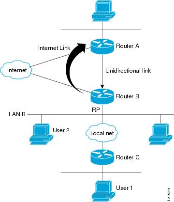
The IGMP Proxy mechanism enables hosts that are not directly connected to a downstream router to join a multicast group sourced from an upstream network. Figure 1 illustrates this mechanism.
Figure 1 IGMP Mroute Proxy Mechanism
In the scenario in Figure 1, the following sequence of events occurs:
1.
2.
3.
4.
5.
In an enterprise network, for example, it is desirable to be able to receive IP multicast traffic via satellite and forward the traffic throughout the network. With IGMP unidirectional link routing (UDLR) alone, this scenario is not possible because receiving hosts must be directly connected to the downstream router. IGMP Proxy overcomes this limitation by creating an IGMP report for (*, G) entries in the multicast forwarding table. To make this scenario functional, you must configure PIM sparse mode (PIM-SM) in the network, make the UDL downstream router the rendezvous point (RP) for a select set of addresses, and configure mroute proxy on interfaces leading to PIM-enabled networks with potential members. When the UDL downstream router has a (*, G) forwarding entry for an mroute proxy interface, an IGMP report for the group is created and sent to a loopback interface (IGMP Proxy interface). The loopback interface then uses the same mechanism as IGMP UDLR to forward reports upstream.
Note
Prerequisites
Before configuring IGMP Proxy, ensure that the following conditions exist:
•
•
SUMMARY STEPS
1.
2.
3.
4.
5.
6.
7.
8.
9.
DETAILED STEPS
Troubleshooting IGMP
Sometimes there is no group member on a network segment or a host cannot report its group membership using IGMP, yet you might want multicast traffic to go to that network segment. There are two ways to pull multicast traffic down to a network segment:
•
•
To troubleshoot IGMP, you can clear all the entries from the IGMP cache, and then the groups will be relearned by the router. You can ping a group to verify that the group exists and you can display information about the groups and multicast information related to an interface.
Use the appropriate step or steps in this task, depending on which situation above applies to your network.
SUMMARY STEPS
1.
2.
3.
4.
5.
6.
7.
8.
9.
10.
DETAILED STEPS
Configuration Examples for IGMP
This section contains the following configuration examples:
•
•
•
•
•
•
Customizing IGMP Router Functions: Example
In the following example, the query interval is set to 120 seconds and the timeout is set to 240 seconds:
access-list 1 permit 225.2.2.2interface ethernet 0ip igmp version 3ip igmp access-group 1!interface ethernet 1ip igmp join-group 225.2.2.2ip igmp query-interval 120ip igmp querier-timeout 240Configuring the IGMP State Limit: Example
In the following example, the number of IGMP membership reports on Ethernet interface 0 is limited to 100 reports and IGMP membership reports permitted by access list 199 do not count toward the configured state limit:
interface ethernet 0ip igmp limit 100 except 199The following sample output from the show ip igmp interface command illustrates the IGMP limit of 100 IGMP membership reports and no reports permitted by access list 199 count toward the limit:
Router# show ip igmp interfaceEthernet0 is up, line protocol is upInternet address is 192.168.37.6, subnet mask is 255.255.255.0IGMP is enabled on interfaceIGMP query interval is 60 secondsInbound IGMP access group is not setip igmp limit 100 except 199Multicast routing is enabled on interfaceMulticast TTL threshold is 0Multicast designated router (DR) is 192.168.37.33No multicast groups joinedEthernet1 is up, line protocol is upInternet address is 192.168.36.129, subnet mask is 255.255.255.0IGMP is enabled on interfaceIGMP query interval is 60 secondsInbound IGMP access group is not setip igmp limit 100 except 199Multicast routing is enabled on interfaceMulticast TTL threshold is 0Multicast designated router (DR) is 192.168.36.131Multicast groups joined: 225.2.2.2 226.2.2.2Tunnel0 is up, line protocol is upInternet address is 10.1.37.2, subnet mask is 255.255.0.0IGMP is enabled on interfaceIGMP query interval is 60 secondsInbound IGMP access group is not setip igmp limit 100 except 199Multicast routing is enabled on interfaceMulticast TTL threshold is 0No multicast groups joinedConfiguring IGMP v3: Example
The following example shows a basic configuration for enabling IP multicast with Source Specific Multicast (SSM), IGMPv3, and explicit tracking:
ip multicast routinginterface ethernet 0description access network to desktop systemsip address 10.1.0.1 255.255.255.0ip pim sparse-dense-modeip mroute-cacheip igmp version 3ip igmp explicit-trackingip igmp v3liteip urdinterface ethernet 1description backbone interface !No hosts connectedip address 10.10.0.1 255.255.255.0ip pim sparse-dense-modeip mroute-cacheip pim ssm defaultThe following is sample output from the show ip igmp membership user EXEC command. Each entry in the output shows the aggregate membership information (indicated by the A flag) for a particular multicast group or channel from the IGMP cache. If the entry is preceded by a forward slash (/) flag, the entry is a filtering entry that is blocking the data forwarding of the multicast group or channel.
Router> show ip igmp membershipFlags:A - aggregate, T - trackedL - Local, S - static, V - virtual, R - Reported through v3I - v3lite, D - Urd, M - SSM (S,G) channel1,2,3 - The version of IGMP, the group is inChannel/Group-Flags:/ - Filtering entry (Exclude mode (S,G), Include mode (*,G))Reporter:<ip-address> - last reporter if group is not explicitly tracked<n>/<m> - <n> reporter in include mode,<m> reporter in excludeChannel/Group Reporter Uptime Exp. Flags Interface*,224.0.1.40 10.10.0.1 00:01:34 02:41 2LA Et2/0*,239.1.1.1 2/0 00:00:10 stop 3AT Et2/0The following is sample output from the show ip igmp membership user EXEC command with the multicast group address 239.1.1.1 and the tracked keyword specified:
Router> show ip igmp membership 239.1.1.1 trackedFlags:A - aggregate, T - trackedL - Local, S - static, V - virtual, R - Reported through v3I - v3lite, D - Urd, M - SSM (S,G) channel1,2,3 - The version of IGMP, the group is inChannel/Group-Flags:/ - Filtering entry (Exclude mode (S,G), Include mode (*,G))Reporter:<ip-address> - last reporter if group is not explicitly tracked<n>/<m> - <n> reporter in include mode,<m> reporter in excludeChannel/Group Reporter Uptime Exp. Flags Interface*,239.1.1.1 2/0 00:00:11 stop 3AT Et2/010.30.0.100,239.1.1.1 10.10.0.10 00:00:11 02:48 RT Et2/010.30.0.101,239.1.1.1 10.10.0.20 00:00:03 02:56 RT Et2/010.30.0.101,239.1.1.1 10.10.0.10 00:00:11 02:48 RT Et2/010.30.0.102,239.1.1.1 10.10.0.20 00:00:03 02:56 RT Et2/0Controlling Access to an SSM Network: Examples
This subsection contains the following configuration examples for controlling access to an SSM network:
•
•
•
•
•
Note
Denying All States for a Group G: Example
The following example shows how to deny all states for a group G. In this example, FastEthernet interface 0/0 is configured to filter all sources for SSM group 232.2.2.2 in IGMPv3 reports, which effectively denies this group.
ip access-list extended test1deny igmp any host 232.2.2.2permit igmp any any!interface FastEthernet0/0ip igmp access-group test1Denying All States for a Source S: Example
The following example shows how to deny all states for a source S. In this example, Ethernet interface 1/1 is configured to filter all groups for source 10.2.1.32 in IGMPv3 reports, which effectively denies this source.
ip access-list extended test2deny igmp host 10.2.1.32 anypermit igmp any any!interface Ethernet1/1ip igmp access-group test2Permitting All States for a Group G: Example
The following example shows how to permit all states for a group G. In this example, Ethernet interface 1/2 is configured to accept all sources for SSM group 232.1.1.10 in IGMPv3 reports, which effectively accepts this group altogether.
ip access-list extended test3permit igmp any host 232.1.1.10!interface Ethernet1/2ip igmp access-group test3Permitting All States for a Source S: Example
The following example shows how to permit all states for a source S. In this example, Ethernet interface 1/2 is configured to accept all groups for source 10.6.23.32 in IGMPv3 reports, which effectively accepts this source altogether.
ip access-list extended test4permit igmp host 10.6.23.32 any!interface Ethernet1/2ip igmp access-group test4Filtering a Source S for a Group G: Example
The following example shows how to filter a particular source S for a group G. In this example, Ethernet interface 0/3 is configured to filter source 232.2.2.2 for SSM group 232.2.30.30 in IGMPv3 reports.
ip access-list extended test5deny igmp host 10.4.4.4 host 232.2.30.30permit igmp any any!interface Ethernet0/3ip igmp access-group test5Configuring an IGMP Intermediate Helper: Example
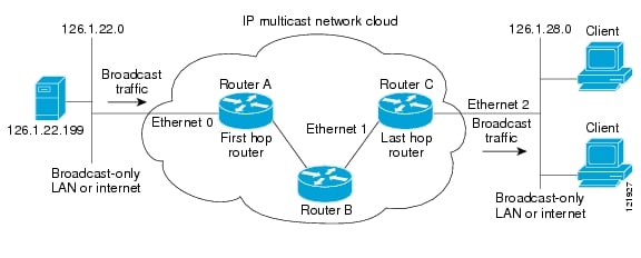
Figure 2 illustrates how a helper address on two routers converts traffic from broadcast to multicast and back to broadcast.
Figure 2 IP Multicast Helper
In this example, a server on the LAN connected to Ethernet interface 0 of Router A is sending a UDP broadcast stream with a source address of 126.1.22.199 and a destination address of 126.1.22.255:4000. The configuration on the first hop router converts the broadcast stream arriving at incoming Ethernet interface 0 destined for UDP port 4000 to a multicast stream. The access list permits traffic being sent from the server at 126.1.22.199 being sent to 126.1.22.255:4000. The traffic is sent to group address 239.254.2.5. The ip forward-protocol command specifies the forwarding of broadcast messages destined for UDP port 4000.
Note
The second configuration on the last hop router converts the multicast stream arriving at incoming Ethernet interface 1 back to broadcast at outgoing Ethernet interface 2. Again, not all multicast traffic emerging from the multicast cloud should be converted from multicast to broadcast, only the traffic destined for 126.1.22.255:4000.
The configurations for Router A and Router C are as follows:
Router A—First Hop Router Configuration
interface ethernet 0ip address 126.1.22.1 255.255.255.0ip pim sparse-modeip multicast helper-map broadcast 239.254.2.5 105access-list 105 permit udp host 126.1.22.199 host 126.1.22.255 eq 4000ip forward-protocol udp 4000Router C—Last Hop Router Configuration
interface ethernet 1ip address 126.1.26.1 255.255.255.0ip pim sparse-modeip multicast helper-map 239.254.2.5 126.1.28.255 105interface ethernet 2ip address 126.1.28.1 255.255.255.0ip directed-broadcastaccess-list 105 permit udp host 126.1.22.199 any eq 4000ip forward-protocol udp 4000Configuring Stub IP Multicast Routing: Example
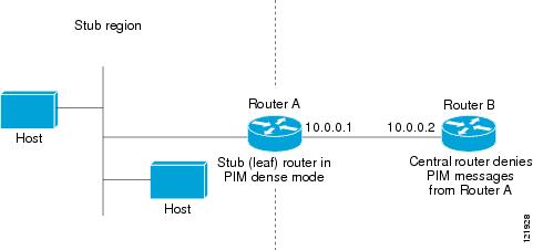
The following example shows how to configure stub IP multicast routing for Router A. Figure 3 illustrates the example. On stub Router A, the interfaces must be configured for PIM dense mode. The helper address is configured on the host interfaces. Central site Router B can be configured for either PIM sparse mode or dense mode. The access list on Router B denies any PIM messages from Router A.
Figure 3 Stub IP Multicast Routing
The configurations for Router A and Router B are as follows:
Router A Configuration
ip multicast-routingip pim dense-modeip igmp helper-address 10.0.0.2Router B Configuration
ip multicast-routingip pim dense-mode : or ip pim sparse-modeip pim neighbor-filter 1access-list 1 deny 10.0.0.1Configuring an IGMP Proxy: Example
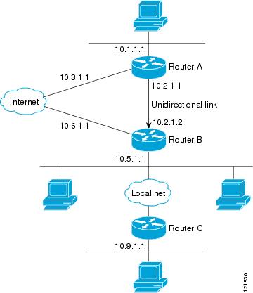
The following example shows how to configure an IGMP Proxy. In this example, Router C sends a PIM-SM Join message to Router B for multicast group G. Router B sends a request to Router A for an IGMP report for group G. Router A then forwards group G multicast traffic over the UDL. Figure 4 illustrates this example.
Figure 4 IGMP Mroute Proxy Topology
Router A Configuration
interface ethernet 0ip address 10.1.1.1 255.255.255.0ip pim dense-mode!interface ethernet 1ip address 10.2.1.1 255.255.255.0ip pim dense-modeip igmp unidirectional link!interface ethernet 2ip address 10.3.1.1 255.255.255.0Router B Configuration
ip pim rp-address 10.5.1.1 5access-list 5 permit 239.0.0.0 0.255.255.255.255!interface loopback 0ip address 10.7.1.1 255.255.255.0ip pim dense-modeip igmp helper-address udl ethernet 0ip igmp proxy-service!interface ethernet 0ip address 10.2.1.2 255.255.255.0ip pim dense-modeip igmp unidirectional link!interface ethernet 1ip address 10.5.1.1 255.255.255.0ip pim sparse-modeip igmp mroute-proxy loopback 0!interface ethernet 2ip address 10.6.1.1 255.255.255.0Router C Configuration
ip pim rp-address 10.5.1.1 5access-list 5 permit 239.0.0.0 0.255.255.255!interface ethernet 0ip address 10.8.1.1 255.255.255.0ip pim sparse-mode!interface ethernet 1ip address 10.9.1.1 255.255.255.0ip pim sparse-modeIGMP Proxy Verification: Example
To verify that IGMP Proxy is configured properly, use the show ip igmp udlr EXEC command. The following sample output shows that IGMP Proxy is configured on Ethernet interface 1/0/6.
Router# show ip igmp udlrIGMP UDLR Status, UDL Interfaces:Ethernet1/0/6Group Address Interface UDL Reporter Reporter Expires239.1.1.2 Ethernet1/0/6 10.10.0.3 00:02:59239.1.1.1 Ethernet1/0/6 10.10.0.2 00:02:40The following is sample output from the show ip igmp groups command:
Router# show ip igmp groupsIGMP Connected Group MembershipGroup Address Interface Uptime Expires Last Reporter239.255.255.254 Ethernet3/1 1w0d 00:02:19 172.21.200.159224.0.1.40 Ethernet3/1 1w0d 00:02:15 172.21.200.1224.0.1.40 Ethernet3/3 1w0d never 172.16.214.251224.0.1.1 Ethernet3/1 1w0d 00:02:11 172.21.200.11224.9.9.2 Ethernet3/1 1w0d 00:02:10 172.21.200.155232.1.1.1 Ethernet3/1 5d21h stopped 172.21.200.206The following is sample output from the show ip igmp groups command with the group-address argument and detail keyword:
Router# show ip igmp groups 232.1.1.1 detailInterface: Ethernet3/2Group: 232.1.1.1Uptime: 01:58:28Group mode: INCLUDELast reporter: 10.0.119.133CSR Grp Exp: 00:02:38Group source list: (C - Cisco Src Report, U - URD, R - Remote)Source Address Uptime v3 Exp CSR Exp Fwd Flags172.16.214.1 01:58:28 stopped 00:02:31 Yes CWhere to Go Next
•
•
•
•
•
•
•
•
•
To validate a multicast test packet, see the "Using the Multicast Routing Monitor" module.
Additional References
The following sections provide references related to customizing IGMP.
Related Documents
IP multicast concepts and tasks
•
•
IP multicast commands: complete command syntax, command mode, command history, defaults, usage guidelines, and examples
•
•
•
•
•
Standards
No new or modified standards are supported by these features, and support for existing standards has not been modified by these features.
—
MIBs
RFCs
RFC 1112
Host extensions for IP multicasting
RFC 2236
Internet Group Management Protocol, Version 2
Technical Assistance
Feature Information for Customizing IGMP
Table 2 lists the features in this module and provides links to specific configuration information. Only features that were introduced or modified in Cisco IOS Releases 12.2(1) or 12.0(3)S or a later release appear in the table.
For information on a feature in this technology that is not documented here, see the "IP Multicast Features Roadmap."
Not all commands may be available in your Cisco IOS software release. For release information about a specific command, see the command reference documentation.
Use Cisco Feature Navigator to find information about platform support and software image support. Cisco Feature Navigator enables you to determine which Cisco IOS and Catalyst OS software images support a specific software release, feature set, or platform. To access Cisco Feature Navigator, go to http://www.cisco.com/go/cfn. An account on Cisco.com is not required.
Note
Table 2 Feature Information for Customizing IGMP
Extended ACL Support for IGMP to Support SSM in IPv4
12.0(19)S
12.3(7)T
12.2(25)S
12.2(27)SBC
12.2(33)SRA
12.2(33)SXHThe Extended ACL Support for IGMP to Support SSM in IPv4 feature enables IGMPv3 to accomodate extended access lists. IGMPv3 support of extended access lists allows you to leverage an important advantage of SSM in IPv4, that of filtering IGMPv3 reports based on source address, group address, or both.
The following sections provide information about this feature:
•
•
The following command was introduced by this feature:
ip igmp access-group.IGMP State Limit
12.2(14)S
12.2(15)TThe IGMP State Limit feature limits the vulnerability of a router to DoS attacks with IGMP packets.
The following sections provide information about this feature:
•
•
The following commands were introduced or modified by this feature: ip igmp limit (global), ip igmp limit (interface), show ip igmp interface.
IGMPv3—Explicit Tracking Host, Group, and Channel
12.0(19)S
12.2(8)T
12.2(14)SThis IGMPv3—Explicit Tracking Host, Group, and Channel feature enables a multicast router to explicitly track the membership of all multicast hosts in a particular multiaccess network. This enhancement to the Cisco IOS implementation of IGMPv3 enables the router to track each individual host that is joined to a particular group or channel.
The following sections provide information about this feature:
•
The following commands were introduced by this feature:
ip igmp explicit-tracking, show ip igmp membership.
Any Internet Protocol (IP) addresses used in this document are not intended to be actual addresses. Any examples, command display output, and figures included in the document are shown for illustrative purposes only. Any use of actual IP addresses in illustrative content is unintentional and coincidental.
© 2005-2007 Cisco Systems, Inc. All rights reserved.