Feedback
Table Of Contents
Multichannel STM-1 Port Adapter
PA-MC-STM-1 Multiplexing Hierarchy
Related Features and Technologies
Supported Standards, MIBs, and RFCs
Configuring the SONET Controller
Configuring a Channel Group on an E1 of an AU-3
Configuring a Channel Group on an E1 of a TUG-3
Configuring an E1 Line Mapped to an AU-3
Configuring an E1 Line Mapped to a TUG-3
Monitoring and Maintaining the PA-MC-STM-1
Configuring the PA-MC-STM-1 Example
Configuring a Logical Channel Group on an E1 Line Example
Configuring a Channel Group Interface Example
Configuring an E1 Unframed Channel Example
Multichannel STM-1 Port Adapter
Feature History
This feature module describes the multichannel STM-1 port adapter (PA-MC-STM-1) in Cisco IOS Release 12.2(8)T and includes the following sections:
•
Supported Standards, MIBs, and RFCs
•
Feature Overview
The PA-MC-STM-1 is a high-speed, single-port multichannel STM-1 port adapter. You can configure the PA-MC-STM-1 as a multichannel E1/E0 STM-1 port. The PA-MC-STM-1 can be configured into 63 individual E1 links. Each E1 link can carry a single channel at full or fractional rates, or be broken down into multiple DS0 or nx64 Kbps rates. The PA-MC-STM-1 supports up to three TUG-3/AU-3 transport slots numbered 1 through 3. You can configure each TUG-3/AU-3 to carry 21 SDH TU-12s. Each SDH TU-12 is capable of carrying a channelized E1 frame, which can be unchannelized to nx64-Kbps time slots.
PA-MC-STM-1 Multiplexing Hierarchy
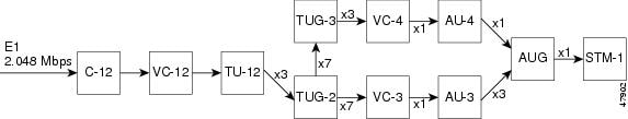
Figure 1 illustrates the synchronous digital hierarchy (SDH) multiplexing structure supported on the PA-MC-STM-1. The PA-MC-STM-1 multiplexing structure is a subset of that defined in ITU-T G.707. At the lowest level, containers (Cs) are input into virtual containers (VCs) with stuffing bits to create a uniform VC payload with a common bit-rate, ready for synchronous multiplexing. The VCs are then aligned into tributary units (TUs) where pointer processing operations are implemented. This allows the TUs to be multiplexed into TU groups (TUGs). Three TU-12s can be multiplexed into one TUG-2.
Figure 1 PA-STM-1 Multiplexing Structure
The TUGs are then multiplexed into higher-level VCs, which in turn are multiplexed into administrative units (AUs).The AUs are then multiplexed into an AU group (AUG), and the final payload from the AUG is then multiplexed into the Synchronous Transport Module (STM).
Benefits
The PA-MC-STM-1 port adapter provides the following benefits:
•
•
•
•
•
Restrictions
The PA-MC-STM-1 does not support the following:
•
•
•
•
•
Related Features and Technologies
•
•
Related Documents
•
•
•
•
Supported Platforms
•
•
Determining Platform Support Through Cisco Feature Navigator
Cisco IOS software is packaged in feature sets that support specific platforms. To get updated information regarding platform support for this feature, access Cisco Feature Navigator. Cisco Feature Navigator dynamically updates the list of supported platforms as new platform support is added for the feature.
Cisco Feature Navigator is a web-based tool that enables you to determine which Cisco IOS software images support a specific set of features and which features are supported in a specific Cisco IOS image. You can search by feature or release. Under the release section, you can compare releases side by side to display both the features unique to each software release and the features in common.
To access Cisco Feature Navigator, you must have an account on Cisco.com. If you have forgotten or lost your account information, send a blank e-mail to cco-locksmith@cisco.com. An automatic check will verify that your e-mail address is registered with Cisco.com. If the check is successful, account details with a new random password will be e-mailed to you. Qualified users can establish an account on Cisco.com by following the directions at http://www.cisco.com/register.
Cisco Feature Navigator is updated regularly when major Cisco IOS software releases and technology releases occur. For the most current information, go to the Cisco Feature Navigator home page at the following URL:
Availability of Cisco IOS Software Images
Platform support for particular Cisco IOS software releases is dependent on the availability of the software images for those platforms. Software images for some platforms may be deferred, delayed, or changed without prior notice. For updated information about platform support and availability of software images for each Cisco IOS software release, refer to the online release notes or, if supported, Cisco Feature Navigator.
Supported Standards, MIBs, and RFCs
Standards
•
•
•
•
•
•
•
•
•
•
MIBs
No new or modified MIBs are supported by this feature.
To obtain lists of supported MIBs by platform and Cisco IOS release, and to download MIB modules, go to the Cisco MIB website on Cisco.com at the following URL:
http://www.cisco.com/public/sw-center/netmgmt/cmtk/mibs.shtml
RFCs
•
•
Note
Prerequisites
The PA-MC-STM-1 requires a VIP4-80 installed in a Cisco 7500 series router.
Configuration Tasks
See the following sections for configuration tasks for the PA-MC-STM-1. Each task in the list indicates if the task is optional or required.
•
•
•
•
•
•
•
•
Configuring the SONET Controller
To configure the SONET controller, use the following commands beginning in privileged EXEC mode:
Configuring an AU-3
Each of the administrative unit group (AUGs) and tributary unit group (TUGs) of a PA-MC-STM-1 can be configured to carry a set of E1 links that are mapped into TU-12s. To configure the AUG mapping to AU-3, use the following commands beginning in global configuration mode:
Configuring a TUG-3
Each of the administrative unit groups (AUGs) and tributary unit groups (TUGs) of a PA-MC-STM-1 can be configured to carry a set of E1 links that are mapped into TU-12s. To configure the AUG mapping to AU-4, use the following commands beginning in global configuration mode:
Configuring a Channel Group on an E1 of an AU-3
To configure a channel group on an E1 of an AU-3, use the following commands beginning in global configuration mode:
Configuring a Channel Group on an E1 of a TUG-3
To configure a channel group on an E1 of a TUG-3, use the following commands beginning in global configuration mode:
Configuring an E1 Line Mapped to an AU-3
To configure an E1 line mapped to an AU-3, use the following commands beginning in global configuration mode:
Configuring an E1 Line Mapped to a TUG-3
To configure an E1 line mapped to a TUG-3, use the following commands beginning in global configuration mode:
Verifying the Configuration
You can verify the configuration and status of the controller by using the show controller commands as detailed below.
When AUG mapping is AU-4, view information about the SONET controller on a Cisco 7200 series router using the sonet controller sonet slot/port [brief | tabular] command. Use the sonet controller sonet slot/port-adapter/port [brief | tabular] command for a Cisco 7500 series router.
The following examples show sample output for a Cisco 7500 series router:
Router# show controller sonet 2/0/0SONET 2/0/0 is up.Channelized OC-3/STM-1 SMI PAH/W Version :0.2.3, ROM Version :1.2FREEDM version :2, F/W Version :1.2.0Applique type is Channelized Sonet/SDHClock Source is Internal, AUG mapping is AU4.Medium info:Type:SDH, Line Coding:NRZ, Line Type:Short SMRegenerator Section Status:No alarms detected.Multiplex Section Status:No alarms detected.Higher Order Path Status:Path# 1 has no defectsLower Order Path Status:VC-12 1/1/1/1 has no defectsVC-12 1/1/1/2 has no defectsVC-12 1/1/1/3 has no defectsVC-12 1/1/2/1 has no defectsVC-12 1/1/2/2 has no defectsVC-12 1/1/2/3 has no defects[display text omitted]Data in current interval (137 seconds elapsed):Regenerator Section:0 CVs, 0 ESs, 0 SESs, 0 SEFSsMultiplex Section:0 CVs, 0 ESs, 0 SESs, 0 UASsHigher Order Path:Path# 1: 0 CVs, 0 ESs, 0 SESs, 0 UASsLower Order Path:VC-12 1/1/1/1: 0 CVs, 0 ESs, 0 SESs, 0 UASsVC-12 1/1/1/2: 0 CVs, 0 ESs, 0 SESs, 0 UASsVC-12 1/1/1/3: 0 CVs, 0 ESs, 0 SESs, 0 UASsVC-12 1/1/2/1: 0 CVs, 0 ESs, 0 SESs, 0 UASs[display text omitted]SONET 2/0/0 E1 1/1/1/1 is upNo alarms detected.Framing is crc4, Clock Source is internal, National bits are 0x1F.Data in current interval (137 seconds elapsed):0 Line Code Violations, 0 Path Code Violations0 Slip Secs, 0 Fr Loss Secs, 0 Line Err Secs, 0 Degraded Mins0 Errored Secs, 0 Bursty Err Secs, 0 Severely Err Secs0 Unavail SecsSONET 2/0/0 E1 1/1/1/2 is upNo alarms detected.Framing is crc4, Clock Source is internal, National bits are 0x1F.Data in current interval (137 seconds elapsed):0 Line Code Violations, 0 Path Code Violations0 Slip Secs, 0 Fr Loss Secs, 0 Line Err Secs, 0 Degraded Mins0 Errored Secs, 0 Bursty Err Secs, 0 Severely Err Secs0 Unavail Secs[display text omitted]Router# show controller sonet 2/0/0 briefSONET 2/0/0 is up.Channelized OC-3/STM-1 SMI PAH/W Version :0.2.3, ROM Version :1.2FREEDM version :2, F/W Version :1.2.0Applique type is Channelized Sonet/SDHClock Source is Internal, AUG mapping is AU4.Medium info:Type:SDH, Line Coding:NRZ, Line Type:Short SMRegenerator Section Status:No alarms detected.Multiplex Section Status:No alarms detected.Higher Order Path Status:Path# 1 has no defectsLower Order Path Status:VC-12 1/1/1/1 has no defectsVC-12 1/1/1/2 has no defectsVC-12 1/1/1/3 has no defectsVC-12 1/1/2/1 has no defectsVC-12 1/1/2/2 has no defectsVC-12 1/1/2/3 has no defects[display text omitted]SONET 2/0/0 E1 1/1/1/1 is upNo alarms detected.Framing is crc4, Clock Source is internal, National bits are 0x1F.SONET 2/0/0 E1 1/1/1/2 is upNo alarms detected.Framing is crc4, Clock Source is internal, National bits are 0x1F.SONET 2/0/0 E1 1/1/1/3 is upNo alarms detected.Framing is crc4, Clock Source is internal, National bits are 0x1F.[display text omitted]Router# show controller sonet 2/0/0 tabularSONET 2/0/0 is up.Channelized OC-3/STM-1 SMI PAH/W Version :0.2.3, ROM Version :1.2FREEDM version :2, F/W Version :1.2.0Applique type is Channelized Sonet/SDHClock Source is Internal, AUG mapping is AU4.Medium info:Type:SDH, Line Coding:NRZ, Line Type:Short SMRegenerator Section Status:No alarms detected.Multiplex Section Status:No alarms detected.Higher Order Path Status:Path# 1 has no defectsLower Order Path Status:VC-12 1/1/1/1 has no defectsVC-12 1/1/1/2 has no defectsVC-12 1/1/1/3 has no defectsVC-12 1/1/2/1 has no defects[display text omitted]Regenerator Section:INTERVAL CV ES SES SEFS20:47-20:50 0 0 0 0Multiplex Section:INTERVAL CV ES SES UAS20:47-20:50 0 0 0 0Higher Order Path:Path# 1:INTERVAL CV ES SES UAS20:47-20:50 0 0 0 0Lower Order Path:AU-4# 1, TUG-3# 1, TUG-2# 1 VC-12# 1:INTERVAL CV ES SES UAS20:47-20:50 0 0 0 0AU-4# 1, TUG-3# 1, TUG-2# 1 VC-12# 2:INTERVAL CV ES SES UAS20:47-20:50 0 0 0 0AU-4# 1, TUG-3# 1, TUG-2# 1 VC-12# 3:INTERVAL CV ES SES UAS20:47-20:50 0 0 0 0[display text omitted]SONET 2/0/0 E1 1/1/1/1 is upNo alarms detected.Framing is crc4, Clock Source is internal, National bits are 0x1F.INTERVAL LCV PCV CSS SEFS LES DM ES BES SES UAS SS20:47-20:50 0 0 0 0 0 0 0 0 0 0 0SONET 2/0/0 E1 1/1/1/2 is upNo alarms detected.Framing is crc4, Clock Source is internal, National bits are 0x1F.INTERVAL LCV PCV CSS SEFS LES DM ES BES SES UAS SS20:47-20:50 0 0 0 0 0 0 0 0 0 0 0SONET 2/0/0 E1 1/1/1/3 is upNo alarms detected.Framing is crc4, Clock Source is internal, National bits are 0x1F.INTERVAL LCV PCV CSS SEFS LES DM ES BES SES UAS SS20:46-20:50 0 1 0 0 0 0 0 0 0 32 0[display text omitted]When AUG mapping is AU-3, view information about the SONET controller by using the sonet controller sonet slot/port [brief | tabular] command for a Cisco 7200 series router. Use the sonet controller sonet slot/port-adapter/port [brief | tabular] command for a Cisco 7500 series router.
The following examples show sample output for a Cisco 7500 series router:
Router# show controller sonet 2/0/0SONET 2/0/0 is up.Channelized OC-3/STM-1 SMI PAH/W Version :0.2.3, ROM Version :1.2FREEDM version :2, F/W Version :1.2.0Applique type is Channelized Sonet/SDHClock Source is Internal, AUG mapping is AU3.Medium info:Type:SDH, Line Coding:NRZ, Line Type:Short SMRegenerator Section Status:No alarms detected.Multiplex Section Status:No alarms detected.Higher Order Path Status:Path# 1 has no defectsPath# 2 has no defectsPath# 3 has no defectsLower Order Path Status:VC-12 1/1/1 has no defectsVC-12 1/1/2 has no defectsVC-12 1/1/3 has no defectsVC-12 1/2/1 has no defects[display text omitted]Data in current interval (85 seconds elapsed):Regenerator Section:0 CVs, 0 ESs, 0 SESs, 0 SEFSsMultiplex Section:0 CVs, 0 ESs, 0 SESs, 0 UASsHigher Order Path:Path# 1: 0 CVs, 0 ESs, 0 SESs, 0 UASsPath# 2: 0 CVs, 0 ESs, 0 SESs, 0 UASsPath# 3: 0 CVs, 0 ESs, 0 SESs, 0 UASsLower Order Path:VC-12 1/1/1: 0 CVs, 0 ESs, 0 SESs, 0 UASsVC-12 1/1/2: 0 CVs, 0 ESs, 0 SESs, 0 UASsVC-12 1/1/3: 0 CVs, 0 ESs, 0 SESs, 0 UASsVC-12 1/2/1: 0 CVs, 0 ESs, 0 SESs, 0 UASsVC-12 1/2/2: 0 CVs, 0 ESs, 0 SESs, 0 UASs[display text omitted]SONET 2/0/0 E1 1/1/1 is upNo alarms detected.Framing is crc4, Clock Source is internal, National bits are 0x1F.Data in current interval (85 seconds elapsed):0 Line Code Violations, 0 Path Code Violations0 Slip Secs, 0 Fr Loss Secs, 0 Line Err Secs, 0 Degraded Mins0 Errored Secs, 0 Bursty Err Secs, 0 Severely Err Secs0 Unavail SecsSONET 2/0/0 E1 1/1/2 is upNo alarms detected.Framing is crc4, Clock Source is internal, National bits are 0x1F.Data in current interval (85 seconds elapsed):0 Line Code Violations, 0 Path Code Violations0 Slip Secs, 0 Fr Loss Secs, 0 Line Err Secs, 0 Degraded Mins0 Errored Secs, 0 Bursty Err Secs, 0 Severely Err Secs0 Unavail Secs[display text omitted]Router# show controller sonet 2/0/0 briefSONET 2/0/0 is up.Channelized OC-3/STM-1 SMI PAH/W Version :0.2.3, ROM Version :1.2FREEDM version :2, F/W Version :1.2.0Applique type is Channelized Sonet/SDHClock Source is Internal, AUG mapping is AU3.Medium info:Type:SDH, Line Coding:NRZ, Line Type:Short SMRegenerator Section Status:No alarms detected.Multiplex Section Status:No alarms detected.Higher Order Path Status:Path# 1 has no defectsPath# 2 has no defectsPath# 3 has no defectsLower Order Path Status:VC-12 1/1/1 has no defectsVC-12 1/1/2 has no defectsVC-12 1/1/3 has no defectsVC-12 1/2/1 has no defects[display text omitted]SONET 2/0/0 E1 1/1/1 is upNo alarms detected.Framing is crc4, Clock Source is internal, National bits are 0x1F.SONET 2/0/0 E1 1/1/2 is upNo alarms detected.Framing is crc4, Clock Source is internal, National bits are 0x1F.SONET 2/0/0 E1 1/1/3 is upNo alarms detected.Framing is crc4, Clock Source is internal, National bits are 0x1F.[display text omitted]Router# show controller sonet 2/0/0 tabularSONET 2/0/0 is up.Channelized OC-3/STM-1 SMI PAH/W Version :0.2.3, ROM Version :1.2FREEDM version :2, F/W Version :1.2.0Applique type is Channelized Sonet/SDHClock Source is Internal, AUG mapping is AU3.Medium info:Type:SDH, Line Coding:NRZ, Line Type:Short SMRegenerator Section Status:No alarms detected.Multiplex Section Status:No alarms detected.Higher Order Path Status:Path# 1 has no defectsPath# 2 has no defectsPath# 3 has no defectsLower Order Path Status:VC-12 1/1/1 has no defectsVC-12 1/1/2 has no defectsVC-12 1/1/3 has no defectsVC-12 1/2/1 has no defects[display text omitted]Regenerator Section:INTERVAL CV ES SES SEFS21:22-21:24 0 0 0 0Multiplex Section:INTERVAL CV ES SES UAS21:22-21:24 0 0 0 0Higher Order Path:Path# 1:INTERVAL CV ES SES UAS21:22-21:24 0 0 0 0Path# 2:INTERVAL CV ES SES UAS21:22-21:24 0 0 0 0Path# 3:INTERVAL CV ES SES UAS21:22-21:24 0 0 0 0Lower Order Path:AU-3# 1, TUG-2# 1 VC-12# 1:INTERVAL CV ES SES UAS21:22-21:24 0 0 0 0AU-3# 1, TUG-2# 1 VC-12# 2:INTERVAL CV ES SES UAS21:22-21:24 0 0 0 0AU-3# 1, TUG-2# 1 VC-12# 3:INTERVAL CV ES SES UAS21:22-21:24 0 0 0 0[display text omitted]SONET 2/0/0 E1 1/1/1 is upNo alarms detected.Framing is crc4, Clock Source is internal, National bits are 0x1F.INTERVAL LCV PCV CSS SEFS LES DM ES BES SES UAS SS21:22-21:24 0 0 0 0 0 0 0 0 0 0 0SONET 2/0/0 E1 1/1/2 is upNo alarms detected.Framing is crc4, Clock Source is internal, National bits are 0x1F.INTERVAL LCV PCV CSS SEFS LES DM ES BES SES UAS SS21:22-21:24 0 0 0 0 0 0 0 0 0 0 0SONET 2/0/0 E1 1/1/3 is upNo alarms detected.Framing is crc4, Clock Source is internal, National bits are 0x1F.INTERVAL LCV PCV CSS SEFS LES DM ES BES SES UAS SS21:22-21:24 0 0 0 0 0 0 0 0 0 0 0[display text omitted]When AUG mapping is AU-4, view information about a specific E1 line of a SONET controller by using the show controller sonet slot/port.au-4-number/tug-3-number/tug-2-number/e1-number [brief | tabular] command for a Cisco 7200 series router.
Use the show controller sonet slot/port-adapter/port.au-4-number/tug-3-number/tug-2-number/ e1-number [brief | tabular] command for a Cisco 7500 series router. This command displays error and performance statistics.
The following examples show sample output for a Cisco 7500 series router:
Router# show controller sonet 2/0/0.1/1/1/1SONET 2/0/0 is up.Channelized OC-3/STM-1 SMI PAH/W Version :0.2.3, ROM Version :1.2FREEDM version :2, F/W Version :1.2.0SONET 2/0/0 E1 1/1/1/1 is upNo alarms detected.Framing is crc4, Clock Source is internal, National bits are 0x1F.Data in current interval (237 seconds elapsed):0 Line Code Violations, 0 Path Code Violations0 Slip Secs, 0 Fr Loss Secs, 0 Line Err Secs, 0 Degraded Mins0 Errored Secs, 0 Bursty Err Secs, 0 Severely Err Secs0 Unavail SecsRouter# show controller sonet 2/0/0.1/1/1/1 briefSONET 2/0/0 is up.Channelized OC-3/STM-1 SMI PAH/W Version :0.2.3, ROM Version :1.2FREEDM version :2, F/W Version :1.2.0SONET 2/0/0 E1 1/1/1/1 is upNo alarms detected.Framing is crc4, Clock Source is internal, National bits are 0x1F.Router# show controller sonet 2/0/0.1/1/1/1 tabularSONET 2/0/0 is up.Channelized OC-3/STM-1 SMI PAH/W Version :0.2.3, ROM Version :1.2FREEDM version :2, F/W Version :1.2.0SONET 2/0/0 E1 1/1/1/1 is upNo alarms detected.Framing is crc4, Clock Source is internal, National bits are 0x1F.INTERVAL LCV PCV CSS SEFS LES DM ES BES SES UAS SS20:47-20:51 0 0 0 0 0 0 0 0 0 0 0Router# show controller sonet 0/0/0.1/2/4/1 briefSONET 0/0/0 is up.Channelized OC-3/STM-1 SMI PAH/W Version : 0.2.3, ROM Version : 1.2FREEDM version : 2, F/W Version : 0.14.0SONET 0/0/0 E1 1/2/4/1 is upNo alarms detected.Framing is crc4, Clock Source is line, National bits are 0x1F.Router# show controller sonet 0/0/0.1/2/4/1 tabularSONET 0/0/0 is up.Channelized OC-3/STM-1 SMI PAH/W Version : 0.2.3, ROM Version : 1.2FREEDM version : 2, F/W Version : 0.14.0SONET 0/0/0 E1 1/2/4/1 is upNo alarms detected.Framing is crc4, Clock Source is line, National bits are 0x1F.INTERVAL LCV PCV CSS SEFS LES DM ES BES SES UAS SS16:56-16:57 0 0 0 0 0 0 0 0 0 1 0When AUG mapping is AU-3, view information about a specific E1 line of a SONET controller by using the show controller sonet slot/port.au-3-number/tug-2-number/e1-number [brief | tabular] command for a Cisco 7200 series router.
Use the show controller sonet slot/port-adapter/port.au-3-number/tug-2-number/e1-number [brief | tabular] command for a Cisco 7500 series router. This command displays error and performance statistics.
The following examples show sample output for a Cisco 7500 series router:
Router# show controller sonet 2/0/0.1/1/1SONET 2/0/0 is up.Channelized OC-3/STM-1 SMI PAH/W Version :0.2.3, ROM Version :1.2FREEDM version :2, F/W Version :1.2.0SONET 2/0/0 E1 1/1/1 is upNo alarms detected.Framing is crc4, Clock Source is internal, National bits are 0x1F.Data in current interval (175 seconds elapsed):0 Line Code Violations, 0 Path Code Violations0 Slip Secs, 0 Fr Loss Secs, 0 Line Err Secs, 0 Degraded Mins0 Errored Secs, 0 Bursty Err Secs, 0 Severely Err Secs0 Unavail SecsRouter# show controller sonet 2/0/0.1/1/1 briefSONET 2/0/0 is up.Channelized OC-3/STM-1 SMI PAH/W Version :0.2.3, ROM Version :1.2FREEDM version :2, F/W Version :1.2.0SONET 2/0/0 E1 1/1/1 is upNo alarms detected.Framing is crc4, Clock Source is internal, National bits are 0x1F.Router# show controller sonet 2/0/0.1/1/1 briefSONET 2/0/0 is up.Channelized OC-3/STM-1 SMI PAH/W Version : 0.2.3, ROM Version : 1.2FREEDM version : 2, F/W Version : 0.14.0SONET 2/0/0 E1 1/1/1 is downTransmitter is sending LOF Indication (RAI).Receiver has loss of frame.Framing is crc4, Clock Source is internal, National bits are 0x1F.Router# show controller sonet 2/0/0.1/1/1 tabularSONET 2/0/0 is up.Channelized OC-3/STM-1 SMI PAH/W Version : 0.2.3, ROM Version : 1.2FREEDM version : 2, F/W Version : 0.14.0SONET 2/0/0 E1 1/1/1 is downTransmitter is sending LOF Indication (RAI).Receiver has loss of frame.Framing is crc4, Clock Source is internal, National bits are 0x1F.INTERVAL LCV PCV CSS SEFS LES DM ES BES SES UAS SS17:26-17:29 0 0 0 0 0 0 0 0 0 173 017:11-17:26 0 0 0 0 0 0 0 0 0 471 016:56-17:11 0 0 0 0 0 0 0 0 0 0 016:41-16:56 0 0 0 0 0 0 0 0 0 0 016:26-16:41 0 0 0 0 0 0 0 0 0 216 016:11-16:26 0 0 0 0 0 0 0 0 0 225 0Total 0 0 0 0 0 0 0 0 0 912 0Monitoring and Maintaining the PA-MC-STM-1
To monitor and maintain the PA-MC-STM-1, use the show interface command.
The following sample output displays the interface statistics of a PA-MC-STM-1 in port adapter slot 0 of a VIP4 in interface processor slot 2 of a Cisco 7500 series router:
Router# show interface serial 2/0/0.1.1.1.1:1
Serial2/0/0.1/1/1/1:1 is up, line protocol is up
Hardware is cyBus Channelized OC3/STM-1 PA
Internet address is 105.105.105.1/24
MTU 1500 bytes, BW 1984 Kbit, DLY 20000 usec, rely 255/255, load 36/255
Encapsulation HDLC, loopback not set
Keepalive not set
Last input 00:00:00, output 00:00:00, output hang never
Last clearing of "show interface" counters never
Input queue: 1/75/0 (size/max/drops); Total output drops: 0
Queueing strategy: weighted fair
Output queue: 0/1000/64/0 (size/max total/threshold/drops)
Conversations 0/1/256 (active/max active/max total)
Reserved Conversations 0/0 (allocated/max allocated)
5 minute input rate 286000 bits/sec, 36 packets/sec
5 minute output rate 284000 bits/sec, 36 packets/sec
8019 packets input, 11695347 bytes, 0 no buffer
Received 0 broadcasts, 0 runts, 0 giants, 0 throttles
0 input errors, 0 CRC, 0 frame, 0 overrun, 0 ignored, 0 abort
7991 packets output, 11650799 bytes, 0 underruns
0 output errors, 0 collisions, 0 interface resets
0 output buffer failures, 0 output buffers swapped out
2 carrier transitions no alarm present
Timeslot(s) Used:1-31, Transmitter delay is 0 flags, transmit queue length 6
[Additional display text for remaining interfaces omitted]
Configuration Examples
This section provides the following configuration examples:
•
•
•
•
Configuring the PA-MC-STM-1 Example
You can configure each of the AUGs and TUGs of a PA-MC-STM-1 to carry a set of E1 links that are mapped into tributary unit level-12s (TU-12s).
In the following example, SDH framing, internal clock source, AUG mapping au-4 and idle pattern are configured:
Router(config)# controller sonet 1/0Router(config-controller)# framing sdhRouter(config-controller)# clock source internalRouter(config-controller)# aug mapping au-4Router(config-controller)# au-4 1 tug-3 2Router(config-ctrlr-tug3)# mode c-12Router(config-ctrlr-tug3)# tug-2 4 e1 channel-group 15 timeslots 1-5, 20-23Router(config-ctrlr-tug3)# idle pattern 0x0Configuring a Logical Channel Group on an E1 Line Example
To configure a logical channel group on an E1 line, use the tug-2 tug-2-number e1 e1-number channel-group channel-group-number timeslots list-of-timeslots command. In the following example, logical channel group 15 on E1 line 1 is configured and channelized time slots 1 to 5 and 20 to 23 are assigned to the newly created logical channel group:
Router(config)# controller sonet 1/0/0Router(config-controller)# framing sdhRouter(config-controller)# aug mapping au-4Router(config-controller)# au-4 1 tug-3 2Router(config-ctrlr-tug3)# mode c-12Router(config-ctrlr-tug3)# tug-2 4 e1 1 channel-group 15 timeslots 1-5, 20-23Configuring a Channel Group Interface Example
Once a channel group has been created, interface serial configuration commands may be used as in the following example:
Router(config)# controller sonet 1/0/0Router(config-controller)# framing sdhRouter(config-controller)# aug mapping au-4Router(config-controller)# au-4 1 tug-3 2Router(config-ctrlr-tug3)# mode c-12Router(config-ctrlr-tug3)# tug-2 4 e1 10 channel-group 15 timeslots 1-5, 20-23Router(config-ctrlr-tug3)# exitRouter(config-controller)# exitRouter(config)# interface serial 1/1/0.1/2/4/1:15Router(config-if)# ip address 1.1.1.10 255.255.255.252Router(config-if)# encapsulation pppConfiguring an E1 Unframed Channel Example
To create an unframed or clear channel logical channel group on an E1 line, use the tug-2 tug-2-number e1 e1-number unframed command, as shown in the following example:
Router(config)# controller sonet 1/0/0Router(config-controller)# aug mapping au-4Router(config-controller)# au-4 1 tug-3 2Router(config-ctrlr-tug3)# tug-2 4 e1 1 unframedRouter(config-ctrlr-tug3)# mode c-12Command Reference
The following modified commands are pertinent to this feature. To see the command pages for these commands and other commands used with this feature, go to the Cisco IOS Master Commands List, Release 12.4, at http://www.cisco.com/univercd/cc/td/doc/product/software/ios124/124mindx/
124index.htm.•
•
•
•
•
•
•
•
•
•
•
•
•
Glossary
AUG—administrative unit group in SDH mode
BER—bit error rate
CAS—channel-associated signalling
CRC4—cyclic redundancy check. Error-checking technique in which the frame recipient calculates a remainder by dividing frame contents by a prime binary divisor and compares the calculated remainder to a value stored in the frame by the sending node.
E1—A digital carrier used to transmit a formatted signal at 2.048 Mbps.
ITU—International Telecommunication Union-Telecommunication standards sector
PRI—Primary Rate Interface
SDH—synchronous digital hierarchy. The ITU equivalent of SONET.
SONET—Synchronous Optical Network. The ANSI specification describing the data format used in high-speed optical data transmission
STM-n—Synchronous Transport Module level-n (STM-1 is 155.52 Mbps.)
TU-n—tributary unit level-n
TUG-n—tributary unit group-n
VC—virtual circuit
VC-n—virtual container level-n
VIP—Virtual Interface Processor
© 2005 Cisco Systems, Inc. All rights reserved.