Feedback
Table Of Contents
ATM Mode for Two-Wire or Four-Wire SHDSL
Prerequisites for ATM Mode for Two-Wire or Four-Wire SHDSL
Restrictions for ATM Mode for Two-Wire or Four-Wire SHDSL
Information About ATM Mode for Two-Wire or Four-Wire SHDSL
Interface and Controller Numbering on the Cisco 1721 Router
Interface Numbering on Cisco 2800 and Cisco 3800 Series Routers
How to Configure ATM Mode for Two-Wire or Four-Wire SHDSL
Verifying the ATM Configuration
Configuration Examples for ATM Mode for Two-Wire or Four-Wire SHDSL
Router A: CPE Configuration Example
Router B: CO Configuration Example
ATM Mode for Two-Wire or Four-Wire SHDSL
This document describes the ATM Mode for Two-Wire or Four-Wire SHDSL feature on the Cisco 1700 series, Cisco 1800 series, Cisco 2600 series, Cisco 2800, Cisco 3631, Cisco 3700, and Cisco 3800 series routers.
The ATM Mode for Two-Wire or Four-Wire SHDSL feature adds four-wire support in fixed line-rate mode only on a WIC-1SHDSL-V2. Two-wire mode supports two-wire line-rate and auto line-rate. This feature builds on the existing features of the Multirate Symmetrical High-Speed Digital Subscriber Line (G.SHDSL) feature supported on the 1-port G.SHDSL WAN interface card (WIC-1SHDSL). The four-wire feature of G.991.2 doubles the bandwidth in ATM mode and increases usable distance over two pairs of wires.
The WIC-1SHDSL-V2 supports ATM on two-wire and four-wire line mode. Embedded Operation Channel (EOC) messages support for customer premise equipment (CPE) is provided for two-wire and four-wire modes.
Feature Specifications for the ATM Mode for SHDSL
12.3(4)XD
This feature (WIC-1SHDSL-V2) was introduced on the Cisco 2600 series and Cisco 3700 series routers to add four-wire support. Two-wire support was previously available in 1-Port G.SHDSL WAN Interface Card for Cisco 2600 Series and Cisco 3600 Series Routers, Release 12.2(8)T.
12.3(4)XG
This feature (WIC-1SHDSL-V2) was integrated into Cisco IOS Release 12.3(4)XG on the Cisco 1700 series routers.
12.3(7)T
This feature (WIC-1SHDSL-V2) was integrated into the Cisco IOS Release 12.3(7)T on the Cisco 2600 series, Cisco 3631, and Cisco 3700 series routers. Cisco 1700 series routers do not support the WIC-1SHDSL-V2 in this release.
12.3(4)XG1
Support for the auto line-mode feature was added.
12.3(11)T
Support for the following was added: additional annex parameters for Cisco 1700, Cisco 2600, Cisco 2800, Cisco 3631, Cisco 3700, and Cisco 3800 series routers; the HDSL2-SHDSL-LINE-MIB (RFC3276); and support for the ATM Mode for SHDSL feature was added for Cisco 2800 series, and Cisco 3800 series routers.
12.3(14)T
Support was added for Cisco 1800 series routers and the Cisco 2801 Integrated Services router.
Finding Support Information for Platforms and Cisco IOS Software Images
Use Cisco Feature Navigator to find information about platform support and Cisco IOS software image support. Access Cisco Feature Navigator at http://www.cisco.com/go/fn. You must have an account on Cisco.com. If you do not have an account or have forgotten your username or password, click Cancel at the login dialog box and follow the instructions that appear.
Contents
•
Prerequisites for ATM Mode for Two-Wire or Four-Wire SHDSL
•
•
•
•
Prerequisites for ATM Mode for Two-Wire or Four-Wire SHDSL
•
•
Restrictions for ATM Mode for Two-Wire or Four-Wire SHDSL
•
•
•
•
•
•
•
•
•
•
Information About ATM Mode for Two-Wire or Four-Wire SHDSL
This section provides information about the ATM Mode for SHDSL feature.
•
•
SHDSL Features
Supported SHDSL features are listed as follows:
•
–
–
–
–
ATM Features
The supported ATM features in this release:
•
•
•
•
•
•
Interface and Controller Numbering on the Cisco 1721 Router
If a WIC-1SHDSL-V2 is installed in a Cisco 1721 router, the interfaces and controllers are assigned numbers based on a numbering scheme that is different from the slot numbering scheme on other Cisco routers. This is because the Cisco 1721 router assigns only a slot number without also assigning a port number. Other Cisco routers typically use a slot and port number combination.
If the WIC-1SHDSL-V2 (the DSL controller) is installed in slot 0, the T1/E1 controllers and the ATM interfaces (ADSL/SHDSL) will be numbered relative to the DSL controller in slot 0. See Table 2 for examples of the slot numbering scheme on the Cisco 1721 router.
With an ATM or MFT T1/E1 card in slot 0, the WIC-1SHDSL-V2 in slot 1 will be numbered relative to the number of ports in slot 0.
If both slots are occupied by DSL controllers, the logical interfaces configured on each controller will have the same number as the slot occupied by the DSL controller. All logical interfaces on the WIC-1SHDSL-V2, such as serial interfaces created during the configuration of channel groups in T1/E1 mode, will have the same number as the DSL controller.
Interface Numbering on Cisco 2800 and Cisco 3800 Series Routers
This section describes the interface numbering scheme for Cisco 2800 and Cisco 3800 series routers If an interface card is installed in a Cisco 2800 series or Cisco 3800 series router, the interfaces must use a triple-number scheme to identify them. This triple-number assignment is different from the standard interface numbering scheme on other Cisco routers.
Table 3 shows the interface numbering for the onboard Fast Ethernet ports and the interface slots on Cisco 2800 and Cisco 3800 series routers.
How to Configure ATM Mode for Two-Wire or Four-Wire SHDSL
To configure the ATM Mode for Two-Wire or Four-Wire SHDSL feature, perform the following tasks:
•
•
•
•
Configuring G.SHDSL Service
This section details how to configure the ATM Mode for Two-Wire or Four-Wire SHDSL feature for G.SHDSL service.
To configure G.SHDSL service in ATM mode on a Cisco router containing a G.SHDSL WIC, complete the steps in the Summary Steps or the Detailed Steps, beginning in global configuration mode.
Prerequisites
The following list of prerequisites should be followed for this configuration:
•
•
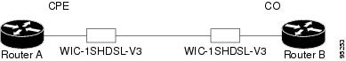
Figure 1 Back-to-Back Setup
SUMMARY STEPS
1.
2.
3.
4.
5.
6.
7.
8.
9.
10.
11.
12.
13.
14.
15.
16.
17.
18.
19.
20.
21.
22.
DETAILED STEPS
Examples
Example of the Configuration Before Configuring ATM Mode:
controller DSL 0/0line-term cpeExample for 4-wire ATM, Annex B, and Line Rate 3200
controller DSL 0/1mode atmline-term cpeline-mode 4-wiredsl-mode shdsl symmetric annex Bline-rate 3200What to Do Next
The next task is to verify the ATM mode or DSL mode for the router.
Verifying the ATM Configuration
Perform the steps in this section to verify the ATM Configuration.
SUMMARY STEPS
1.
2.
3.
4.
5.
6.
7.
8.
DETAILED STEPS
Examples
The following example shows how the show interface atm command is used and that the ATM slot/port and line protocol are up:
Router#show interfaces atm 0/0ATM0/0 is up, line protocol is upHardware is DSLSARMTU 4470 bytes, sub MTU 4470, BW 4608 Kbit, DLY 110 usec,reliability 0/255, txload 1/255, rxload 1/255Encapsulation ATM, loopback not setEncapsulation(s): AAL5 , PVC mode23 maximum active VCs, 256 VCs per VP, 1 current VCCsVC Auto Creation Disabled.VC idle disconnect time: 300 secondsLast input never, output never, output hang neverLast clearing of "show interface" counters neverInput queue: 0/75/0/0 (size/max/drops/flushes); Total output drops: 0Queueing strategy: Per VC Queueing30 second input rate 0 bits/sec, 0 packets/sec30 second output rate 0 bits/sec, 0 packets/sec0 packets input, 0 bytes, 0 no bufferReceived 0 broadcasts, 0 runts, 0 giants, 0 throttles0 input errors, 0 CRC, 0 frame, 0 overrun, 0 ignored, 0 abort0 packets output, 0 bytes, 0 underruns0 output errors, 0 collisions, 1 interface resets0 output buffer failures, 0 output buffers swapped out3725#show atm vcVCD / Peak Avg/MinBurstInterface Name VPI VCI Type Encaps SC Kbps KbpsCells Sts0/0.1 1 2 100 PVC MUX VBR 2000 2000 0 UP0/1.1 1 2 100 PVC SNAP CBR 4608 UP0/2.1 1 2 100 PVC SNAP VBR 4608 4200 0 UP1/0.1 1 2 100 PVC SNAP VBR 4608 4608 0 UP3725#Router# show atm vcVCD / Peak Avg/Min BurstInterface Name VPI VCI Type Encaps SC Kbps Kbps Cells Sts1/0.3 2 9 36 PVC MUX UBR 800 UP1/0.2 1 9 37 PVC SNAP UBR 800 UP3725#show controllers atm 0/0Interface: ATM0/0, Hardware: DSLSAR, State: upIDB: 645F4B98 Instance: 645F646C reg_dslsar:3C200000 wic_regs:3C200080PHY Inst:0 Ser0Inst: 645DFC8C Ser1Inst: 645EA608 us_bwidth:4608Slot: 0 Unit: 0 Subunit: 0 pkt Size: 4528VCperVP: 256 max_vp: 256 max_vc: 65536 total vc: 1rct_size:65536 vpivcibit:16 connTblVCI:8 vpi_bits: 8vpvc_sel:3 enabled: 0 throttled: 0 cell drops: 0Last Peridic Timer 00:44:26.872(2666872)Parallel reads to TCQ:0 tx count reset = 0, periodic safe start = 0Attempts to overwrite SCC txring: 0Host Controller lockup recovery Info:recovery count1= 0, recovery count2= 0Saved Host Controller Info to check any lockup:scc = 0, output_qcount = 0, head:0,buf addr = 0x00000000, serial outputs = 0scc = 1, output_qcount = 0, head:54,buf addr = 0x00000000, serial outputs = 212Serial idb(AAL5) output_qcount:0 max:40Serial idb(RAW) output_qcount:0, max:40Sar ctrl queue: max depth = 0, current queue depth = 0, drops = 0, uruncnt = 0, total cnt = 106Serial idb tx count: AAL5: 0, RAW: 212, Drop count:AAL5: 0, RAW: 0Host Controller Clock rate Info:SCC Clockrates:SCC0 = 1000000 (ATM0/0)SCC1 = 8000000 (ATM0/0)SCC2 = 1000000 (ATM0/1)SCC3 = 1000000 (ATM0/2)SCC4 = 5300000 (ATM0/1)SCC5 = 8000000 (ATM0/2)SCC6 = 0SCC7 = 0WIC Register Value Notes--------------- ---------- ----------FPGA Dev ID (LB) 0x53 'S'FPGA Dev ID (UB) 0x4E 'N'FPGA Revision 0xA7WIC Config Reg 0x35 WIC / VIC select = WIC;CTRLE addr bit 8 = 0;NTR Enable = 0;OK LED on;LOOPBACK LED off;CD LED on;WIC Config Reg2 0x07 Gen bus error on bad G.SHDSL ATM/T1/E1 accessInt 0 Enable Reg 0x01 G.SHDSL ATM/T1/E1 normal interrupt enabledG.SHDSL ATM/T1/E1 error interrupt disabledDSLSAR Register Value Notes--------------- ---------- ----------sdram_refresh: 0x410FFFF Expected value: 0x428xxxxintr_event_reg: 0xC0 TMR.intr_enable_reg: 0x13C FIFOF.FBQE.RQAF.RPQAF.TSQAF.config: 0x660D0A20 UTOPIA.RXEN.RegulateXmit.RMCell.TXEN.Rx Buffer size: 8192. RCT: Large, VPI Bits:8.status: 0x0clkPerCell: 814121 (line rate: 4608 Kbps)Pre-timer Count: 461rcid_tableBase: 0x0rct_base: 0x10000tstBase1: 0x13C28 TST boot jump.rawCellBase: 0x14300 (0/128) slots used.rpq_base: 0x16000tsqb(Tx Stat Q): 0x17000fbq_base: 0x17880 (fbq_count: 128)txChanQueue: 0x18000rxBuffers: 0x30000txBuffers: 0x130000Lookup Error cnt: 0x0Invalid Cell cnt: 0x0SCCA Rx Errors: 0x0SCCB Rx Errors: 0x0Drop Pkt Count: 0x0Total Tx Count: 0x0Total Rx Count: 0x0Timer: 0x73A141DSLSAR Interrupts:0x0Last Addr:0x12E14Router# show controllers atm 1/0Interface ATM1/0 is upHardware is DSLSAR (with Globespan G.SHDSL Module)IDB: 62586758 Instance:6258E054 reg_dslsar:3C810000 wic_regs:3C810080PHY Inst:62588490 Ser0Inst:62573074 Ser1Inst: 6257CBD8 us_bwidth:800Slot: 1 Unit: 1 Subunit: 0 pkt Size:4496VCperVP:256 max_vp: 256 max_vc: 65536 total vc:2rct_size:65536 vpivcibit:16 connTblVCI:8 vpi_bits:8vpvc_sel:3 enabled: 0 throttled:0WIC Register Value Notes--------------- ---------- ----------WIC Config Reg 0x45 WIC / VIC select = WIC;CTRLE addr bit 8 = 1;OK LED on;LOOPBACK LED off;CD LED on;WIC Config Reg2 0x07 Gen bus error on bad ADSL accessInt 0 Enable Reg 0x03 ADSL normal interrupt enabledADSL error interrupt enabledWhat to Do Next
Verify the configuration using the detailed steps in the "Verifying DSL Configuration" section.
Verifying DSL Configuration
Perform the steps in this section to verify the DSL Configuration.
SUMMARY STEPS
1.
2.
3.
4.
5.
6.
7.
DETAILED STEPS
Examples
The following example shows how to verify four-wire ATM mode in line zero (CPE):
Router#show controller dsl 0/0DSL 0/0 controller UPSLOT 0: Globespan xDSL controller chipsetDSL mode: SHDSL Annex BFrame mode: UtopiaConfigured Line rate: 4608KbpsLine Re-activated 4 times after system bootupLOSW Defect alarm: ACTIVECRC per second alarm: ACTIVELine termination: CPEFPGA Revision: 0xA7Line 0 statisticsCurrent 15 min CRC: 2116Current 15 min LOSW Defect: 8Current 15 min ES: 16Current 15 min SES: 15Current 15 min UAS: 112Previous 15 min CRC: 0Previous 15 min LOSW Defect: 0Previous 15 min ES: 0Previous 15 min SES: 0Previous 15 min UAS: 0Line 1 statisticsCurrent 15 min CRC: 450Current 15 min LOSW Defect: 0Current 15 min ES: 6Current 15 min SES: 5Current 15 min UAS: 61Previous 15 min CRC: 0Previous 15 min LOSW Defect: 0Previous 15 min ES: 0Previous 15 min SES: 0Previous 15 min UAS: 0Line-0 statusChipset Version: 1Firmware Version: A29733Modem Status: Data, Status 1Last Fail Mode: No Failure status:0x0Line rate: 2312 KbpsFramer Sync Status: In SyncRcv Clock Status: In the RangeLoop Attenuation: 0.600 dBTransmit Power: 8.5 dBReceiver Gain: 19.5420 dBSNR Sampling: 37.9860 dBLine-1 statusChipset Version: 1Firmware Version: A29733Modem Status: Data, Status 1Last Fail Mode: No Failure status:0x0Line rate: 2312 KbpsFramer Sync Status: In SyncRcv Clock Status: In the RangeLoop Attenuation: 0.4294966516 dBTransmit Power: 8.5 dBReceiver Gain: 19.5420 dBSNR Sampling: 37.6080 dBDying Gasp: PresentSample Output—Building Configuration
Router>show running-configCurrent configuration : 3183 bytes!version 12.3service timestamps debug uptimeservice timestamps log uptimeno service password-encryption!hostname 3725!boot-start-markerboot system flash c3725-is-mz.0424boot system tftp shriv/c3725-is-mz.new 223.255.254.254boot-end-marker!!memory-size iomem 25no network-clock-participate slot 1no network-clock-participate slot 2no network-clock-participate wic 0no network-clock-participate wic 1no network-clock-participate wic 2no network-clock-participate aim 0no network-clock-participate aim 1no aaa new-modelip subnet-zeroip cef!!!!!!!controller DSL 0/0mode atmline-term coline-mode 4-wiredsl-mode shdsl symmetric annex Bline-rate 4608!controller DSL 0/1mode atmline-term coline-mode 4-wiredsl-mode shdsl symmetric annex Bline-rate 4608controller DSL 0/2mode atmline-term coline-mode 4-wiredsl-mode shdsl symmetric annex Bline-rate 4608!controller DSL 1/0mode atmline-term coline-mode 4-wiredsl-mode shdsl symmetric annex Bline-rate 4608!!!interface ATM0/0no ip addressload-interval 30no atm ilmi-keepaliveclock rate aal5 8000000!interface ATM0/0.1 point-to-pointip address 5.0.0.1 255.0.0.0pvc 2/100vbr-rt 2000 2000oam-pvc 0encapsulation aal5mux ip!!interface FastEthernet0/0ip address 1.3.208.25 255.255.0.0duplex autospeed autono cdp enable!interface ATM0/1no ip addressload-interval 30no atm ilmi-keepaliveclock rate aal5 5300000!interface ATM0/1.1 point-to-pointip address 6.0.0.1 255.0.0.0pvc 2/100cbr 4608!!interface FastEthernet0/1mac-address 0000.0000.0011ip address 70.0.0.2 255.0.0.0 secondaryip address 90.0.0.2 255.0.0.0 secondaryip address 50.0.0.2 255.0.0.0load-interval 30speed 100full-duplexno cdp enable!interface ATM0/2no ip addressno atm ilmi-keepaliveclock rate aal5 8000000!interface ATM0/2.1 point-to-pointip address 7.0.0.1 255.0.0.0pvc 2/100vbr-nrt 4608 4200!!interface ATM1/0no ip addressload-interval 30no atm ilmi-keepaliveclock rate aal5 5300000!interface ATM1/0.1 point-to-pointip address 8.0.0.1 255.0.0.0pvc 2/100vbr-nrt 4608 4608!!interface FastEthernet1/0no ip addressshutdownduplex autospeed autono cdp enable!interface FastEthernet1/1no ip addressshutdownduplex autospeed autono cdp enable!ip default-gateway 172.19.163.44ip classlessip route 60.0.0.0 255.0.0.0 ATM1/0.1ip route 80.0.0.0 255.0.0.0 ATM0/1.1ip route 223.255.254.254 255.255.255.255 FastEthernet0/0ip route 223.255.254.254 255.255.255.255 1.3.0.1ip http server!!access-list 101 permit ip host 20.0.0.2 host 20.0.0.1snmp-server community public ROsnmp-server enable traps ttyno cdp run!!!control-plane!!!!!!!alias exec c conf t!line con 0exec-timeout 0 0privilege level 15line aux 0line vty 0 4exec-timeout 0 0privilege level 15no login!endTroubleshooting Tasks
The following commands verify hardware on the router:
•
–
and one of the following lines:
–
–
•
Router# show controllers atm 0/0Interface: ATM0/0, Hardware: DSLSAR, State: upIDB: 645F4B98 Instance: 645F646C reg_dslsar:3C200000 wic_regs: 3C200080PHY Inst:0 Ser0Inst: 645DFC8C Ser1Inst: 645EA608 us_bwidth:4608Slot: 0 Unit: 0 Subunit: 0 pkt Size: 4528VCperVP: 256 max_vp: 256 max_vc: 65536 total vc: 1rct_size:65536 vpivcibit:16 connTblVCI:8 vpi_bits: 8vpvc_sel:3 enabled: 0 throttled: 0 cell drops: 0Last Peridic Timer 00:44:26.872(2666872)Parallel reads to TCQ:0 tx count reset = 0, periodic safe start = 0Attempts to overwrite SCC txring: 0Host Controller lockup recovery Info:recovery count1= 0, recovery count2= 0Saved Host Controller Info to check any lockup:scc = 0, output_qcount = 0, head:0,buf addr = 0x00000000, serial outputs = 0scc = 1, output_qcount = 0, head:54,buf addr = 0x00000000, serial outputs = 212Serial idb(AAL5) output_qcount:0 max:40Serial idb(RAW) output_qcount:0, max:40Sar ctrl queue: max depth = 0, current queue depth = 0, drops = 0, uruncnt = 0, total cnt = 106Serial idb tx count: AAL5: 0, RAW: 212, Drop count:AAL5: 0, RAW: 0Host Controller Clock rate Info:SCC Clockrates:SCC0 = 1000000 (ATM0/0)SCC1 = 8000000 (ATM0/0)SCC2 = 1000000 (ATM0/1)SCC3 = 1000000 (ATM0/2)SCC4 = 5300000 (ATM0/1)SCC5 = 8000000 (ATM0/2)SCC6 = 0SCC7 = 0WIC Register Value Notes--------------- ---------- ----------FPGA Dev ID (LB) 0x53 'S'FPGA Dev ID (UB) 0x4E 'N'FPGA Revision 0xA7WIC Config Reg 0x35 WIC / VIC select = WIC;CTRLE addr bit 8 = 0;NTR Enable = 0;OK LED on;LOOPBACK LED off;CD LED on;WIC Config Reg2 0x07 Gen bus error on bad G.SHDSL ATM/T1/E1 accessInt 0 Enable Reg 0x01 G.SHDSL ATM/T1/E1 normal interrupt enabledG.SHDSL ATM/T1/E1 error interrupt disabledDSLSAR Register Value Notes--------------- ---------- ----------sdram_refresh: 0x410FFFF Expected value: 0x428xxxxintr_event_reg: 0xC0 TMR.intr_enable_reg: 0x13C FIFOF.FBQE.RQAF.RPQAF.TSQAF.config: 0x660D0A20 UTOPIA.RXEN.RegulateXmit.RMCell.TXEN.Rx Buffer size: 8192. RCT: Large, VPI Bits: 8.status: 0x0clkPerCell: 814121 (line rate: 4608 Kbps)Pre-timer Count: 461rcid_tableBase: 0x0rct_base: 0x10000tstBase1: 0x13C28 TST boot jump.rawCellBase: 0x14300 (0/128) slots used.rpq_base: 0x16000tsqb(Tx Stat Q): 0x17000fbq_base: 0x17880 (fbq_count: 128)txChanQueue: 0x18000rxBuffers: 0x30000txBuffers: 0x130000Lookup Error cnt: 0x0Invalid Cell cnt: 0x0SCCA Rx Errors: 0x0SCCB Rx Errors: 0x0Drop Pkt Count: 0x0Total Tx Count: 0x0Total Rx Count: 0x0Timer: 0x73A141DSLSAR Interrupts:0x0Last Addr:0x12E14•
Router# show controllers dsl 0/0DSL 0/0 controller UPGlobespan xDSL controller chipsetDSL mode: SHDSL Annex BFrame mode: UtopiaConfigured Line rate: 4608KbpsLine Re-activated 5 times after system bootupLOSW Defect alarm: ACTIVECRC per second alarm: ACTIVELine termination: COFPGA Revision: 0xA7Line 0 statisticsCurrent 15 min CRC: 679Current 15 min LOSW Defect: 8Current 15 min ES: 5Current 15 min SES: 5Current 15 min UAS: 441Previous 15 min CRC: 0Previous 15 min LOSW Defect: 0Previous 15 min ES: 0Previous 15 min SES: 0Previous 15 min UAS: 0Line 1 statisticsCurrent 15 min CRC: 577Current 15 min LOSW Defect: 8Current 15 min ES: 7Current 15 min SES: 4Current 15 min UAS: 455Previous 15 min CRC: 0Previous 15 min LOSW Defect: 0Previous 15 min ES: 0Previous 15 min SES: 0Previous 15 min UAS: 0Line-0 statusChipset Version: 1Firmware Version: A29733Modem Status: Data, Status 1Last Fail Mode: No Failure status:0x0Line rate: 2312 KbpsFramer Sync Status: In SyncRcv Clock Status: In the RangeLoop Attenuation: 0.600 dBTransmit Power: 8.5 dBReceiver Gain: 21.420 dBSNR Sampling: 39.3690 dBLine-1 statusChipset Version: 1Firmware Version: A29733Modem Status: Data, Status 1Last Fail Mode: No Failure status:0x0Line rate: 2312 KbpsFramer Sync Status: In SyncRcv Clock Status: In the RangeLoop Attenuation: 0.4294966256 dBTransmit Power: 8.5 dBReceiver Gain: 21.420 dBSNR Sampling: 39.1570 dBDying Gasp: Present•
Router# debug xdsl applicationxDSL application debugging is onRouter#Apr 23 06:01:26.476: DSL 0/0 process_get_wakeupApr 23 06:01:27.476: DSL 0/0 process_get_wakeupApr 23 06:01:27.720: DSL 0/0 process_get_wakeupApr 23 06:01:27.720: DSL 0/0 xdsl_process_boolean_eventsXDSL_LINE_UP_EVENT:Apr 23 06:01:28.476: DSL 0/0 process_get_wakeupApr 23 06:01:29.476: DSL 0/0 process_get_wakeupApr 23 06:01:30.476: DSL 0/0 process_get_wakeupApr 23 06:01:31.476: DSL 0/0 process_get_wakeupApr 23 06:01:32.476: DSL 0/0 process_get_wakeupApr 23 06:01:33.476: DSL 0/0 process_get_wakeupApr 23 06:01:34.476: DSL 0/0 process_get_wakeupApr 23 06:01:34.476: DSL 0/0 SNR Sampling: 42.8370 dBApr 23 06:01:35.476: DSL 0/0 process_get_wakeupApr 23 06:01:35.476: DSL 0/0 SNR Sampling: 41.9650 dBApr 23 06:01:36.476: DSL 0/0 process_get_wakeupApr 23 06:01:36.476: DSL 0/0 SNR Sampling: 41.2400 dBApr 23 06:01:37.476: DSL 0/0 process_get_wakeupApr 23 06:01:37.476: DSL 0/0 SNR Sampling: 40.6180 dBApr 23 06:01:37.476: DSL 0/0 xdsl_background_process: one_second_timer triggers downloadApr 23 06:01:37.476: DSL 0/0 process_get_wakeupApr 23 06:01:37.476: DSL 0/0 xdsl_background_process:Download boolean event receivedApr 23 06:01:37.476: DSL 0/0 xdsl_controller_reset: cdb-state=downApr 23 06:01:37.476: %CONTROLLER-5-UPDOWN: Controller DSL 0/0, changed state to downApr 23 06:01:38.476: DSL 0/0 process_get_wakeupApr 23 06:01:39.476: DSL 0/0 process_get_wakeupApr 23 06:01:40.476: DSL 0/0 process_get_wakeupApr 23 06:01:41.476: DSL 0/0 process_get_wakeupApr 23 06:01:42.476: DSL 0/0 process_get_wakeupApr 23 06:01:43.476: DSL 0/0 process_get_wakeupApr 23 06:01:44.476: DSL 0/0 process_get_wakeupApr 23 06:01:45.476: DSL 0/0 process_get_wakeupApr 23 06:01:46.476: DSL 0/0 process_get_wakeupApr 23 06:01:47.476: DSL 0/0 process_get_wakeupApr 23 06:01:48.476: DSL 0/0 process_get_wakeupApr 23 06:01:49.476: DSL 0/0 process_get_wakeupApr 23 06:01:50.476: DSL 0/0 process_get_wakeupApr 23 06:01:51.476: DSL 0/0 process_get_wakeupApr 23 06:01:52.476: DSL 0/0 process_get_wakeupApr 23 06:01:53.476: DSL 0/0 process_get_wakeupApr 23 06:01:54.476: DSL 0/0 process_get_wakeupApr 23 06:01:55.476: DSL 0/0 process_get_wakeupApr 23 06:01:56.476: DSL 0/0 process_get_wakeupApr 23 06:01:57.476: DSL 0/0 process_get_wakeupApr 23 06:01:57.796: DSL 0/0 process_get_wakeupApr 23 06:01:57.796: DSL 0/0 xdsl_process_boolean_eventsXDSL_LINE_UP_EVENT:Apr 23 06:01:57.812: DSL 0/0 process_get_wakeupApr 23 06:01:57.812: DSL 0/0 xdsl_background_process: XDSL link up boolean event receivedApr 23 06:01:57.812: DSL 0/0 controller Link up! line rate: 4608 KbpsApr 23 06:01:57.812: DSL 0/0 xdsl_controller_reset: cdb-state=upApr 23 06:01:57.812: %CONTROLLER-5-UPDOWN: Controller DSL 0/0, changed state to upApr 23 06:01:57.812: DSL 0/0Apr 23 06:01:57.812: Dslsar data rate 4608Apr 23 06:01:57.816: DSL 0/0 TipRing 1, Xmit_Power Val 85, xmit_power 8.5Apr 23 06:01:57.816: DSL 0/0 Mode 2, BW 4608, power_base_value 145, power_backoff 6Apr 23 06:01:57.912: DSL 0/0 process_get_wakeupApr 23 06:01:57.916: DSL 0/0 process_get_wakeupApr 23 06:01:57.916: DSL 0/0 xdsl_background_process: EOC boolean event receivedApr 23 06:01:58.008: DSL 0/0 process_get_wakeupApr 23 06:01:58.008: DSL 0/0 process_get_wakeupApr 23 06:01:58.012: DSL 0/0 process_get_wakeupApr 23 06:01:58.012: DSL 0/0 xdsl_background_process: EOC boolean event receivedApr 23 06:01:58.104: DSL 0/0 process_get_wakeupApr 23 06:01:58.104: DSL 0/0 process_get_wakeupApr 23 06:01:58.108: DSL 0/0 process_get_wakeupApr 23 06:01:58.108: DSL 0/0 xdsl_background_process: EOC boolean event receivedApr 23 06:01:58.200: DSL 0/0 process_get_wakeupApr 23 06:01:58.204: DSL 0/0 process_get_wakeupApr 23 06:01:58.204: DSL 0/0 process_get_wakeupApr 23 06:01:58.204: DSL 0/0 xdsl_background_process: EOC boolean event receivedApr 23 06:01:58.208: DSL 0/0 process_get_wakeupApr 23 06:01:58.296: DSL 0/0 process_get_wakeupApr 23 06:01:58.392: DSL 0/0 process_get_wakeupApr 23 06:01:58.476: DSL 0/0 process_get_wakeupApr 23 06:01:59.476: DSL 0/0 process_get_wakeupApr 23 06:02:00.476: DSL 0/0 process_get_wakeupApr 23 06:02:01.476: DSL 0/0 process_get_wakeupApr 23 06:02:02.476: DSL 0/0 process_get_wakeupRouter#Router#Apr 23 06:02:02.920: DSL 0/0 process_get_wakeupApr 23 06:02:02.920: DSL 0/0 process_get_wakeupApr 23 06:02:02.920: DSL 0/0 xdsl_background_process: EOC boolean event receivedApr 23 06:02:03.016: DSL 0/0 process_get_wakeupApr 23 06:02:03.016: DSL 0/0 process_get_wakeupApr 23 06:02:03.016: DSL 0/0 process_get_wakeupApr 23 06:02:03.016: DSL 0/0 xdsl_background_process: EOC boolean event receivedApr 23 06:02:03.020: DSL 0/0 process_get_wakeupApr 23 06:02:03.112: DSL 0/0 process_get_wakeupApr 23 06:02:03.208: DSL 0/0 process_get_wakeupApr 23 06:02:03.304: DSL 0/0 process_get_wakeupApr 23 06:02:03.476: DSL 0/0 process_get_wakeupRouter#Router#Apr 23 06:02:04.476: DSL 0/0 process_get_wakeupApr 23 06:02:04.476: DSL 0/0 SNR Sampling: 42.3790 dBApr 23 06:02:04.476: DSL 0/0 SNR Sampling: 42.8370 dBRouter#Apr 23 06:02:04.476: %LINK-3-UPDOWN: Interface ATM0/0, changed state to upApr 23 06:02:05.476: DSL 0/0 process_get_wakeupApr 23 06:02:05.476: DSL 0/0 SNR Sampling: 41.5880 dBApr 23 06:02:05.476: DSL 0/0 SNR Sampling: 42.3790 dBApr 23 06:02:05.476: %LINEPROTO-5-UPDOWN: Line protocol on Interface ATM0/0, changed state to upRouter#Router#Apr 23 06:02:06.476: DSL 0/0 process_get_wakeupApr 23 06:02:06.476: DSL 0/0 SNR Sampling: 40.9180 dBApr 23 06:02:06.476: DSL 0/0 SNR Sampling: 41.5880 dBApr 23 06:02:07.476: DSL 0/0 process_get_wakeupApr 23 06:02:07.476: DSL 0/0 SNR Sampling: 40.6180 dBApr 23 06:02:07.476: DSL 0/0 SNR Sampling: 41.2400 dBu allApr 23 06:02:07.912: DSL 0/0 process_get_wakeupApr 23 06:02:07.912: DSL 0/0 process_get_wakeupApr 23 06:02:07.912: DSL 0/0 xdsl_background_process: EOC boolean event receivedApr 23 06:02:08.008: DSL 0/0 process_get_wakeupApr 23 06:02:08.008: DSL 0/0 process_get_wakeupApr 23 06:02:08.008: DSL 0/0 process_get_wakeupApr 23 06:02:08.008: DSL 0/0 xdsl_background_process: EOC boolean event receivedApr 23 06:02:08.016: DSL 0/0 process_get_wakeupApr 23 06:02:08.104: DSL 0/0 process_get_wakeupApr 23 06:02:08.200: DSL 0/0 process_get_wakeupApr 23 06:02:08.296: DSL 0/0 process_get_wakeupApr 23 06:02:08.476: DSL 0/0 process_get_wakeupApr 23 06:02:08.476: DSL 0/0All possible debugging has been turned offRouter#Router#Router#Router# SNR Sampling: 40.750 dBApr 23 06:02:08.476: DSL 0/0 SNR Sampling: 40.6180 dBApr 23 06:02:09.476: DSL 0/0 process_get_wakeupApr 23 06:02:09.476: DSL 0/0 SNR Sampling: 39.5920 dBApr 23 06:02:09.476: DSL 0/0 SNR Sampling: 40.3380 dB•
–
Router# debug xdsl driverxDSL driver debugging is onRouter#01:04:18: DSL 2/0 framer intr_status 0xC401:04:18: DSL 2/0 xdsl_gsi_int_disable(true):: 0x001:04:18: DSL 0/1 framer intr_status 0xC401:04:18: DSL 2/0 xdsl_gsi_int_disable(false):: 0x101:04:18: DSL 0/1 xdsl_gsi_int_disable(true):: 0x001:04:18: DSL 0/1 xdsl_gsi_int_disable(false):: 0x101:04:18: DSL 0/2 framer intr_status 0xC401:04:18: DSL 0/2 xdsl_gsi_int_disable(true):: 0x001:04:18: DSL 0/2 xdsl_gsi_int_disable(false):: 0x101:04:18: DSL 2/0 framer intr_status 0xC401:04:18: DSL 2/0 xdsl_gsi_int_disable(true):: 0x001:04:18: DSL 0/1 framer intr_status 0xC401:04:18: DSL 2/0 xdsl_gsi_int_disable(false):: 0x101:04:18: DSL 0/1 framer intr_status 0xC101:04:18: DSL 0/1 xdsl_gsi_int_disable(true):: 0x001:04:18: DSL 0/1 xdsl_gsi_int_disable(false):: 0x101:04:18: DSL 2/0 framer intr_status 0xC401:04:18: DSL 2/0 framer intr_status 0xC101:04:18: DSL 2/0 xdsl_gsi_int_disable(true):: 0x001:04:18: DSL 0/1 framer intr_status 0xC401:04:18: DSL 2/0 xdsl_gsi_int_disable(false):: 0x101:04:18: DSL 0/1 xdsl_gsi_int_disable(true):: 0x001:04:18: DSL 0/1 xdsl_gsi_int_disable(false):: 0x101:04:18: DSL 0/2 framer intr_status 0xC401:04:18: DSL 0/2 xdsl_gsi_int_disable(true):: 0x001:04:18: DSL 0/201:04:18: DSL 0/2 framer intr_status 0xC1 xdsl_gsi_int_disable(false):: 0x101:04:18: DSL 0/2 xdsl_gsi_int_disable(true):: 0x001:04:18: DSL 0/2 xdsl_gsi_int_disable(false):: 0x101:04:18: DSL 0/2 framer intr_status 0xC401:04:18: DSL 0/2 xdsl_gsi_int_disable(true):: 0x001:04:18: DSL 0/2 xdsl_gsi_int_disable(false):: 0x101:04:19: DSL 0/1 framer intr_status 0xC101:04:19: DSL 0/1 xdsl_gsi_int_disable(true):: 0x001:04:19: DSL 0/1 xdsl_gsi_int_disable(false):: 0x101:04:19: DSL 2/0 framer intr_status 0xC101:04:19: DSL 2/0 xdsl_gsi_int_disable(true):: 0x001:04:19: DSL 2/0 xdsl_gsi_int_disable(false):: 0x101:04:19: DSL 0/2 framer intr_status 0xC101:04:19: DSL 0/2 xdsl_gsi_int_disable(true):: 0x001:04:19: DSL 0/2 xdsl_gsi_int_disable(false):: 0x101:04:19: DSL 0/1 framer intr_status 0xC101:04:19: DSL 0/1 xdsl_gsi_int_disable(true):: 0x001:04:19: DSL 0/1 xdsl_gsi_int_disable(false):: 0x101:04:19: DSL 2/0 framer intr_status 0xC101:04:19: DSL 2/0 xdsl_gsi_int_disable(true):: 0x001:04:19: DSL 2/0 xdsl_gsi_int_disable(false):: 0x101:04:19: DSL 0/2 framer intr_status 0xC101:04:19: DSL 0/2 xdsl_gsi_int_disable(true):: 0x001:04:19: DSL 0/2 xdsl_gsi_int_disable(false):: 0x101:04:19: DSL 0/1 framer intr_status 0xC101:04:19: DSL 0/1 xdsl_gsi_int_disable(true):: 0x001:04:19: DSL 0/1 xdsl_gsi_int_disable(false):: 0x101:04:19: DSL 2/0 framer intr_status 0xC101:04:19: DSL 2/0 xdsl_gsi_int_disable(true):: 0x001:04:19: DSL 2/0 xdsl_gsi_int_disable(false):: 0x101:04:19: DSL 0/2 framer intr_status 0xC101:04:19: DSL 0/2 xdsl_gsi_int_disable(true):: 0x001:04:19: DSL 0/2 xdsl_gsi_int_disable(false):: 0x101:04:22: DSL 0/0 dsp interrupt-download next block for line-001:04:22: DSL 0/0 framer intr_status 0xC001:04:22: DSL 0/0 dsp interrupt-download next block for line-101:04:22: DSL 0/0 framer intr_status 0xC001:04:22: DSL 0/0 dsp interrupt-download next block for line-001:04:22: DSL 0/0 framer intr_status 0xC001:04:22: DSL 0/0 dsp interrupt-download next block for line-101:04:22: DSL 0/0 framer intr_status 0xC001:04:23: DSL 0/0 dsp interrupt-download next block for line-001:04:23: DSL 0/0 DSP interrupt disabled01:04:23: DSL 0/0 Download completed for line-001:04:23: DSL 0/0 framer intr_status 0xC001:04:23: DSL 0/0 dsp interrupt-download next block for line-101:04:23: DSL 0/0 DSP interrupt disabled01:04:23: DSL 0/0 Download completed for line-101:04:23: DSL 0/0 Framer interrupt enabled01:04:23: DSL 0/0 framer intr_status 0xC001:04:23: DSL 0/0 controller Link up! line rate: 4608 Kbps01:04:23: %CONTROLLER-5-UPDOWN: Controller DSL 0/0, changed state to up01:04:23: DSL 0/0 framer intr_status 0xC401:04:23: DSL 0/0 xdsl_gsi_int_disable(true):: 0x001:04:23: DSL 0/0 xdsl_gsi_int_disable(false):: 0x101:04:23: DSL 0/0 framer intr_status 0xC101:04:23: DSL 0/0 framer intr_status 0xC4–
Router# debug xdsl driverxDSL driver debugging is on00:58:22: DSL 0/0 dsp interrupt-download next block for line-000:58:23: DSL 0/0 framer intr_status 0xC000:58:24: DSL 0/0 dsp interrupt-download next block for line-000:58:24: DSL 0/0 framer intr_status 0xC000:58:37: DSL 0/0 dsp interrupt-download next block for line-000:58:37: DSL 0/0 framer intr_status 0xC000:58:38: DSL 0/0 dsp interrupt-download next block for line-000:58:38: DSL 0/0 framer intr_status 0xC000:58:38: DSL 0/0 dsp interrupt-download next block for line-000:58:38: DSL 0/0 DSP interrupt disabled00:58:38: DSL 0/0 Download completed for line-000:58:38: DSL 0/0 Framer interrupt enabled00:58:38: DSL 0/0 framer intr_status 0xC000:58:38: DSL 0/0 controller Link up! line rate: 1600 Kbps00:58:38: %CONTROLLER-5-UPDOWN: Controller DSL 0/0, changed state to up00:58:38: Dslsar data rate 160000:58:38: DSL 0/0 framer intr_status 0xC400:58:38: DSL 0/0 xdsl_gsi_int_disable(true):: 0x000:58:38: DSL 0/0 xdsl_gsi_int_disable(false):: 0x100:58:38: DSL 0/0 framer intr_status 0xC400:58:38: DSL 0/0 xdsl_gsi_int_disable(true):: 0x000:58:38: DSL 0/0 xdsl_gsi_int_disable(false):: 0x100:58:38: DSL 0/0 framer intr_status 0xC100:58:38: DSL 0/0 xdsl_gsi_int_disable(true):: 0x000:58:38: DSL 0/0 xdsl_gsi_int_disable(false):: 0x100:58:38: DSL 0/0 framer intr_status 0xC400:58:38: DSL 0/0 xdsl_gsi_int_disable(true):: 0x000:58:38: DSL 0/0 xdsl_gsi_int_disable(false):: 0x100:58:38: DSL 0/0 framer intr_status 0xC100:58:38: DSL 0/0 xdsl_gsi_int_disable(true):: 0x0–
Router# debug xdsl driverxDSL driver debugging is on00:55:15: DSL 0/0 dsp interrupt-download next block for line-100:55:15: DSL 0/0 framer intr_status 0xC000:55:16: DSL 0/0 dsp interrupt-download next block for line-100:55:16: DSL 0/0 framer intr_status 0xC000:55:17: DSL 0/0 dsp interrupt-download next block for line-100:55:17: DSL 0/0 framer intr_status 0xC000:55:19: DSL 0/0 dsp interrupt-download next block for line-100:55:19: DSL 0/0 framer intr_status 0xC000:55:32: DSL 0/0 dsp interrupt-download next block for line-100:55:32: DSL 0/0 framer intr_status 0xC000:55:32: DSL 0/0 dsp interrupt-download next block for line-100:55:32: DSL 0/0 framer intr_status 0xC000:55:32: DSL 0/0 dsp interrupt-download next block for line-100:55:32: DSL 0/0 DSP interrupt disabled00:55:32: DSL 0/0 Download completed for line-100:55:32: DSL 0/0 Framer interrupt enabled00:55:32: DSL 0/0 framer intr_status 0xC000:55:32: DSL 0/0 controller Link up! line rate: 1600 Kbps00:55:32: %CONTROLLER-5-UPDOWN: Controller DSL 0/0, changed state to up00:55:32: Dslsar data rate 160000:55:46: %LINK-3-UPDOWN: Interface ATM0/0, changed state to up00:55:47: %LINEPROTO-5-UPDOWN: Line protocol on Interface ATM0/0, changed state to up00:56:28: DSL 0/0 framer intr_status 0xC800:56:28: DSL 0/0 xdsl_gsi_int_disable(true):: 0x000:56:28: DSL 0/0 xdsl_gsi_int_disable(false):: 0x100:56:28: DSL 0/0 framer intr_status 0xC800:56:28: DSL 0/0 xdsl_gsi_int_disable(true):: 0x000:56:28: DSL 0/0 xdsl_gsi_int_disable(false):: 0x100:56:28: DSL 0/0 framer intr_status 0xC200:56:28: DSL 0/0 xdsl_gsi_int_disable(true):: 0x000:56:28: DSL 0/0 xdsl_gsi_int_disable(false):: 0x100:56:33: DSL 0/0 framer intr_status 0xC800:56:33: DSL 0/0 xdsl_gsi_int_disable(true):: 0x000:56:33: DSL 0/0 xdsl_gsi_int_disable(false):: 0x100:56:33: DSL 0/0 framer intr_status 0xC200:56:33: DSL 0/0 xdsl_gsi_int_disable(true):: 0x000:56:33: DSL 0/000:56:33: DSL 0/0 framer intr_status 0xC8 xdsl_gsi_int_disable(false):: 0x100:56:33: DSL 0/0 xdsl_gsi_int_disable(true):: 0x000:56:33: DSL 0/0 xdsl_gsi_int_disable(false):: 0x100:56:33: DSL 0/0 framer intr_status 0xC800:56:33: DSL 0/0 xdsl_gsi_int_disable(true):: 0x0•
Router# debug xdsl eocxDSL EOC debugging is onRouter#Apr 23 07:31:26.945: DSL 0/0 controller Link up! line rate: 4608 KbpsApr 23 07:31:26.945: %CONTROLLER-5-UPDOWN: Controller DSL 0/0, changed state to upApr 23 07:31:27.057: DSL 0/0: line 0 EOC Rcv Intr :: 0x4Apr 23 07:31:27.057: DSL 0/0:Current length 40 GTI_OKApr 23 07:31:27.057: DSL 0/0:msg rcvd line 0Apr 23 07:31:27.057: DSL 0/0: GT_FAILApr 23 07:31:27.057: eoc_get_message for line::0Apr 23 07:31:27.057: Rx EOC remove transparency:: 1F 1 0 46 10Apr 23 07:31:27.057: data_transparency_remove: Done, eoc packet size = 5Apr 23 07:31:27.057: Good eoc packet receivedApr 23 07:31:27.057: incoming request eocmsgid: 1 from line 0Apr 23 07:31:27.057: Tx Converted EOC message:: 21 81 1 43 43 49 53 434F 0 0 0 2 1 0 E9 61Apr 23 07:31:27.057: data_transparency_add: eoc packet size - before 17, after 17Apr 23 07:31:27.153: DSL 0/0: line 0 EOC Rcv Intr :: 0x4Apr 23 07:31:27.153: DSL 0/0:Current length 40 GTI_OKApr 23 07:31:27.153: DSL 0/0:msg rcvd line 0Apr 23 07:31:27.153: DSL 0/0: GT_FAILApr 23 07:31:27.153: eoc_get_message for line::0Apr 23 07:31:27.153: Rx EOC remove transparency:: 12 2 74 8AApr 23 07:31:27.153: data_transparency_remove: Done, eoc packet size = 4Apr 23 07:31:27.153: Good eoc packet receivedApr 23 07:31:27.153: incoming request eocmsgid: 2 from line 0Apr 23 07:31:27.153: Tx Converted EOC message:: 21 82 1 0 0 0 0 041 32 39 37 33 33 43 4E 53 38 44 44 30 41 41 41 43 43 49 53 43 4F 0 0 043 53 43 4F 2D 31 53 48 44 53 4C 0 46 4F 43 30 37 34 32 31 54 41 31 0 3132 2E 33 28 32 30 30 34 30 33 0 60 F0Apr 23 07:31:27.153: data_transparency_add: eoc packet size - before 71, after 71Apr 23 07:31:27.249: DSL 0/0: line 0 EOC Rcv Intr :: 0x4Apr 23 07:31:27.249: DSL 0/0:Current length 40 GTI_OKApr 23 07:31:27.249: DSL 0/0:msg rcvd line 0Apr 23 07:31:27.249: DSL 0/0: GT_FAILApr 23 07:31:27.249: eoc_get_message for line::0Apr 23 07:31:27.249: Rx EOC remove transparency:: 12 3 0 0 6D E9Apr 23 07:31:27.249: data_transparency_remove: Done, eoc packet size = 6Apr 23 07:31:27.249: Good eoc packet receivedApr 23 07:31:27.249: incoming request eocmsgid: 3 from line 0Apr 23 07:31:27.249: Tx Converted EOC message:: 21 83 0 0 0 1 ACApr 23 07:31:27.249: data_transparency_add: eoc packet size - before 7, after 7GSI Tx buffer yet to transmitApr 23 07:31:27.345: DSL 0/0: line 0 EOC Rcv Intr :: 0x4Apr 23 07:31:27.345: DSL 0/0:Current length 40 GTI_OKApr 23 07:31:27.345: DSL 0/0:msg rcvd line 0Apr 23 07:31:27.345: DSL 0/0: GT_FAILApr 23 07:31:27.345: eoc_get_message for line::0Apr 23 07:31:27.345: Rx EOC remove transparency:: 12 5 0 0 0 E9 0 00 0 0 0 0 0 0 0 0 0 0 0 0 0 32 42Apr 23 07:31:27.345: data_transparency_remove: Done, eoc packet size = 24Apr 23 07:31:27.345: Good eoc packet receivedApr 23 07:31:27.345: incoming request eocmsgid: 5 from line 0Apr 23 07:31:27.345: Tx Converted EOC message:: 21 85 0 0 0 0 0 0 00 0 0 0 0 0 0 0 0 0 0 0 0 0 0 1E ABApr 23 07:31:27.345: data_transparency_add: eoc packet size - before 26,after 26GSI Tx buffer yet to transmitApr 23 07:31:27.349: DSL 0/0: line 0 EOC Rcv Intr :: 0x4Apr 23 07:31:27.349: DSL 0/0: Current length 40 GTI_EOMApr 23 07:31:27.349: DSL 0/0: GT_FAILApr 23 07:31:32.049: DSL 0/0: line 0 EOC Rcv Intr :: 0x4Apr 23 07:31:32.049: DSL 0/0:Current length 40 GTI_OKApr 23 07:31:32.049: DSL 0/0:msg rcvd line 0Apr 23 07:31:32.049: DSL 0/0: GT_FAILApr 23 07:31:32.049: eoc_get_message for line::0Apr 23 07:31:32.049: Rx EOC remove transparency:: 12 C A 63Apr 23 07:31:32.049: data_transparency_remove: Done, eoc packet size = 4Apr 23 07:31:32.049: Good eoc packet receivedApr 23 07:31:32.049: incoming request eocmsgid: 12 from line 0Apr 23 07:31:32.049: Tx Converted EOC message:: 21 8C 0 9 0 5 5 2A2 2 30 6 1 EB F2Apr 23 07:31:32.049: data_transparency_add: eoc packet size - before 15, after 15Apr 23 07:31:32.049: size of eoc status response :: 13Apr 23 07:31:32.049: Tx Converted EOC message:: 21 8C 0 0 0 4 4 2 81 2C 6 2 83 38Apr 23 07:31:32.049: data_transparency_add: eoc packet size - before 15, after 15Apr 23 07:31:32.049: size of eoc status response :: 13Apr 23 07:31:32.049: Tx Converted EOC message:: 21 89 5 52 93Apr 23 07:31:32.049: data_transparency_add: eoc packet size - before 5, after 5•
Router# debug xdsl errorxDSL error debugging is onRouter#Configuration Examples for ATM Mode for Two-Wire or Four-Wire SHDSL
The following are configuration examples for the ATM Mode for Two-Wire or Four-Wire SHDSL feature:
•
•
Router A: CPE Configuration Example
controller DSL 1/2mode atmline-term cpeline-mode 2-wire line-zerodsl-mode shdsl symmetric annex B!!!!connect hp DSL 1/0 0 DSL 1/2 0!!Router B: CO Configuration Example
Current configuration : 3183 bytes!version 12.3service timestamps debug uptimeservice timestamps log uptimeno service password-encryption!hostname 3725!boot-start-markerboot system flash c3725-is-mz.0424boot system tftp shriv/c3725-is-mz.new 223.255.254.254boot-end-marker!!memory-size iomem 25no network-clock-participate slot 1no network-clock-participate slot 2no network-clock-participate wic 0no network-clock-participate wic 1no network-clock-participate wic 2no network-clock-participate aim 0no network-clock-participate aim 1no aaa new-modelip subnet-zeroip cef!!!!!!!controller DSL 0/0mode atmline-term coline-mode 4-wiredsl-mode shdsl symmetric annex Bline-rate 4608!controller DSL 0/1mode atmline-term coline-mode 4-wiredsl-mode shdsl symmetric annex Bline-rate 4608controller DSL 0/2mode atmline-term coline-mode 4-wiredsl-mode shdsl symmetric annex Bline-rate 4608!controller DSL 1/0mode atmline-term coline-mode 4-wiredsl-mode shdsl symmetric annex Bline-rate 4608!!!interface ATM0/0no ip addressload-interval 30no atm ilmi-keepaliveclock rate aal5 8000000!interface ATM0/0.1 point-to-pointip address 5.0.0.1 255.0.0.0pvc 2/100vbr-rt 2000 2000oam-pvc 0encapsulation aal5mux ip!!interface FastEthernet0/0ip address 1.3.208.25 255.255.0.0duplex autospeed autono cdp enable!interface ATM0/1no ip addressload-interval 30no atm ilmi-keepaliveclock rate aal5 5300000!interface ATM0/1.1 point-to-pointip address 6.0.0.1 255.0.0.0pvc 2/100cbr 4608!!interface FastEthernet0/1mac-address 0000.0000.0011ip address 70.0.0.2 255.0.0.0 secondaryip address 90.0.0.2 255.0.0.0 secondaryip address 50.0.0.2 255.0.0.0load-interval 30speed 100full-duplexno cdp enable!interface ATM0/2no ip addressno atm ilmi-keepaliveclock rate aal5 8000000!interface ATM0/2.1 point-to-pointip address 7.0.0.1 255.0.0.0pvc 2/100vbr-nrt 4608 4200!!interface ATM1/0no ip addressload-interval 30no atm ilmi-keepaliveclock rate aal5 5300000!interface ATM1/0.1 point-to-pointip address 8.0.0.1 255.0.0.0pvc 2/100vbr-nrt 4608 4608!!interface FastEthernet1/0no ip addressshutdownduplex autospeed autono cdp enable!interface FastEthernet1/1no ip addressshutdownduplex autospeed autono cdp enable!ip default-gateway 172.19.163.44ip classlessip route 60.0.0.0 255.0.0.0 ATM1/0.1ip route 80.0.0.0 255.0.0.0 ATM0/1.1ip route 223.255.254.254 255.255.255.255 FastEthernet0/0ip route 223.255.254.254 255.255.255.255 1.3.0.1ip http server!!access-list 101 permit ip host 20.0.0.2 host 20.0.0.1snmp-server community public ROsnmp-server enable traps ttyno cdp run!!!control-plane!!!!!!!alias exec c conf t!line con 0exec-timeout 0 0privilege level 15line aux 0line vty 0 4exec-timeout 0 0privilege level 15no login!endAdditional References
For additional information related to the ATM Mode for Two-Wire or Four-Wire SHDSL feature, refer to the following references.
Related Documents
1-port G.SHDSL WAN interface card
1-Port G.SHDSL WAN Interface Card for Cisco 2600 Series and Cisco 3600 Series Routers, Release 12.2(8)T
Voice configuration
Voice commands
IP configuration
Cisco IOS IP Configuration Guide, Release 12.3
ATM configuration
"Configuring ATM" in the Wide-Area Networking Configuration Guide, Release 12.3
Voice over ATM with AAL5 and AAL2 support
Voice over ATM, Release 12.3
Standards
ITU-T G.991.2 (SHDSL)
Single-pair High-speed Digital Subscriber Line (SHDSL) Transceivers
ITU-T G.994.1 (G.HDSL)
Handshake Procedures for Digital Subscriber Line (DSL) Transceivers
MIBs
RFCs
No new or modified RFCs are supported by this feature and support for existing RFCs has not been modified by this feature.
—
Technical Assistance
Command Reference
The following modified commands are pertinent to this feature. To see the command pages for these commands and other commands used with this feature, go to the Cisco IOS Master Commands List, Release 12.4, at http://www.cisco.com/univercd/cc/td/doc/product/software/ios124/124mindx/
124index.htm.Modified Commands
•
•
•
•
•
•
•
•
•
•
•
•
•
Glossary
ABR—available bit rate. An ATM service type in which the ATM network makes a "best effort" to meet the transmitter's bandwidth requirements. ABR uses a congestion feedback mechanism that allows the ATM network to notify the transmitters that they should reduce their rate of data transmission until the congestion decreases. Thus, ABR offers a qualitative guarantee that the transmitter's data can get to the intended receivers without unwanted cell loss.
ATM—Asynchronous Transfer Mode. A form of digitized data transmission based on fixed-length cells that can carry data, voice, and video at high speeds.
CBR—constant bit rate. A data transmission that can be represented by a nonvarying, or continuous, stream of bits or cell payloads. Applications such as voice circuits generate CBR traffic patterns. CBR is an ATM service type in which the ATM network guarantees to meet the transmitter's bandwidth and quality-of-service (QoS) requirements.
CO—central office. Local telephone company office to which all local loops in a given area connect and in which circuit switching of subscriber lines occur.
CPE—customer premises equipment. CPE includes devices, such as CSU/DSUs, modems, and ISDN terminal adapters, required to provide an electromagnetic termination for wide-area network circuits before connecting to the router or access server. This equipment was historically provided by the telephone company, but is now typically provided by the customer in North American markets.
Downstream—Refers to the transmission of data from the central office (CO or COE) to the customer premises equipment (CPE).
G.SHDSL—Multirate Symmetrical High-Speed Digital Subscriber Line.
UBR—unspecified bit rate. QoS class defined by the ATM Forum for ATM networks. UBR allows any amount of data up to a specified maximum to be sent across the network, but there are no guarantees in terms of cell loss rate and delay. Compare with ABR (available bit rate), CBR, and VBR.
Upstream—Refers to the transmission of data from the customer premises equipment (CPE) to the central office equipment (CO or COE).
VBR—variable bit rate. QOS class defined by the ATM Forum for ATM networks. VBR is subdivided into a real time (rt) class and non-real time (nrt) class.
VBR-rt—VBR-real-time is used for connections in which there is a fixed timing relationship between samples.
VBR-nrt—VBR-non-real-time is used for connections in which there is no fixed timing relationship between samples, but that still need a guaranteed QoS. Compare with ABR, CBR, and UBR.
Note
© 2005 Cisco Systems, Inc. All rights reserved.