-
Cisco IOS Voice Command Reference
-
About Cisco IOS Software Documentation
-
Using Cisco IOS Software
-
New and Modified Commands
-
Commands: A
-
Commands: B
-
Commands: cache --> call fallback jitter-probe num-packets
-
Commands: call fallback jitter-probe precedence --> ces connect
-
Commands: ces initial-delay --> codec preference
-
Commands: comfort-noise --> customer-id
-
Commands: default (MGCP profile) through direct-inward-dial
-
Commands: E
-
Commands: F
-
Commands: G
-
Commands: H
-
Commands: I
-
Commands: K
-
Commands: L
-
Commands: M
-
Commands: N
-
Commands: O
-
Commands: P through Q
-
Commands: R
-
Commands: SCCP through sgcp tse payload
-
Commands: show aal2 profile through show controllers timeslots
-
Commands: show controllers voice through show mgcp
-
Commands: show mgcp connection through show ss7 sm session
-
Commands: show ss7 sm set through shutdown (voice-port)
-
Commands: signal through suppress
-
Commands: T
-
Commands: U
-
Commands: V through W
-
Commands: Z
-
 Feedback
Table Of Contents
call fallback jitter-probe precedence
call fallback jitter-probe priority-queue
call fallback map address-list
call fallback reject-cause-code
call fallback threshold delay loss
caller-id alerting dsp-pre-alloc
caller-id alerting line-reversal
call-forward busy (cm-fallback)
call-forward noan (cm-fallback)
capacity update interval (dial peer)
capacity update interval (trunk group)
carrier-id (voice source group)
ccm-manager application redundant-link port
ccm-manager music-on-hold bind
ccm-manager switchover-to-backup
ces cell-loss-integration-period
call fallback jitter-probe precedence
To specify the priority of the jitter-probe transmission, use the call fallback jitter-probe precedence command in global configuration mode. To restore the default priority, use the no form of this command.
call fallback jitter-probe precedence precedence-value
no call fallback jitter-probe precedence
Syntax Description
Defaults
Enabled
Value set to 2
Command Modes
Global configuration
Command History
Usage Guidelines
Every IP packet has a precedence header. Precedence is used by various queueing mechanisms in routers to determine the priority of traffic passing through the system.
Use the call fallback jitter-probe precedence command if there are different queueing mechanisms in your network. Enabling the call fallback jitter-probe precedence command sets the precedence for jitter probes to pass through your network.
If you require your probes to be sent and returned quickly, set the precedence to a low number (0 or 1): the lower the precedence, the higher the priority given.
The call fallback jitter-probe precedence command is mutually exclusive with the call fallback jitter-probe dscp command. Only one of these command can be enabled on the router. Usually the call fallback jitter-probe precedence command is enabled. When the call fallback jitter-probe dscp command is configured, the precedence value is replaced by the DSCP value. To disable DSCP and restore the default jitter probe precedence value, use the no call fallback jitter-probe dscp command.
Examples
The following example specifies a jitter-probe precedence of 5, or low priority. The following configuration changes the default jitter-probe precedence value. If the call fallback jitter-probe dscp command is configured on the same router, this configuration replaces the DSCP value with the precedence value:
call fallback jitter-probe precedence 5The following configuration restores the default value for precedence:
no call fallback jitter-probe precedenceRelated Commands
call fallback jitter-probe priority-queue
To assign a priority queue for jitter-probe transmissions, use the call fallback jitter-probe priority-queue command in global configuration mode. To return to the default state, use the no form of this command.
call fallback jitter-probe priority-queue
no call fallback jitter-probe priority-queue
Syntax Description
This command has no arguments or keywords.
Defaults
Disabled
Command Modes
Global configuration
Command History
Usage Guidelines
This command is applicable only if the queueing method used is IP Real-Time Transport Protocol (RTP) Priority. This command is unnecessary when low latency queueing (LLQ) is used because these packets follow the priority queue path (or not) based on the LLQ classification criteria and not this command.
This command works by choosing between sending the probe on an odd or even Service Assurance Agent (SAA) port number. The SAA probe packets go out on randomly selected ports chosen from within the top end of the audio User Datagram Protocol (UDP) defined port range (16384 to 32767). The port pair (RTP Control Protocol [RTCP] port) is selected, and by default, SAA probes for call fallback use the RTCP port (odd) to avoid going into the priority queue, if enabled. If call fallback is configured to use the priority queue, the RTP port (even) is selected.
Examples
The following example specifies that a probe be sent to an SAA port:
Router(config)# call fallback jitter-probe priority-queue
Note
In order for this command to have any effect on the probes, the IP priority queueing must be set for UDP voice ports numbered from 16384 to 32767.
Related Commands
call fallback key-chain
To specify the use of message digest 5 (MD5) algorithm authentication for sending and receiving Service Assurance Agents (SAA) probes, use the call fallback key-chain command in global configuration mode. To disable MD5, use the no form of this command.
call fallback key-chain name-of-chain
no call fallback key-chain name-of-chain
Syntax Description
name-of-chain
Name of the chain. This name is alphanumeric and case-sensitive text. There is no default value.
Defaults
MD5 authentication is not used.
Command Modes
Global configuration
Command History
Usage Guidelines
This command is used to enable the SAA probe authentication using MD5. If MD5 authentication is used, the keys on the sender and receiver routers must match.
Examples
The following example specifies "secret" as the fallback key chain:
Router(config)# call fallback key-chain secretRelated Commands
call fallback map address-list
To specify that the call fallback router keep a cache table by IP addresses of distances for several destination peers, use the call fallback map address-list command in global configuration mode. To restore the default values, use the no form of this command.
call fallback map map target ip-address address-list ip-address1 ... ip-address7
no call fallback map map target ip-address address-list ip-address1 ... ip-address7
Syntax Description
Defaults
No call fallback maps are defined.
Command Modes
Global configuration
Command History
Usage Guidelines
Use this command when several destination peers are in one common node.
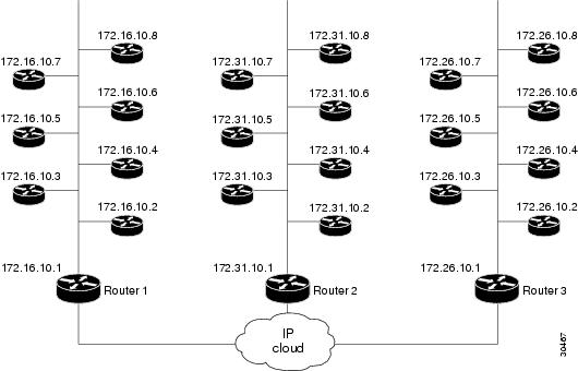
Call fallback map setup allows the decongestion of traffic caused by a high volume of call probes sent across a network to query a large number of dial peers. One router/common node can keep the distances in a cache table of the numerous IP addresses/destination peers in a network. When the fallback is queried for network congestion to a particular IP address (that is, the common node), the map addresses are searched to find the target IP address. If a match is determined, the probes are sent to the target address rather than to the particular IP address.
In Figure 2, the three routers (1, 2, and 3) keep the cache tables of distances for the destination peers behind them. When a call probe comes from somewhere in the IP cloud, the cache routers check their distance tables for the IP address/destination peer where the call probe is destined. This distance checking limits congestion on the networks behind these routers by directing the probe to the particular IP address and not to the entire network.
Figure 2 Call Fallback Map with IP Addresses
Examples
The following example specifies call fallback map address-list configurations for
172.32.10.1 and 172.46.10.1:
Router(config)# call fallback map 1 target 172.32.10.1address-list 172.32.10.2 172.32.10.3 172.32.10.4 172.32.10.5172.32.10.6 172.32.10.7 172.32.10.8Router(config)# call fallback map 2 target 172.46.10.1address-list 172.46.10.2 172.46.10.3 172.46.10.4 172.46.10.5172.46.10.6 172.46.10.7 172.46.10.8Related Commands
call fallback map subnet
To specify that the call fallback router keep a cache table by subnet addresses of distances for several destination peers, use the call fallback map subnet command in global configuration mode. To restore the default values, use the no form of this command.
call fallback map map target ip-address subnet ip-network netmask
no call fallback map map target ip-address subnet ip-network netmask
Syntax Description
map
Fallback map. Range is from 1 to 16. There is no default.
target ip-address
Target IP address.
subnet ip-network
Subnet IP address.
netmask
Network mask number.
Defaults
No call fallback maps are defined.
Command Modes
Global configuration
Command History
Usage Guidelines
Use this command when several destination peers are in one common node.
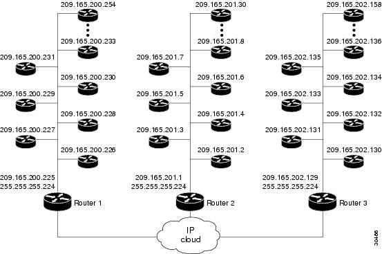
Call fallback map setup allows the decongestion of traffic caused by a high volume of call probes sent across a network to query a large number of dial peers. One router/common node can keep the distances in a cache table of the numerous IP addresses within a subnet (destination peers) in a network. When the fallback is queried for network congestion to a particular IP address (that is, the common node), the map addresses are searched to find the target IP address. If a match is determined, the probes are sent to the target address rather than to the particular IP address.
In Figure 3, the three routers (1, 2, and 3) keep the cache tables of distances for the destination peers behind them. When a call probe comes from somewhere in the IP cloud, the cache routers check their distance tables for the subnet address/destination peer where the call probe is destined. This distance checking limits congestion on the networks behind these routers by directing the probe to the particular subnet address and not to the entire network.
Figure 3 Call Fallback Map with Subnet Addresses
Examples
The following examples specify the call fallback map subnet configuration for two different IP addresses:
Router(config)# call fallback map 1 target 209.165.201.225 subnet209.165.201.224 255.255.255.224Router(config)# call fallback map 2 target 209.165.202.225 subnet209.165.202.224 255.255.255.224Related Commands
call fallback monitor
To enable the monitoring of destinations without call fallback to alternate dial peers, use the call fallback monitor command in global configuration mode. To disable monitoring without fallback, use the no form of this command.
call fallback monitor
no call fallback monitor
Syntax Description
This command has no arguments or keywords.
Defaults
Disabled
Command Modes
Global configuration
Command History
Usage Guidelines
The call fallback monitor command is used as a statistics collector of network conditions based upon probes (detailing network traffic) and connected calls. There is no H.323 call checking/rejecting as with the call fallback active command. All call requests are granted regardless of network traffic conditions.
Configure the call fallback threshold delay loss or call fallback threshold icpif command to set threshold parameters. The thresholds are ignored, but for statistics collecting, configuring one of the thresholds allows you to monitor cache entries for either delay/loss or Calculated Planning Impairment Factor (ICPIF) values.
Examples
The following example enables the call fallback monitor command:
Router(config)# call fallback monitorRelated Commands
call fallback probe-timeout
To set the timeout for a Service Assurance Agent (SAA) probe for call fallback purposes, use the call fallback probe-timeout command in global configuration mode. To restore the default value, use the no form of this command.
call fallback probe-timeout seconds
no call fallback probe-timeout
Syntax Description
Defaults
30 seconds
Command Modes
Global configuration
Command History
Usage Guidelines
SAA probes collect network traffic information based upon configured delay and loss or Calculated Planning Impairment Factor (ICPIF) values and report this information to the cache for call request determination. Use the call fallback threshold delay loss or call fallback threshold icpif commands to set the threshold parameters.
When the probe timeout expires, a new probe is sent to collect network statistics. To reduce the bandwidth taken up by the probes, increase the probe-timeout interval (seconds). Probes do not have a great effect upon bandwidth unless several thousand destinations are involved. If this is the case in your network, use a longer timeout. If you need more network traffic information, and bandwidth is not an issue, use a lower timeout. The default interval, 30 seconds, is a low timeout.
When the call fallback cache-timeout command is configured or expires, new probes are initiated for data collection.
Examples
The following example configures a 120-second interval:
Router(config)# call fallback probe-timeout 120Related Commands
call fallback reject-cause-code
To enable a specific call fallback reject cause code in case of network congestion, use the call fallback reject-cause-code command in global configuration mode. To reset the code to the default of 49, use the no form of this command.
call fallback reject-cause-code number
no call fallback reject-cause-code
Syntax Description
number
Specifies the cause code as defined in the International Telecommunication Union (ITU) standard Q.850 except the code for normal call clearing, which is code 16. The default is 49. See Table 12 for ITU cause-code numbers.
Defaults
49 (quality of service is unavailable)
Command Modes
Global configuration
Command History
Usage Guidelines
Enabling the call fallback reject-cause-code command determines the code to display when calls are rejected because of probing of network conditions.
Note
Table 12 lists the ITU cause codes and their associated displayed messages and meanings.
Examples
The following example enables the call fallback reject-cause-code command and specifies cause code 34:
call fallback reject-cause-code 34Related Commands
call fallback threshold delay loss
To specify that the call fallback threshold use only packet delay and loss values, use the call fallback threshold delay loss command in global configuration mode. To restore the default value, use the no form of this command.
call fallback threshold delay delay-value loss loss-value
no call fallback threshold delay delay-value loss loss-value
Syntax Description
Defaults
No default behavior or values.
Command Modes
Global configuration
Command History
Usage Guidelines
During times of heavy voice traffic, two parties in a conversation may notice a significant delay in transmission or hear only part of a conversation because of voice-packet loss.
Use the call fallback threshold delay loss command to configure parameters for voice quality. Lower values of delay and loss allow higher quality of voice. Call requests match the network information in the cache with the configured thresholds of delay and loss.
The amount of delay set by the call fallback threshold delay loss command should not be more than half the amount of the time-to-wait value set by the call fallback wait-timeout command; otherwise the threshold delay will not work correctly. Because the default value of the call fallback wait-timeout command is set to 300 milliseconds, the user can configure a delay of up to 150 milliseconds for the call fallback threshold delay loss command. If the user wants to configure a higher threshold, the time-to-wait delay has to be increased from its default (300 milliseconds) using the call fallback wait-timeout command.
Note
If you enable the call fallback active command, the call fallback subsystem uses the last cache entry compared with the configured delay/loss threshold to determine whether the call is connected or denied. If you enable the call fallback monitor command, all calls are connected, regardless of the configured threshold or voice quality. In this case, configuring the call fallback threshold delay loss command allows you to collect network statistics for further tracking.
Note
Setting this command does not affect bandwidth. Available bandwidth for call requests is determined by the call fallback subsystem using probes. The number of probes on the network affects bandwidth.
Examples
The following example configures a threshold delay of 20 milliseconds and a threshold loss of 50 percent:
Router(config)# call fallback threshold delay 20 loss 50Related Commands
call fallback threshold icpif
To specify that call fallback use the Calculated Planning Impairment Factor (ICPIF) threshold, use the call fallback threshold icpif command in global configuration mode. To restore the default value, use the no form of this command.
call fallback threshold icpif threshold-value
no call fallback threshold icpif
Syntax Description
Defaults
5
Command Modes
Global configuration
Command History
Usage Guidelines
During times of heavy voice traffic, the parties in a conversation may notice a significant delay in transmission or hear only part of a conversation because of voice-packet loss.
Use the call fallback threshold icpif command to configure parameters for voice quality. A low ICPIF value allows for higher quality of voice. Call requests match the network information in the cache with the configured ICPIF threshold. If you enable the call fallback active command, the call fallback subsystem uses the last cache entry compared with the configured ICPIF threshold to determine whether the call is connected or denied. If you enable the call fallback monitor command, all calls are connected regardless of the configured threshold or voice quality. In this case, configuring the call fallback threshold icpif command allows you to collect network statistics for further tracking.
A lower ICPIF value tolerates less delay and loss of voice packets (according to ICPIF calculations). Use lower values for higher quality of voice. Configuring a value of 34 equates to 100 percent packet loss.
The ICPIF is calculated and used according to the International Telecommunication Union (ITU) G.113 specification.
Note
Setting this command does not affect bandwidth. Available bandwidth for call requests is determined by the call fallback subsystem using probes. The number of probes on the network affects bandwidth.
Examples
The following example sets the ICPIF threshold to 20:
Router(config)# call fallback threshold icpif 20Related Commands
call fallback wait-timeout
To modify the time to wait for a response to a probe, use the call fallback wait-timeout command in global configuration mode. To return to the default value, use the no form of this command.
call fallback wait-timeout milliseconds
no call fallback wait-timeout milliseconds
Syntax Description
milliseconds
Specifies the time-to-wait value in milliseconds. The range is 100 to 3000 milliseconds.
Defaults
300 milliseconds
Command Modes
Global configuration
Command History
Usage Guidelines
This command is enabled by default and the time to wait for a response to a probe is set to 300 milliseconds. This command allows the user to modify the amount of time to wait for a response to a probe. The milliseconds argument allows the user to configure a time-to-wait value between 100 milliseconds and 3000 milliseconds. A user who has a higher-latency network may want to increase the value of the default timer.
The time-to-wait period set by the call fallback wait-timeout command should always be greater than or equal to twice the amount of the threshold delay time set by the call fallback threshold delay loss command; otherwise the probe will fail.
Note
Examples
The following example sets the value of the amount of time to wait for a response to a probe to 200 milliseconds:
call fallback wait-timeout 200Related Commands
call fallback threshold delay loss
Specifies the call fallback threshold delay and loss values.
call language voice
To configure an external Tool Command Language (TCL) module for use with an interactive voice response (IVR) application, use the call language voice command in global configuration mode.
call language voice language url
Syntax Description
language
Two-character prefix for the language; for example, "en" for English or "ru" for Russian.
url
URL that points to the TCL module.
Defaults
No default behavior or values
Command Modes
Global configuration
Command History
Usage Guidelines
The built-in languages are English (en), Chinese (ch), and Spanish (sp). If you specify "en", "ch", or "sp", the new TCL module replaces the built-in language functionality. When you add a new TCL module, you create your own prefix to identify the language. When you configure and load the new languages, any upper-layer application (TCL IVR) can use the language.
You can use the language prefix in the language argument of any call application voice command. The language and the text-to-speech (TTS) notations are available for the IVR application to use after they are defined by the TCL module.
Examples
The following example adds Russian (ru) as a TCL module:
call language voice ru tftp://box/unix/scripts/multi-lang/ru_translate.tclRelated Commands
call language voice load
To load or reload a Tool Command Language (TCL) module from the configured URL location, use the call language voice load command in EXEC mode.
call language voice load language
Syntax Description
language
The two-character prefix configured with the call language voice command in global configuration mode; for example, "en" for English or "ru" for Russian.
Defaults
No default behavior or values
Command Modes
EXEC
Command History
Usage Guidelines
You cannot use this command if the interactive voice response (IVR) application using the language that you want to configure has an active call. A language that is configured under an IVR application is not necessarily in use. To determine if a call is active, use the show call application voice command.
Examples
The following example loads French (fr) into memory:
call language voice load frRelated Commands
call rscmon update-timer
To change the value of the resource monitor throttle timer, use the call rscmon update-timer command in privileged EXEC mode. To revert to the default value, use the no form of this command.
call rscmon update-timer duration
no call rscmon update-timer
Syntax Description
duration
Duration of the resource monitor throttle timer, in milliseconds. Range is from 20 to 3500. The default is 2000.
Defaults
2000 milliseconds
Command Modes
Privileged EXEC
Command History
Usage Guidelines
This command specifies the duration of the resource monitor throttle timer. When events are delivered to the resource monitor process, the throttle timer is started and the event is processed after the timer expires (unless the event is a high-priority event). The timer ultimately affects the time it takes the gateway to send Resource Availability Indicator (RAI) messages to the gatekeeper. This command allows you to vary the timer according to your needs.
Examples
The following example shows how the timer is to be configured:
Router(config)# call rscmon update-timer 1000Related Commands
resource threshold
Configures a gateway to report H.323 resource availability to its gatekeeper.
call rsvp-sync
To enable synchronization between Resource Reservation Protocol (RSVP) signaling and the voice signaling protocol, use the call rsvp-sync command in global configuration mode. To disable synchronization, use the no form of this command.
call rsvp-sync
no call rsvp-sync
Syntax Description
This command has no keywords or arguments.
Defaults
Synchronization is enabled between RSVP and the voice signaling protocol (for example, H.323).
Command Modes
Global configuration
Command History
Usage Guidelines
The call rsvp-sync command is enabled by default.
Examples
The following example enables synchronization between RSVP and the voice signaling protocol:
call rsvp-syncRelated Commands
call rsvp-sync resv-timer
To set the timer on the terminating VoIP gateway for completing RSVP reservation setups, use the call rsvp-sync resv-timer command in global configuration mode. To restore the default value, use the no form of this command.
call rsvp-sync resv-timer seconds
no call rsvp-sync resv-timer
Syntax Description
seconds
Number of seconds in which the reservation setup must be completed, in both directions. Range is from 1 to 60. The default is 10.
Defaults
10 seconds
Command Modes
Global configuration
Command History
Usage Guidelines
The reservation timer is started on the terminating gateway when the session protocol receives an indication of the incoming call. This timer is not set on the originating gateway because the resource reservation is confirmed at the terminating gateway. If the reservation timer expires before the RSVP setup is complete, the outcome of the call depends on the acceptable quality of service (QoS) level configured in the dial peer; either the call proceeds without any bandwidth reservation or it is released. The timer must be set long enough to allow calls to complete but short enough to free up resources. The optimum number of seconds depends on the number of hops between the participating gateways and the delay characteristics of the network.
Examples
The following example sets the reservation timer to 30 seconds:
call rsvp-sync resv-timer 30Related Commands
call service stop
To shut down VoIP call service under the H.323 or SIP submode on a gateway, use the call service stop command in voice service configuration mode. To enable VoIP call service, use the no form of this command.
call service stop [forced] [maintain-registration]
no call service stop
Syntax Description
forced
(Optional) Forces the gateway to immediately terminate all in-progress calls.
maintain-registration
(Optional) Forces the gateway to remain registered with the gatekeeper.
Defaults
Call service is enabled
Command Modes
Voice service configuration
Command History
Usage Guidelines
The call service stop command affects call processing only for the given submode. This command overrides the functionality of the shutdown command for the affected submode.
Examples
The following example shows SIP call service being shutdown on a Cisco gateway:
enableconfigure terminalvoice service voipsipcall service stopThe following example shows H.323 call service being enabled on a Cisco gateway:
enableconfigure terminalvoice service voiph323no call service stopRelated Commands
call spike
To configure limit on the number of incoming calls received in a short period of time, use the call spike command in global configuration mode. To disable this command, use the no form of this command.
call spike call-number [steps number-of-steps size milliseconds]
no call spike
Syntax Description
Defaults
steps—The default is 5
size—The default is 200Command Modes
Global configuration
Command History
Usage Guidelines
A call spike occurs when a large number of incoming calls arrive from the Public Switched Telephone Network (PSTN) in a short period of time (for example, 100 incoming calls in 10 milliseconds). Setting this command allows you to control the number of call requests that can be received in a configured time period.
Examples
The following configuration of the call spike command has a call-number of 30, a sliding window of 10 steps, and a step size of 2000 milliseconds.
call spike 30 steps 10 size 2000Related Commands
call start
To force the H.323 Version 2 gateway to use fast connect or slow connect procedures for a dial peer, use the call start command in H.323 voice-service configuration mode. To restore the system setting, use the no form of this command.
call start {fast | slow | system}
no call start
Syntax Description
fast
Gateway uses H.323 Version 2 (fast connect) procedures.
slow
Gateway uses H.323 Version 1 (slow connect) procedures.
system
Gateway defaults to the voice-service configuration.
Defaults
system
Command Modes
H.323 voice-service configuration
Command History
Usage Guidelines
In Cisco IOS Release 12.1(3)XI and later, H.323 Voice over IP (VoIP) gateways by default use H.323 Version 2 (fast connect) for all calls, including those initiating RSVP. Previously, gateways used only slow connect procedures for RSVP calls. To enable Cisco IOS Release 12.1(3)XI gateways to be backward compatible with earlier releases of Cisco IOS Release 12.1 T, the call start command allows the originating gateway to initiate calls using slow connect.
The call start command is configured as part of the voice class assigned to an individual VoIP dial peer. It takes precedence over the h323 call start command, which applies globally to all VoIP calls, unless the system keyword is selected. If the system keyword is used, the gateway defaults to the Version 2.
Examples
The following example selects slow connect for the voice class 1000:
voice service class h323 1000call start slow!dial-peer voice 210 voipvoice-class h323 1000The following example shows the gateway configured to use the H.323 Version 1 (Slow Connect) procedures.
h323call start slowRelated Commands
call threshold global
To enable the global resources of a gateway, use the call threshold global command in global configuration mode. To disable the global resources of the gateway, use the no form of this command.
call threshold global trigger-name low value high value [busyout] [treatment]
no call threshold global trigger-name
Syntax Description
Defaults
The default is busyout and treatment for global resource triggers
Command Modes
Global configuration
Command History
Usage Guidelines
Use this command to enable a trigger and define associated parameters to allow or disallow new calls on the router. Action is enabled when the trigger value goes above the value specified by the high keyword and is disabled when the trigger drops below the value specified by the low keyword.
You can configure these triggers to calculate Resource Availability Indicator (RAI) information. An RAI is forwarded to a gatekeeper so that it can make call admission decisions. You can configure a trigger that is global to a router or is specific to an interface.
Examples
The following example shows how to busy out the total calls when a low of 5 or a high of 5,000 is reached:
call threshold global total-calls low 5 high 5000 busyoutThe following example shows how to busy out the average CPU utilization if a low of 5 percent or a high of 65 percent is reached:
call threshold global cpu-avg low 5 high 65 busyoutRelated Commands
call threshold interface
To enable the interface resources of a gateway, use the call threshold interface command in global configuration mode. To disable the interface resources of the gateway, use the no form of this command.
call threshold interface interface-name interface-number int-calls low value high value
no call threshold interface interface-name interface-number int-calls
Syntax Description
Defaults
No default behavior or values
Command Modes
Global configuration
Command History
Usage Guidelines
Use this command to enable a trigger and define associated parameters to allow or disallow new calls on the router. You can configure these triggers to calculate Resource Availability Indicator (RAI) information. An RAI is forwarded to a gatekeeper so that it can make call admission decisions. You can configure a trigger that is specific to an interface. Use the interface attribute to apply interface-related triggers.
Examples
The following example enables thresholds as low as 5 and as high as 2500 for interface calls on interface Ethernet 0/1:
call threshold interface Ethernet 0/1 int-calls low 5 high 2500Related Commands
call threshold poll-interval
To enable a polling interval threshold for CPU or memory, use the call threshold poll-interval command in global configuration mode. To disable this command, use the no form of this command.
call threshold poll-interval {cpu-average | memory} seconds
no call threshold poll-interval {cpu-average | memory}
Syntax Description
Defaults
Cpu-average: 60 seconds
Memory: 5 secondsCommand Modes
Global configuration
Command History
Examples
The following example shows how to enable a polling interval threshold for memory of 10 seconds:
call threshold poll-interval memory 10Related Commands
call treatment
To configure how calls should be processed when local resources are unavailable, use the call treatment command in global configuration mode. To disable call treatment, use the no form of this command.
call treatment {on | action action [value] | cause-code cause-code | isdn-reject value}
no call treatment {on | action action [value] | cause-code cause-code | isdn-reject value}
Syntax Description
Defaults
Treatment is inactive
Command Modes
Global configuration
Command History
Usage Guidelines
Use this command to enable a trigger and define associated parameters to disconnect (with cause code), or hairpin, or whether a message, or busy tone is played to the user.
Examples
The following example shows how to enable the call treatment feature with a "hairpin" action:
call treatment oncall treatment action hairpinThe following example shows how to enable the call treatment feature with a "playmsg" action. The file "congestion.au"plays to the caller when local resources are not available to handle the call.
call treatment oncall treatment action playmsg tftp://keyer/prompts/conjestion.auThe following example shows how to configure a call treatment cause code to reply with "no-Qos" when local resources are unavailable to process a call:
call treatment oncall treatment cause-code no-QosRelated Commands
call-agent
To define the call agent for a Media Gateway Control Protocol (MGCP) profile, use the call-agent command in MGCP profile configuration mode. To return to the default values, use the no form of this command.
call-agent {dns-name | ip-address} [port] [service-type type] [version protocol-version]
no call-agent
Syntax Description
Defaults
The default call-agent UDP port is 2727 for MGCP 1.0, Network-based Call Signaling (NCS) 1.0, and Trunking Gateway Control Protocol (TGCP) 1.0.
The default call-agent UDP port is 2427 for MGCP 0.1 and Simple Gateway Control Protocol (SGCP).
The default service type and version is MGCP 0.1.Command Modes
MGCP profile configuration
Command History
Usage Guidelines
This command is used when values for a MGCP profile are configured.
Call-agent configuration for an MGCP profile (with this command) and global call-agent configuration (with the mgcp call-agent command) are mutually exclusive; the first to be configured on an endpoint blocks configuration of the other on the same endpoint.
Identifying call agents by Domain Name System (DNS) name rather than by IP address in the call-agent command provides call-agent redundancy, because a DNS name can have more than one IP address associated with it. If a call agent is identified by a DNS name and a message from the gateway fails to reach the call agent, the max1 lookup and max2 lookup commands enable a search from the DNS lookup table for a backup call agent at a different IP address.
The port argument configures the call agent port number (the UDP port over which the gateway sends messages to the call agent). The reverse, or the gateway port number (the UDP port over which the gateway receives messages from the call agent), is configured by specifying a port number in the mgcp command.
The service type mgcp supports the Restart In Progress (RSIP) error messages sent by the gateway if the mgcp sgcp restart notify command is enabled. The service type sgcp ignores the RSIP messages.
Examples
The following example defines a call agent for the MGCP profile named "tgcp_trunk":
Router(config)# mgcp profile tgcp_trunkRouter(config-mgcp-profile)# call-agent 10.13.93.3 2500 service-type tgcp version 1.0Related Commands
call-block (dial-peer)
To enable blocking of incoming calls, use the call-block command in dial-peer configuration mode. To return to the default value, use the no form of this command.
call-block {disconnect-cause incoming {call-reject | invalid-number | unassigned-number | user-busy} | translation-profile incoming name}
no call-block {disconnect-cause incoming {call-reject | invalid-number | unassigned-number | user-busy} | translation-profile incoming name}
Syntax Description
Defaults
Disconnect cause: No Service (once the call-blocking translation profile is defined)
Translation profile: No default behavior or valuesCommand Modes
Dial-peer configuration
Command History
Usage Guidelines
The incoming call can be blocked from the gateway if one of the call numbers (calling, called, or redirect) is matched with the reject translation rule of the incoming call-blocking translation profile.
The cause value is returned to the source of the call when a call is blocked during the incoming call-number translation.
This command is supported in POTS, VoIP, VoFR, and VoATM dial-peer configuration. For VoATM, only AAL5 calls are supported.
Examples
The following example assigns the translation profile "westcoast" to be used for incoming calls and returns the message "invalid number" as a cause for blocked calls:
Router(config)# dial-peer voice 5 potsRouter(config-dial-peer)# call-block translation-profile incoming westcoastRouter(config-dial-peer)# call-block disconnect-cause incoming invalid-numberRelated Commands
call-denial
The call-denial command is replaced by the call threshold global command. See the call threshold global command for more information.
called-number (dial-peer)
To enable an incoming Voice over Frame Relay (VoFR) call leg to get bridged to the correct plain old telephone service (POTS) call leg when a static FRF.11 trunk connection is used, use the called-number command in dial peer configuration mode. To disable a static trunk connection, use the no form of this command.
called-number string
no called-number
Syntax Description
string
A string of digits, including wildcards, that specifies the telephone number of the voice port dial peer.
Defaults
This command is disabled
Command Modes
Dial peer configuration
Command History
12.0(4)T
This command was introduced on the Cisco 2600 series and Cisco 3600 series.
Usage Guidelines
This command applies to the Cisco 2600 and Cisco 3600 series routers only. It is ignored on the Cisco MC3810 and on the Cisco 7200 series.
The called-number command is used only when the dial peer type is VoFR and you are using the frf11-trunk (FRF.11) session protocol. It is ignored at all times on the Cisco MC3810 multiservice concentrator and on all other platforms when using the Cisco-switched session protocol.
Because FRF.11 does not provide any end-to-end messaging to manage a trunk, the called-number command is necessary to allow the router to establish an incoming trunk connection. The E.164 number is used to find a matching dial peer during call setup.
Examples
The following example shows how to configure a Cisco 2600 series routers or 3600 series router for a static FRF.11 trunk connection to a specific telephone number (555-2150), beginning in global configuration mode:
voice-port 1/0/0connection trunk 55Router0exitdial-peer voice 100 potsdestination pattern 5552150exitdial-peer voice 200 vofrsession protocol frf11-trunkcalled-number 5552150destination pattern 55Router0Related Commands
caller-id
To enable caller ID, use the caller-id command in dial peer configuration mode. To disable caller ID, use the no form of the command.
caller-id
no caller-id
Syntax Description
This command contains no arguments or keywords.
Defaults
Caller ID is disabled
Command Modes
Dial peer configuration
Command History
12.1.(2)XF
This command was introduced on the Cisco 800 series routers.
12.1(5)T
This command was integrated into Cisco IOS Release 12.1(5)T.
Usage Guidelines
This command is available on Cisco 800 series routers that have plain old telephone service (POTS) ports. The command is effective only if you subscribe to caller ID service. If you enable caller ID on a router without subscribing to the caller ID service, caller ID information does not appear on the telephone display.
The configuration of caller ID must match the device connected to the POTS port. That is, if a telephone supports the caller ID feature, use the command caller-id to enable the feature. If the telephone does not support the caller ID feature, use the command default or disable the caller ID feature. Odd ringing behavior might occur if the caller ID feature is disabled when it is a supported telephone feature or enabled when it is not a supported telephone feature.
Note
Examples
The following example enables a router to use the caller ID feature:
dial-peer voice 1 potscaller-idRelated Commands
caller-id alerting dsp-pre-alloc
To statically allocate a digital signal processor (DSP) resource for receiving caller ID information for on-hook (Type 1) Caller ID at a receiving Foreign Exchange Office (FXO) voice port, use the caller-id alerting dsp-pre-alloc command in voice-port configuration mode. To disable the command's effect, use the no form of this command.
caller-id alerting dsp-pre-alloc
no caller-id alerting dsp-pre-alloc
Syntax Description
This command contains no keywords or arguments.
Defaults
No pre-allocation of DSP resources
Command Modes
Voice-port configuration
Command History
12.1(2)XH
This command was introduced on the Cisco MC3810, Cisco 2600 series, and Cisco 3600 series.
12.1(3)T
This command was integrated into Cisco IOS Release 12.1(3)T.
Usage Guidelines
The caller-id alerting dsp-pre-alloc command may be required on an FXO port if the central office uses line polarity reversal to signal the start of Caller-ID information transmission. Pre-allocating a DSP allows the DSP to listen for Caller-ID information continuously without requiring an alerting signal from the CO.
This command is the FXO counterpart to the caller-id alerting line-reversal command, which is applied to the Foreign Exchange Station (sending) end of the Caller-ID call.
Note
Examples
The following example configures a voice port on a Cisco 2600 series or Cisco 3600 series router where Caller-ID information is received:
voice-port 1/0/1cptone UScaller-id enablecaller-id alerting line-reversalcaller-id alerting dsp-pre-allocThe following example configures a voice port on a Cisco MC3810 where Caller-ID information is received:
voice-port 1/0cptone northamericacaller-id enablecaller-id alerting line-reversalcaller-id alerting dsp-pre-allocRelated Commands
caller-id alerting line-reversal
Sets the line-reversal method of Caller-ID call alerting.
caller-id alerting line-reversal
To set the line-reversal alerting method for Caller-ID information for on-hook (Type 1) Caller ID at a sending Foreign Exchange Station (FXS) voice port, use the caller-id alerting line-reversal command in voice-port configuration mode. To disable the command's effect, use the no form of this command.
caller-id alerting line-reversal
no caller-id alerting line-reversal
Syntax Description
This command has no keywords or arguments.
Defaults
No line-reversal alert
Command Modes
Voice-port configuration
Command History
12.1(2)XH
This command was introduced on the Cisco 2600 series, and Cisco 3600 series and Cisco MC3810.
12.1(3)T
This command was integrated into Cisco IOS Release 12.1(3)T.
Usage Guidelines
This command is only required when the telephone device attached to an FXS port requires the line-reversal method to signal the start of a Caller-ID transmission. Use it on FXS voice ports that send Caller-ID information.
This command is the FXS counterpart to the caller-id alerting dsp-pre-alloc command, which is applied to the FXO (receiving) end of the Caller-ID call with the line-reversal alerting method.
Note
Examples
The following example configures a voice port on a Cisco 2600 or 3600 series router from which Caller-ID information is sent:
voice-port 1/0/1cptone USstation name A. Personstation number 4085551111caller-id alerting line-reversalcaller-id alerting dsp-pre-allocThe following example configures a voice port on a Cisco MC3810 from which Caller-ID information is sent:
voice-port 1/0cptone northamericastation name A. Personstation number 4085551111caller-id alerting line-reversalcaller-id alerting dsp-pre-allocRelated Commands
caller-id alerting dsp-pre-alloc
At the receiving end of a line-reversal alerting Caller-ID call, pre-allocates DSPs for caller ID calls.
caller-id alerting pre-ring
To set a 250-millisecond pre-ring alerting method for caller ID information for on-hook (Type 1) Caller ID at a sending Foreign Exchange Station (FXS) voice port, use the caller-id alerting pre-ring command in voice-port configuration mode. To disable the command, use the no form of this command.
caller-id alerting pre-ring
no caller-id alerting pre-ring
Syntax Description
This command has no keywords or arguments.
Defaults
No pre-ring alert
Command Modes
Voice-port configuration
Command History
12.1(2)XH
This command was introduced on the Cisco MC3810, Cisco 2600 series, and Cisco 3600 series.
12.1(3)T
This command was integrated into Cisco IOS Release 12.1(3)T.
Usage Guidelines
This command is required only when the telephone device attached to an FXS port requires the pre-ring (immediate ring) method to signal the start of caller ID transmission. Use it on FXS voice ports that send caller ID information. This command allows the FXS port to send a short pre-ring preceding the normal ring cadence. On an FXO port, an incoming pre-ring (immediate ring) is simply counted as a normal ring using the caller-id alerting ring command.
Note
Examples
The following example configures a voice port on a Cisco 2600 series or Cisco 3600 series router from which caller ID information is sent:
voice-port 1/0/1cptone USstation name A. Personstation number 4085551111caller-id alerting pre-ringThe following example configures a voice port on a Cisco MC3810 from which caller ID information is sent:
voice-port 1/0cptone northamericastation name A. Personstation number 4085551111caller-id alerting pre-ring 1Related Commands
caller-id alerting ring
To set the ring-cycle method for receiving caller ID information for on-hook (Type 1) Caller ID at a receiving Foreign Exchange Office (FXO) or a sending Foreign Exchange Station (FXS) voice port, use the caller-id alerting ring command in voice-port configuration mode. To set the command to the default, use the no form of this command.
caller-id alerting ring {1 | 2}
no caller-id alerting ring
Syntax Description
Defaults
1
Command Modes
Voice-port configuration
Command History
12.1(2)XH
This command was introduced on the Cisco 2600 series, Cisco 3600 series and Cisco MC3810.
12.1(3)T
This command was integrated into Cisco IOS Release 12.1(3)T.
Usage Guidelines
This setting is determined by the Bellcore/Telcordia or ETSI standard that your telephone service provider uses for caller ID. Use it on FXO loop-start and ground-start voice ports where caller ID information arrives and on FXS voice ports from which caller ID information is sent.
This setting must match on the sending and receiving ends on both ends of the telephone line connection.
Note
Examples
The following example configures a Cisco 2600 series or Cisco 3600 series router voice port where caller ID information is received:
voice-port 1/0/1cptone UScaller-id alerting ring 1The following example configures a Cisco 2600 series or Cisco 3600 series router voice port from which caller ID information is sent:
voice-port 1/0/1cptone northamericastation name A. Personstation number 4085551111caller-id alerting ring 1The following example configures a Cisco MC3810 voice port where caller ID information is received:
voice-port 1/0cptone northamericacaller-id alerting ring 1The following example configures a Cisco MC3810 voice port from which caller ID information is sent:
voice-port 1/0cptone northamericastation name A. Personstation number 4085551111caller-id alerting ring 1Related Commands
caller-id attenuation
To set the attenuation for caller ID at a receiving Foreign Exchange Office (FXO) voice port, use the caller-id attenuation command in voice-port configuration mode. To set the command to the default, use the no form of this command.
caller-id attenuation [attenuation]
no caller-id attenuation
Syntax Description
Defaults
The default value is 14 decibels (dB), signal level of -14 dBm
Command Modes
Voice-port configuration
Command History
12.1(2)XH
This command was introduced on and Cisco 2600 series, Cisco 3600 series and the Cisco MC3810.
12.1(3)T
This command was integrated into Cisco IOS Release 12.1(3)T.
Usage Guidelines
Use this setting to specify the attenuation for a caller ID FXO port. If the setting is not used, the attenuation is set to 14 decibels (dB), signal level of -14 dBm.
Note
Examples
The following example configures a Cisco 2600 series or Cisco 3600 series router voice port where caller ID information is received:
voice-port 1/0/1cptone UScaller-id attenuation 0The following example configures a Cisco MC3810 voice port where caller ID information is received:
voice-port 1/0cptone northamericacaller-id attenuation 0caller-id block
To request the blocking of the display of caller ID information at the far end of a call from calls originated at a Foreign Exchange Station (FXS) port, use the caller-id block command in voice-port configuration mode at the originating FXS voice port. To allow the display of caller ID information, use the no form of this command.
caller-id block
no caller-id block
Syntax Description
This command has no keywords or arguments.
Defaults
No blocking of caller ID information
Command Modes
Voice-port configuration
Command History
12.1(2)XH
This command was introduced on and Cisco 2600 series, Cisco 3600 series and the Cisco MC3810.
12.1(3)T
This command was integrated into Cisco IOS Release 12.1(3)T.
Usage Guidelines
This command is used on FXS voice ports that are used to originate on-net telephone calls. This command affects all calls sent to a far-end FXS station from the configured originating FXS station. Calling number and called number are provided in the H.225 setup message for VoIP, through the H.225 Octet 3A field. Calling name information is included in a display information element.
Note
This command applies to the Cisco MC3810 and to Cisco 2600 series and 3600 series routers.
Note
Examples
The following example configures a Cisco 2600 series or Cisco 3600 series router voice port from which caller ID information is sent:
voice-port 1/0/1cptone USstation name A. Personstation number 4085551111caller-id blockThe following example configures a Cisco MC3810 voice port from which caller ID information is sent:
voice-port 1/0cptone northamericastation name A. Personstation number 4085551111caller-id blockRelated Commands
caller-id block (ephone-dn)
To configure caller-ID blocking for outbound calls, use the caller-id block command in ephone-dn configuration mode. To disable caller-ID blocking, use the no form of this command.
caller-id block
no caller-id block
Syntax Description
This command has no arguments or keywords.
Defaults
Caller ID is not blocked on calls originating from a Cisco IP phone
Command Modes
Ephone-dn configuration
Command History
Usage Guidelines
The caller-id block command sets caller-ID blocking for outbound calls originating from the specific directory number (ephone-dn). This command requests that the far-end gateway device block display of the calling party information, for calls received by the far-end gateway from the ephone-dn. This command does not effect the ephone-dn calling party information display for inbound calls received by the ephone-dn.
Examples
The following example shows how to set caller ID blocking for the directory number 5001:
Router(config) ephone-dn 1Router(config-ephone-dn)# number 5001Router(config-ephone-dn)# caller-id blockRelated Commands
ephone
Enters ephone configuration mode.
ephone-dn
Enters ephone-dn configuration mode.
caller-id enable
To allow the sending or receiving of caller-ID information, use the caller-id enable command in voice-port configuration mode at the sending foreign exchange station (FXS) voice port or the receiving foreign exchange office (FXO) voice port. To disable the sending or receiving of caller-ID information, use the no form of this command.
caller-id enable
no caller-id enable
Syntax Description
This command has no keywords or arguments.
Defaults
No sending or receiving of caller-ID information
Command Modes
Voice-port configuration
Command History
12.1(2)XH
This command was introduced on and Cisco 2600 series, Cisco 3600 series and the Cisco MC3810.
12.1(3)T
This command was integrated into Cisco IOS Release 12.1(3)T.
Usage Guidelines
This command applies to FXS voice ports that send caller-ID information and to FXO ports that receive caller-ID information. Calling number and called number are provided in the H.225.0 setup message for VoIP, through the H.225.0 Octet 3A field. Calling name information is included in a display information element.
Note
If the station name, station number, or a caller-id alerting command is configured on the voice port, these automatically enable caller ID, and the caller-id enable command is not necessary.
Note
This command applies to the Cisco MC3810 and to Cisco 2600 and Cisco 3600 series routers.
Note
Examples
The following example configures a Cisco 2600 series or Cisco 3600 series router voice port at which caller-ID information is received:
voice-port 1/0/1cptone UScaller-id enableThe following example configures a Cisco 2600 series or Cisco 3600 series router voice port from which caller-ID information is sent:
voice-port 1/0/1cptone northamericastation name A. Personstation number 4085551111caller-id enableThe following example configures a Cisco MC3810 voice port where caller-ID information is received:
voice-port 1/0cptone northamericacaller-id enableThe following example configures a Cisco MC3810 voice port from which caller-ID information is sent:
voice-port 1/0cptone northamericastation name A. Personstation number 4085551111caller-id enableRelated Commands
caller-number
To associate a type of ring cadence with a specific caller ID, use the caller-number command in dial-peer voice configuration mode. To disable the type of ring cadence for a specific caller ID, use the no form of this command.
caller-number number ring cadence
no caller-number number ring cadence
Syntax Description
Defaults
The router does not associate any caller ID with a cadence level. Therefore, there is no distinctive ring.
Command Modes
Dial-peer voice configuration
Command History
12.2(8)T
This command was introduced on Cisco 803, Cisco 804, and Cisco 813 routers.
Usage Guidelines
You can enter the caller-number command for each POTS port. There is a maximum of 20 caller IDs that can be associated with distinct ring cadences. After 20 numbers per port have been set, you cannot set more numbers (and their ring cadences) for that port until you have removed any of the numbers that have already been set. To remove already-set numbers and their ring cadences, use the no form of the caller-number command.
The command must be set within each dial peer. Because there are 6 dial peers available, you can specify 20 caller IDs per port, for a maximum of 120 caller ID numbers.
Note
To disable distinctive ringing based on a caller ID number, configure the no caller-number command. Disabling the ringing removes the specific cadence that has been set for that particular number. If you have set 20 numbers and their ring cadences, you need to set the no caller-number command for each of the 20 numbers.
Use the show running-config command to check distinctive ringing status.
Examples
The following output examples show that three caller ID numbers and their ring cadences have been set for POTS port 1 and that five caller ID numbers and their ring cadences have been set for POTS port 2.
dial-peer voice 1 potsdestination-pattern 5555555port 1no call-waitingring 0volume 4caller-number 1111111 ring 2caller-number 2222222 ring 1caller-number 3333333 ring 1dial-peer voice 2 potsdestination-pattern 5552222port 2no call-waitingring 0volume 2caller-number 4444444 ring 1caller-number 6666666 ring 2caller-number 7777777 ring 0caller-number 8888888 ring 1caller-number 9999999 ring 2Related Commands
call-waiting
Enables call waiting.
volume
Configures the receiver volume level in the router.
call-forward all (ephone-dn)
To configure call forwarding so that all the incoming calls on one of the lines of a Cisco IP phone are forwarded from that telephone to another telephone, use the call-forward all command in ephone-dn configuration mode. To disable call forwarding, use the no form of this command.
call-forward all directory-number
no call-forward all [directory-number]
Syntax Description
Defaults
No default behavior or values
Command Modes
Ephone-dn configuration
Command History
Usage Guidelines
The call forwarding mechanism is applied to the individual telephone line (directory number) and cannot be configured for individual Cisco IP phones.
Note
Examples
The following example shows how to set call forwarding of all calls on line 1, directory number 5001, to directory number 5005. All incoming calls destined for extension 5001 are forwarded to another Cisco IP phone with the extension number 5005:
Router(config)# ephone-dn 1Router(config-ephone-dn)# number 5001Router(config-ephone-dn)# call-forward all 5005Related Commands
call-forward busy (cm-fallback)
To configure call forwarding to another number when a Cisco IP phone is busy, use the call-forward busy command in call-manager-fallback configuration mode. To disable call forwarding, use the no form of this command.
call-forward busy directory-number
no call-forward busy [directory-number]
Syntax Description
Defaults
No default behavior or values
Command Modes
Call-manager-fallback configuration
Command History
Usage Guidelines
The call-forward busy command configures call forwarding to another number when a Cisco IP phone is busy. The call forwarding mechanism is applied globally to all phones that register during fallback.
Examples
The following example shows how to set call forwarding to extension number 5005 on busy for an incoming call to any IP phone extension number:
Router(config)# call-manger-fallbackRouter(config-cm-fallback)# call-forward busy 5005
Note
Related Commands
call-forward busy (ephone-dn)
To configure call forwarding to another number when the Cisco IP phone is busy, use the call-forward busy command in ephone-dn configuration mode. To disable call forwarding, use the no form of this command.
call-forward busy directory-number
no call-forward busy [directory-number]
Syntax Description
Defaults
No default behavior or values
Command Modes
Ephone-dn configuration
Command History
Usage Guidelines
The call forwarding mechanism is applied to the individual telephone line (directory number) and cannot be configured individual Cisco IP phones.
Note
Examples
The following example shows how to set call forwarding of incoming calls to directory number 5005 when line 1, directory number 5001, is busy:
Router(config)# ephone-dn 1Router(config-ephone-dn)# number 5001Router(config-ephone-dn)# call-forward busy 5005Related Commands
call-forward noan (cm-fallback)
To configure call forwarding to another number when no answer is received from a Cisco IP phone, use the call-forward noan command in call-manager-fallback configuration mode. To disable call forwarding, use the no form of this command.
call-forward noan directory-number timeout seconds
no call-forward noan [directory-number]
Syntax Description
Defaults
No default behavior or values
Command Modes
Call-manager-fallback configuration
Command History
Usage Guidelines
The call-forward noan command configures call forwarding to another number when no answer is received from a Cisco IP phone. The call forwarding mechanism is applied globally to all phones that register during fallback. The timeout keyword sets the waiting time before the call is forwarded to another phone.
Examples
The following example shows how to set call forwarding of incoming calls to directory number 5005 when line 1, directory number 5001, does not answer. The timeout before the call is forwarded to the directory number 5005 is set for 10 seconds:
Router(config)# call-manager-fallbackRouter(config-cm-fallback)# call-forward noan 5005 timeout 10
Note
Related Commands
call-forward noan (ephone-dn)
To configure call forwarding to another number when no answer is received from a Cisco IP phone, use the call-forward noan command in ephone-dn configuration mode. To disable call forwarding, use the no form of this command.
call-forward noan directory-number timeout seconds
no call-forward noan [directory-number]
Syntax Description
Defaults
No default behavior or values
Command Modes
Ephone-dn configuration
Command History
Usage Guidelines
The call forwarding mechanism is applied to the individual telephone line (directory number) and cannot be configured for individual Cisco IP phones.
Examples
The following example shows how to set call forwarding of incoming calls to directory number 5005 when line 1, directory number 5001, does not answer. The timeout before the call is forwarded to the directory number 5005 is set for 10 seconds:
Router(config)# ephone-dn 1Router(config-ephone-dn)# number 5001Router(config-ephone-dn)# call-forward noan 5005 timeout 10Related Commands
call-forward pattern
To specify a pattern for calling-party numbers that are able to support the ITU-T H.450.3 standard for call forwarding, use the call-forward pattern command in telephony-service configuration mode. To remove the pattern, use the no form of this command.
call-forward pattern pattern
no call-forward pattern pattern
Syntax Description
Defaults
No default behavior or values
Command Modes
Telephony-service configuration
Command History
12.2(11)YT
This command was introduced.
12.2(15)T
This command was integrated into Cisco IOS Release 12.2(15)T.
Usage Guidelines
Use this command with Cisco IOS Telephony Service (ITS) V2.1 or a later version.
When H.450.3 call forwarding is selected, the router must be configured with a Tool Command Language (TCL) script that supports the H.450.3 protocol. The TCL script is loaded on the ITS router with the call application voice command.
The pattern match in this command is against the phone number of the calling party. When an ITS directory number has forwarded its calls and an incoming call is received for that number, the ITS router sends an H.450.3 response back to the original calling party to request that the call be placed again using the forward-to destination.
Calling numbers that do not match the patterns defined with this command are forwarded using Cisco-proprietary call forwarding for backward compatibility.
Examples
The following example specifies that all 4-digit directory numbers beginning with 4 should use the H.450.3 standard whenever they are forwarded:
Router(config)# telephony-serviceRouter(config-telephony-service)# call-forward pattern 4...The following example forwards all calls using the H.450.3 standard:
Router(config)# telephony-serviceRouter(config-telephony-service)# call-forward pattern .TRelated Commands
calling-info pstn-to-sip
To specify calling information treatment for PSTN-to-SIP calls, use the calling-info pstn-to-sip command in SIP user agent configuration mode. To disable calling information treatment for PSTN-to-SIP calls, use the no form of this command.
calling-info pstn-to-sip {unscreened discard | {from | remote-party-id {name set name | number set number}}}
no calling-info pstn-to-sip
Syntax Description
Defaults
This command is disabled.
Command Modes
SIP user agent configuration
Command History
Usage Guidelines
When a call exits the gateway, the calling-info pstn-to-sip treatments are applied.
Examples
The following example enables calling information treatment for PSTN-to-SIP calls and sets the company name and number:
Router(config-sip-ua)# calling-info pstn-to-sip from name set CompanyARouter(config-sip-ua)# calling-info pstn-to-sip from number set 5551000Router(config-sip-ua)# exitRouter(config)# exitRouter# show running-configBuilding configuration......!sip-uacalling-info pstn-to-sip from name set CompanyAcalling-info pstn-to-sip from number set 5551000no remote-party-id!...Related Commands
calling-info sip-to-pstn
To specify calling information treatment for SIP-to-PSTN calls, use the calling-info sip-to-pstn command in SIP user agent configuration mode. To disable calling information treatment for SIP-to-PSTN calls, use the no form of this command.
calling-info sip-to-pstn {unscreened discard | name set name | number set number}
no calling-info sip-to-pstn
Syntax Description
Defaults
This command is disabled.
Command Modes
SIP user agent configuration
Command History
Usage Guidelines
When a call enters the gateway, the calling-info sip-to-pstn treatments are applied.
Examples
The following example enables calling information treatment for SIP-to-PSTN calls and sets the company name to CompanyA and the number to 5551000:
Router(config-sip-ua)# calling-info sip-to-pstn name set CompanyARouter(config-sip-ua)# calling-info sip-to-pstn number set 5551000Router(config-sip-ua)# exitRouter(config)# exitRouter# show running-configBuilding configuration......!sip-uacalling-info sip-to-pstn name set CompanyAcalling-info sip-to-pstn number set 5551000!...Related Commands
calling-number outbound
To specify automatic number identification (ANI) to be sent out when T1-channel associated signaling (T1-CAS) Feature Group D-Exchange Access North American (FGD-EANA) is configured as the signaling type, use the calling-number outbound command in dial peer or voice-port configuration mode. To disable the calling-number outbound command, use no form of this command.
calling-number outbound {range string1 string2 | sequence string1... string5| null}
no calling-number outbound {range string1 string2 | sequence string1... string5| null}
Syntax Description
Defaults
No outbound calling number is specified
Command Modes
Dial peer configuration
Voice-port configuration
Command History
Usage Guidelines
This command is effective only for Feature Group D-Exchange Access North American (FGD-EANA) signaling.
Examples
Use the calling-number outbound command to enable or disable the passing of ANI on T1-CAS FGD-EANA configured T1 interface for outgoing calls. Syntax for this command is the same for both voice-port mode and dial peer mode. Examples are given for both modes.
calling-number outbound Range
calling-number outbound range string1 string2The values string1 and string2 are valid E.164 telephone number strings. Both strings must be of the same length and cannot be more than 32 digits long. Only the last four digits are used for specifying the range (string1 to string2) and for generating the sequence of ANI by rotating through the range until string2 is reached and then starting from string1 again. If strings are less than four digits in length, then entire strings is used.
ANI is generated by using the 408555 prefix and by rotating through 6000 to 6001 for each call using this peer.
Dial peer configuration mode:
dial-peer voice 1 potscalling-number outbound range 4085556000 4085556001calling Number Outbound is effective only for fgd_eana signalingVoice-port configuration mode:
voice-port 1:Dcalling-number outbound range 4085556000 4085556005Calling Number Outbound is effective only for fgd_eana signalingcalling-number outbound Sequence
calling-number outbound sequence string1 string2 string3
string4 string5
This option configures a sequence of discrete strings (string1...string5) to be passed out as ANI for successive calls using the peer. The limit is five strings. All strings must be valid E.164 numbers, up to 32 digits in length.
Dial peer configuration mode:
dial-peer voice 1 potscalling-number outbound sequence 6000 6006 4000 5000 5025Calling Number Outbound is effective only for fgd_eana signalingVoice-port configuration mode:
voice-port 1:Dcalling-number outbound sequence 6000 6006 4000 5000 5025Calling Number Outbound is effective only for fgd_eana signalingcalling-number outbound Null
calling-number outbound nullThis option suppresses ANI. If used, no ANI is passed when this dial peer is selected.
Dial peer configuration mode:
dial-peer voice 1 potscalling-number outbound nullCalling Number Outbound is effective only for fgd_eana signalingVoice-port configuration mode:
voice-port 1:Dcalling-number outbound nullCalling Number Outbound is effective only for fgd_eana signalingRelated Commands
info-digits string1
Configures two information digits to be prepended to the ANI string.
call-manager-fallback
To enable Survivable Remote Site (SRS) Telephony support and enter call-manager-fallback mode, use the call-manager-fallback command in global configuration mode. To disable SRS Telephony support, use the no form of this command.
call-manager-fallback
no call-manager-fallback
Syntax Description
This command has no arguments or keywords.
Defaults
No default behavior or values
Command Modes
Global configuration
Command History
Usage Guidelines
The call-manager-fallback command is a top-level command in the hierarchy of commands in call-manager-fallback configuration mode.
Examples
The following example shows how to enter the call-manager-fallback configuration mode:
Router(config)# call-manager-fallbackRouter(config-cm-fallback)#Related Commands
call-router
To enable the Annex G border element (BE) configuration commands, use the call-router command in global configuration mode. To remove the definition of a BE, use the no form of this command.
call-router h323-annexg border-element-id
no call-router
Syntax Description
Defaults
No default behaviors or values
Command Modes
Global configuration
Command History
Usage Guidelines
Use this command to enter Annex G configuration mode and to identify BEs.
Examples
The following example shows that Annex G configuration mode is being entered for a BE named "be20".
Router(config)# call-router h323-annexg be20Related Commands
show call history
Displays the fax call history table for a fax transmission.
show call-router status
Displays the Annex G BE status.
call-waiting
To enable call waiting, use the call-waiting command in interface configuration mode. To disable call waiting, use the no form of this command.
call-waiting
no call-waiting
Syntax Description
This command has no arguments or keywords.
Defaults
Call waiting is enabled
Command Modes
Interface configuration
Command History
Usage Guidelines
This command is applicable to Cisco 800 series routers.
You must specify this command when creating a dial peer. This command does not work if it is not specified within the context of a dial peer. For information on creating a dial peer, refer to the Cisco 800 Series Routers Software Configuration Guide.
Examples
The following example disables call waiting:
no call-waitingRelated Commands
cap-list vfc
To add a voice codec overlay file to the capability file list, use the cap-list vfc command in global configuration mode. To disable a particular codec overlay file that has been added to the capability list, use the no form of this command.
cap-list filename vfc slot-number
no cap-list filename vfc slot-number
Syntax Description
filename
Identifies the codec file stored in voice feature card (VFC) Flash memory.
slot-number
Identifies the slot where the VFC is installed. Range is 0 to 2. There is no default value.
Defaults
No default behavior or values
Command Modes
Global configuration
Command History
Usage Guidelines
When VCWare is unbundled, it automatically adds DSPWare to Flash memory, creates both the capability and default file lists, and populates these lists with the default files for the particular version of VCWare. The capability list defines the available voice codecs for H.323 capability negotiation. Use the cap-list vfc command to add the indicated voice codec overlay file (defined by filename) to the capability file list in Flash memory.
Examples
The following example adds the following codec to the list included in Flash memory:
config terminalcap-list cdc-g711-1.0.14.0.bin vfc 0Related Commands
default-file vfc
Specifies an additional (or different) file from the ones in the default file list and stored in VFC Flash memory.
capacity update interval (dial peer)
To change the capacity update for prefixes associated with this dial peer, use the capacity update interval command in dial peer configuration mode. To return to the default, use the no form of this command.
capacity update interval seconds
no capacity update interval seconds
Syntax Description
seconds
Interval, in seconds, between the sending of periodic capacity updates. This can be a number in the range 10 to 1000. The default value is 25 seconds.
Defaults
25 seconds
Command Modes
Dial peer configuration
Command History
Usage Guidelines
The update interval should be set depending on the number of updates that are sent. Updates are sent more often when more calls are coming in, which can lead to data getting out of sync. If the interval is too short for the amount of updates, the location server can be overwhelmed. If this dial peer gets too much traffic, set the seconds argument to a higher value.
Examples
The following example shows that POTS dial peer 10 is having the capacity update occur every 35 seconds:
Router(config)# dial-peer voice 10 potsRouter(config-dial-peer)# capacity update interval 35Related Commands
Enters dial-peer configuration mode and specifies the method of voice-related encapsulation.
capacity update interval (trunk group)
To change the capacity update for carriers or trunk groups, use the capacity update interval command in trunk group configuration mode. To return to the default, use the no form of this command.
capacity {carrier | trunk-group} update interval seconds
no capacity {carrier | trunk-group} update interval seconds
Syntax Description
Defaults
25 seconds
Command Modes
Trunk group configuration
Command History
Usage Guidelines
The update interval should be set depending on the number of updates that are sent. Updates are sent more often when more calls are coming in, which can lead to data getting out of sync. If the interval is too short for the amount of updates, the location server can be overwhelmed. If this trunk group or carrier group gets too much traffic, set the seconds argument to a higher value.
Examples
The following example sets the capacity update for trunk group 101 to occur every 45 seconds:
Router(config)# trunk group 101Router(config-trunkgroup)# capacity trunk-group update interval 45Related Commands
card type (t1/e1)
To configure the card type, use the card type command in global configuration mode. To restore the default value, use the no form of this command.
card type {t1 | e1} slot [bay]
no card type {t1 | e1} slot [bay]
Syntax Description
Defaults
No default behavior or values
Command Modes
Global configuration
Command History
Usage Guidelines
Changes made using this command do not take effect unless the reload command is used or the router is rebooted.
Examples
The following example configures T1 data transmission on slot 1 (port 1) of the router:
card type t1 1Related Commands
controller
Configures a T1 or E1 controller and enters controller configuration mode.
reload
Reloads the operating system.
card type (t3/e3)
To configure the card type on the T3 or E3 controller, use the card type command in global configuration mode. To restore the default value, use the no form of this command.
card type {t3 | e3} slot
no card type {t3 | e3} slot
Syntax Description
Defaults
No default behavior or values.
Command Modes
Global configuration
Command History
Usage Guidelines
Once a card type is issued, the user can enter the no card type command and then another card type command to configure a new card type. The user must save the configuration to the NVRAM and reboot the router in order for the new configuration to take effect.
When the router comes up, the software comes up with the new card type. Note that the software will reject the configuration associated with the old controller and old interface. The user will now have to configure the new controller and serial interface and save it.
Examples
The following example shows T3 data transmission configured in slot 1:
card type t3 1Related Commands
controller
Configures a T3 or E3 controller and enters controller configuration mode.
reload
Reloads the operating system.
carrier-id (dial-peer)
To specify the carrier associated with a VoIP call in a dial peer, use the carrier-id command in dial-peer configuration mode. To delete the source carrier ID, use the no form of this command.
carrier-id {source | target} name
no carrier-id {source | target} name
Syntax Description
Defaults
No default behavior or values
Command Modes
Dial-peer configuration
Command History
Usage Guidelines
A Gatekeeper Transaction Message Protocol (GKTMP) route server-based application at the terminating gateway uses the source carrier ID to select a target carrier that routes the call over a plain old telephone service (POTS) line.
The terminating gateway uses the target carrier ID to select a dial peer for routing the call over a POTS line.
Examples
The following example indicates that dial peer 112 should use carrier ID "east17" for outbound dial-peer matching in the terminating gateway:
Router(config)# dial-peer voice 112 potsRouter(config-dial-peer)# carrier-id target east17The following example indicates that dial peer 111 should use carrier ID "beta23" for inbound dial-peer matching in the terminating gateway:
Router(config)# dial-peer voice 111 voipRouter(config-dial-peer)# carrier-id source beta23Related Commands
carrier-id (global)
To set the carrier ID for trunk groups when a local carrier ID is not configured, use the carrier-id command in global configuration mode. To disable the carrier ID, use the no form of this command.
carrier-id name [cic]
no carrier-id name[cic]
Syntax Description
Defaults
No default behavior or values
Command Modes
Global configuration
Command History
Usage Guidelines
To advertise the carrier as a TRIP carrier family, the cic keyword must be used. When cic is used, only numeric values can be accepted for the name value. If cic is not used, the name value can be alphanumeric but is not advertised to TRIP location servers.
Examples
The following example shows a carrier ID using the circuit identification code:
Router(config)# carrier-id 1234 cicRelated Commands
carrier-id (trunk group)
To specify the carrier associated with a trunk group, use the carrier-id command in trunk group configuration mode. To delete the source carrier ID, use the no form of this command.
carrier-id name [cic]
no carrier-id name [cic]
Syntax Description
Defaults
No default behavior or values
Command Modes
Trunk group configuration
Command History
Usage Guidelines
In a network, calls are routed over incoming trunk groups and outgoing trunk groups. The name arguments identifies the carrier that handles the calls for a specific trunk group. In some cases, the same trunk group may be used to carry both incoming calls and outgoing calls.
The carrier ID configured locally on the trunk group supersedes the globally configured carrier ID.
To advertise the carrier as a TRIP carrier family, the cic keyword must be used. When cic is used, only numeric values can be accepted for the name value. If cic is not used, the name value can be alphanumeric but is not advertised to TRIP location servers.
Examples
The following example indicates that carrier "alpha1" carries calls for trunk group 5:
Router(config)# trunk group 5Router(config-trunk-group)# carrier-id alpha1The following example shows that the carrier with circuit identification code 1234 carries calls for trunk group 101. This trunk group can carry TRIP advertisements:
Router(config)# trunk group 101Router(config-trunk-group)# carrier-id 1234 cicRelated Commands
carrier-id (voice source group)
To specify the carrier associated with a VoIP call, use the carrier-id command in voice source group configuration mode. To delete the source carrier ID, use the no form of this command.
carrier-id {source | target} name
no carrier-id {source | target} name
Syntax Description
Defaults
No default behavior or values
Command Modes
Voice source group configuration
Command History
Usage Guidelines
A Gatekeeper Transaction Message Protocol (GKTMP) server application at the terminating gateway uses the source carrier ID to select a target carrier that routes the call over a plain old telephone service (POTS) line. The terminating gateway uses the target carrier ID to select a dial peer for routing the call over a POTS line.
Note
Examples
The following example indicates that voice source IP group "florida" should use carrier ID named "north3" for incoming VoIP calls and carrier ID named "east17" for outbound dial-peer matching in the terminating gateway:
Router(config)# voice source-group floridaRouter(cfg-source-grp)# carrier-id source north3Router(cfg-source-grp)# carrier-id target east17Related Commands
cause-code
To represent internal failures with former and nonstandard H.323 or SIP cause codes, use the cause-code command in voice service VoIP configuration mode. To use standard cause-code categories, use the no form of this command.
cause-code legacy
no cause-code legacy
Syntax Description
legacy
Sets the internal cause code to the former and nonstandard set of values. Used for backward compatibility purposes.
Defaults
The default for SIP and H.323 is to use standard cause-code categories.
Command Modes
Voice service VoIP configuration
Command History
Examples
The following example sets the internal cause codes to the former and nonstandard set of SIP and H.323 values for backward compatibility.
Router(config)# voice service voipRouter(config-voi-srv)# cause-code legacyRelated Commands
ccm-manager application redundant-link port
To configure the port number for the redundant link application, use the ccm-manager application redundant-link port command in global configuration mode. To disable the configuration, use the no form of this command.
ccm-manager application redundant-link port number
no ccm-manager application
Syntax Description
Defaults
Port 2428
Command Modes
Global configuration
Command History
Usage Guidelines
This command is optional. Use this command only when defining an application-specific port other than the default.
Examples
In the following example, the port number of the redundant link application is 2429:
ccm-manager application redundant-link port 2429Related Commands
ccm-manager config
To enable the local Media Gateway Control Protocol (MGCP) voice gateway with the TFTP server IP address or logical name from which to download XML configuration files and to enable the download of the configuration, use the ccm-manager config command in global configuration mode. To disable the dial-peer and server configurations, use the no form of this command.
ccm-manager config {dialpeer-prefix | server {ip-address | name}}
no ccm-manager config {dialpeer-prefix | server {ip-address | name}}
Syntax Description
Defaults
The configuration download feature is disabled.
dialpeer-prefix: 999Command Modes
Global configuration
Command History
Usage Guidelines
The ccm-manager config command is optional. If you separate the MGCP and H.323 dial peers under different dial-peer tags, ensure that the MGCP dial peers are configured before the H.323 dial peers. Direct-inward-dial (DID) is required for E1 PRI dial peers.
Examples
The following example shows the configuration on the command:
ccm-manager configIn the following example, the IP address of the TFTP server from which a configuration file is downloaded is identified:
ccm-manager config server 10.0.0.21! Enter configuration commands, one per line.ctrl zRelated Commands
ccm-manager fallback-mgcp
To enable the gateway fallback feature on a Media Gateway Control Protocol (MGCP) voice gateway, use the ccm-manager fallback-mgcp command in global configuration mode. To disable fallback on the MGCP voice gateway, use the no form of this command.
ccm-manager fallback-mgcp
no ccm-manager fallback-mgcp
Syntax Description
This command has no arguments or keywords.
Defaults
Enabled
Command Modes
Global configuration
Command History
Usage Guidelines
The ccm-manager fallback-mgcp command must be enabled to cause the gateway to fall back. The mode and timing are set by default.
Examples
The following example enables the gateway fallback feature on an MGCP voice gateway.
ccm-manager fallback-mgcpRelated Commands
show ccm-manager fallback-mgcp
Displays the status of the MGCP gateway fallback feature.
ccm-manager mgcp
To enable the gateway to communicate with the Cisco CallManager through the Media Gateway Control Protocol (MGCP) and to supply redundant control agent services, use the ccm-manager mgcp command in global configuration mode. To disable communication with the Cisco CallManager and redundant control agent services, use the no form of this command.
ccm-manager mgcp
no ccm-manager mgcp
Syntax Description
This command has no arguments or keywords.
Defaults
Cisco CallManager does not communicate with the gateway through MGCP
Command Modes
Global configuration
Command History
Usage Guidelines
This command enables the gateway to communicate with Cisco CallManager through MGCP. This command also enables control agent redundancy when a backup Cisco CallManager server is available.
Examples
In the following example, support for Cisco CallManager and redundancy is enabled within MGCP:
ccm-manager mgcpRelated Commands
ccm-manager music-on-hold
To enable the multicast music-on-hold (MOH) feature on a Media Gateway Control Protocol (MGCP) voice gateway, use the ccm-manager music-on-hold command in global configuration mode. To disable the MOH feature on the voice gateway, use the no form of this command.
ccm-manager music-on-hold
no ccm-manager music-on-hold
Syntax Description
This command has no arguments or keywords.
Defaults
Disabled
Command Modes
Global configuration
Command History
Examples
The following example shows multicast MOH configured for an MGCP voice gateway:
mgcp call-agent 10.0.0.21 2427 service-type mgcp version 0.1mgcp dtmf-relay voip codec all mode out-of-bandmgcp rtp unreachable timeout 1000mgcp modem passthrough voip mode ciscomgcp package-capability rtp-packagemgcp package-capability sst-packageno mgcp timer receive-rtcpcall rsvp-sync!ccm-manager redundant-host 10.0.0.21ccm-manager mgcpccm-manager music-on-holdccm-manager config server 10.0.0.21!Related Commands
ccm-manager music-on-hold bind
To bind the multicast music-on-hold (MOH) feature to a designated interface, use the ccm-manager music-on-hold bind command in global configuration mode. To unbind the MOH feature on the voice gateway, use the no form of this command.
ccm-manager music-on-hold bind type slot/port
no ccm-manager music-on-hold bind type slot/port
Syntax Description
Defaults
This feature is not enabled.
Command Modes
Global configuration
Command History
Examples
The following example shows multicast MOH bound to serial interface 0/0:
ccm-manager music-on-hold bind serial 0/0Related Commands
ccm-manager redundant-host
To configure the IP address or the Domain Name System (DNS) name of one or two backup Cisco CallManager servers, use the ccm-manager redundant-host command in global configuration mode. To disable the use of backup Cisco CallManager servers as call agents, use the no form of this command.
ccm-manager redundant-host {ip-address | dns-name} [ip-address | dns-name]
no ccm-manager redundant-host {ip-address | dns-name} [ip-address | dns-name]
Syntax Description
ip-address
IP address of the backup Cisco CallManager server.
dns-name
DNS name of the backup Cisco CallManager server.
Defaults
If you do not configure a backup Cisco CallManager, the redundancy is disabled.
Command Modes
Global configuration
Command History
Usage Guidelines
You can configure one or two backup Cisco CallManager servers. The list of IP addresses or DNS names is an ordered and prioritized list. The Cisco CallManager server that was defined with the mgcp call-agent command has the highest priority (that is, it is the primary Cisco CallManager server). The gateway selects a Cisco CallManager server on the basis of the order of its appearance in this list.
Examples
In the following example, the IP address of the backup Cisco CallManager is 10.0.0.50:
ccm-manager redundant-host 10.0.0.50Related Commands
ccm-manager switchback
To specify the time when control is to be returned to the primary Cisco CallManager server once it becomes available, use the ccm-manager switchback command in global configuration mode. To disable the setting for when the primary server takes control, use the no form of this command.
ccm-manager switchback {graceful | immediate | schedule-time hh:mm | uptime-delay minutes}
no ccm-manager switchback
Syntax Description
Defaults
Graceful
Command Modes
Global configuration
Command History
Usage Guidelines
This command allows you to configure switchback to the higher priority Cisco CallManager when it becomes available. Switchback allows call control to revert back to the original (primary) Cisco CallManager once service has been restored.
Examples
In the following example, the primary Cisco CallManager is used as soon as it becomes available:
ccm-manager switchback immediateRelated Commands
ccm-manager switchover-to-backup
To manually redirect a gateway to the backup Cisco CallManager server, use the ccm-manager switchover-to-backup command in privileged EXEC mode.
ccm-manager switchover-to-backup
Syntax Description
This command has no arguments or keywords.
Defaults
No default behavior or value
Command Modes
Privileged EXEC
Command History
Usage Guidelines
Switchover to the backup Cisco CallManager server occurs immediately. This command does not switch the gateway to the backup Cisco CallManager server if you have the ccm-manager switchback command option set to "immediate" and the primary Cisco CallManager server is still running.
Examples
In the following example, the backup Cisco CallManager server is used as soon as it becomes available:
ccm-manager switchover-to-backupRelated Commands
ccs connect (controller)
To configure a common channel signaling (CCS) connection on an interface configured to support CCS frame forwarding, use the ccs connect command in controller configuration mode. To disable the CCS connection on the interface, use the no form of this command.
ccs connect {serial | atm} number [dlci | pvc vpi/vci | pvc name] [cidnumber]
no ccs connect {serial | atm} number [dlci | pvc vpi/vci | pvc name] [cidnumber]
Syntax Description
Defaults
No CCS connection is made
Command Modes
Controller configuration
Command History
Usage Guidelines
Use this command to configure a CCS connection. If the CCS connection is over Frame Relay, specify a serial interface and the DLCI. If the CCS connection is over ATM, specify atm, the slot number (0 only on the Cisco MC3810), and the PVC.
If you have executed the ccs encap frf11 command, the cidnumber option allows you to specify any CID from 5 to 255. If you do not issue the ccs encap frf11 command, Cisco encapsulation is used, and any CID value other than 254 is ignored.
Note
Examples
To configure a Frame Relay CCS frame-forwarding connection on DLCI 100 by using the default CID of 254, enter the following command:
ccs connect serial 1 100or:
ccs connect serial 1 100 10To configure a CCS frame-forwarding connection over an ATM PVC, enter the following command:
ccs connect atm0 pvc 100/10or:
ccs connect atm0 pvc 10/100 21or:
ccs connect atm0 pvc mypvc_10 21To configure a Frame Relay CCS frame-forwarding connection on DLCI 100 using a CID of 110, enter the following command:
ccs connect serial 1 100 110Related Commands
ccs connect (interface)
To configure a common channel signaling (CCS) connection on an interface configured to support CCS frame forwarding, use the ccs connect command in interface configuration mode. To disable the CCS connection on the interface, use the no form of this command.
ccs connect {serial | atm} number [dlci | pvc vpi/vci | pvc name] [cid-number]
no ccs connect {serial | atm} number [dlci | pvc vpi/vci | pvc name] [cid-number]
Syntax Description
Defaults
No CCS connection is made
Command Modes
Interface configuration
Command History
Usage Guidelines
Use this command to configure a CCS connection. If the CCS connection is over Frame Relay, specify a serial interface and the DLCI. If the CCS connection is over ATM, specify atm, the interface number (0), and the PVC. If you have executed the ccs encap frf11 command, the cid-number option allows you to specify any CID from 5 to 255. If you do not issue the ccs encap frf11 command, Cisco encapsulation is used, and any CID value other than 254 is ignored.
Note
This configuration is applicable only to the MC3810 multiservice access concentrator.
Examples
To configure a Frame Relay CCS frame-forwarding connection on DLCI 100 by using the default CID of 254, enter the following command:
ccs connect serial 1 100or
ccs connect serial 1 100 10To configure a CCS frame-forwarding connection over an ATM PVC, enter the following command:
ccs connect atm0 pvc 100/10or
ccs connect atm0 pvc 10/100 21or
ccs connect atm0 pvc mypvc_10 21To configure a Frame Relay CCS frame-forwarding connection on DLCI 100 using a CID of 110, enter the following command:
ccs connect serial 1 100 110Related Commands
ccs encap frf11
To configure the common channel signaling (CCS) packet encapsulation format for FRF.11, use the ccs encap frf11 command in interface configuration mode. To disable ccs encapsulation for FRF11, use the no form of this command.
ccs encap frf11
no ccs encap frf11
Syntax Description
This command has no keywords or arguments.
Defaults
By default, the format is a Cisco packet format, using a channel ID (CID) of 254
Command Modes
Interface configuration
Command History
Usage Guidelines
This command allows the specification of the standard Annex-C format. Use this command to define the packet format for the CCS packet; it places the FRF.11 Annex-C (Data Transfer Syntax) standard header on the CCS packets only.
Once the ccs encap frf11 command is executed, you can use the ccs connect command to specify a CID other than 254.
Examples
The following example shows how to configure a serial interface for Frame Relay:
interface Serial1:15ccs encap frf11ccs connect Serial0 990 100Related Commands
ces cell-loss-integration-period
To set the circuit emulation service (CES) cell-loss integration period, use the ces cell-loss-integration-period command in interface configuration mode. To delete the cell-loss integration period, use the no form of this command.
ces cell-loss-integration-period period
no ces cell-loss-integration-period period
Syntax Description
Defaults
2500 milliseconds
Command Modes
Interface configuration
Command History
Usage Guidelines
This command applies to ATM configuration on the Cisco MC3810 multiservice concentrator.
This command is supported on serial ports 0 and 1 with encapsulation atm-ces.
Examples
The following example configures the CES cell-loss integration period on serial port 0 to 1056:
interface serial 0ces cell-loss-integration-period 1056Related Commands
ces clockmode synchronous
To configure the ATM circuit emulation service (CES) synchronous clock mode, use the ces clockmode synchronous command in interface configuration mode. To restore the default value, use the no form of this command.
ces clockmode synchronous
no ces clockmode synchronous
Syntax Description
This command has no arguments or keywords.
Defaults
Enabled
Command Modes
Interface configuration
Command History
Usage Guidelines
This command maps into the transmit clock source of the constant bit rate (CBR) interface. This command is supported on serial ports 0 and 1 when set for CES ATM encapsulation.
Examples
The following example sets the ATM CES clock to synchronous mode on serial port 0:
interface serial 0ces clockmode synchronousRelated Commands
ces connect
To map the circuit emulation service (CES) service to an ATM permanent virtual circuit (PVC) on the Cisco MC3810 multiservice concentrator, use the ces connect command in interface configuration mode. To delete the CES map to the ATM PVC, use the no form of this command.
ces connect atm-interface pvc {name | [vpi/] vci}
no ces connect atm-interface pvc {name | [vpi/] vci}
Syntax Description
Defaults
No ATM interface is defined
Command Modes
Interface configuration
Command History
Usage Guidelines
This command is supported on serial ports 0 and 1. The ATM interface must be configured to encapsulation atm-ces, and the vpi/vci must be defined on the interface.
Examples
The following example maps the CES service to PVC 20 on ATM port 0:
ces connect atm0 pvc 20Related Commands